Sensus Metering Systems MXU530T Radio Transceiver for Electric Meter User Manual Technical Manual
Sensus Metering Systems Radio Transceiver for Electric Meter Technical Manual
Users Manual
Technical Manual
iCon APX Advanced Functionality Meter
TM-iX0A-0805 1.0

Technical Manual for the
iCon APX Advanced Functionality Meter
TM-iX0A-0805 1.0

TM-iX0A-0805 1.0
Information in the document is subject to change without notice and does not represent a commitment on the part of Sensus Metering Systems-North America
Inc. The electricity meter described in this document is furnished under a license agreement or nondisclosure agreement. This document may be used or copied
only in accordance with the terms of those agreements. No part of this document may be reproduced, stored in a retrieval system, or transmitted in any form or
any means electronic or mechanical, including printing and recording for any purpose other than the purchaser’s personal use without the written permission of
Sensus Metering Systems-North America, Inc.
THE INFORMATION CONTAINED IN THIS MANUAL IS PRESENTED "AS IS", WITHOUT WARRANTY. IN NO EVENT SHALL SENSUS
METERING SYSTEMS-NORTH AMERICA INC. BE LIABLE FOR ANY DIRECT, INDIRECT, SPECIAL, INCIDENTAL OR CONSEQUENTIAL
DAMAGES ARISING OUT OF ANY USE OF SUCH INFORMATION, INCLUDING, WITHOUT LIMITATION, ANY OMISSIONS OR TECHNICAL
OR EDITORIAL ERRORS IN THE TEXT.
© Copyright 2005, Sensus Metering Systems-North America Inc. All Rights Reserved.
iCon APX™, iConFig™ and associated logos are trademarks of Sensus Metering Systems-North America Inc. and its subsidiaries and affiliates. All other
brand names may be trademarks of their respective owners.
Technical Manual
iCon APX Advanced Functionality Meter
Version 1.0, September, 2005
Document Number: TM-iX0A-0805
Sensus Metering Systems
1501 Ardmore Boulevard, Suite 600
Pittsburgh, PA 15221 USA
1-800-METER-IT (638-3748)
1 800-888-2403 (fax)
www.sensus.com

Table of Contents
i
Table of Contents
CHAPTER 1
Introduction
Overview................................................................................................................................................ 1-1
Purpose............................................................................................................................................... 1-2
Safety ................................................................................................................................................. 1-2
Manual Conventions .............................................................................................................................. 1-2
Additional Information Sources......................................................................................................... 1-2
Notational Conventions...................................................................................................................... 1-3
Hexadecimal Values....................................................................................................................... 1-3
Ranges............................................................................................................................................ 1-3
Register Notation and Usage.......................................................................................................... 1-3
Applicable Standards ......................................................................................................................... 1-4
CHAPTER 2
Meter Overview
iCon APX Meter .................................................................................................................................... 2-1
Accuracy ............................................................................................................................................ 2-1
Reliability........................................................................................................................................... 2-1
Expandability ..................................................................................................................................... 2-1
Tamper Resistance ............................................................................................................................. 2-1
System Architecture............................................................................................................................... 2-2
Hardware............................................................................................................................................ 2-3
Meter Base Assembly .................................................................................................................... 2-3
Register Cover Assembly............................................................................................................... 2-7
Meter Cover ................................................................................................................................. 2-14
Metering Capabilities........................................................................................................................... 2-15
Display Lists .................................................................................................................................... 2-16
Normal Display List..................................................................................................................... 2-16
Alternate Display List .................................................................................................................. 2-16
Test Display List .......................................................................................................................... 2-16
Diagnostic Display List................................................................................................................ 2-17
Security ............................................................................................................................................ 2-18
CHAPTER 3
Operation
Hardware Setup...................................................................................................................................... 3-1
All Meters .......................................................................................................................................... 3-1
Self-Contained Meters ................................................................................................................... 3-2
Calibration Check .............................................................................................................................. 3-2
Testing............................................................................................................................................ 3-3
IR Test Pulse LED Background..................................................................................................... 3-4
Display Board Check ......................................................................................................................... 3-5

Table of Contents
TM-iX0A-0805 1.0
Test Mode .......................................................................................................................................... 3-5
Test Mode Operation ..................................................................................................................... 3-6
Installation.............................................................................................................................................. 3-6
Meter Power-Up................................................................................................................................. 3-7
Configuring APX Meters ....................................................................................................................... 3-8
Identification .................................................................................................................................. 3-9
Metering Constants ........................................................................................................................ 3-9
Diagnostics and Alarms ............................................................................................................... 3-10
History Logs................................................................................................................................. 3-11
Special Features ........................................................................................................................... 3-11
CHAPTER 4
Servicing the iCon APX Meter
Meter Communication ........................................................................................................................... 4-1
Infrared Port ....................................................................................................................................... 4-1
Remote Communications................................................................................................................... 4-1
Updating the Firmware .......................................................................................................................... 4-1
Resetting the Meter ................................................................................................................................ 4-1
Troubleshooting ..................................................................................................................................... 4-2
Visual Check ...................................................................................................................................... 4-2
Installation Check .............................................................................................................................. 4-3
Shop Testing ...................................................................................................................................... 4-3
Diagnostic Checks.............................................................................................................................. 4-3
Replacement – Basic Components......................................................................................................... 4-4
Replacement of the Meter Cover ....................................................................................................... 4-5
Removing the Meter Cover............................................................................................................ 4-5
Installing the Meter Cover ............................................................................................................. 4-6
Replacement of the Register Cover.................................................................................................... 4-6
Removing the Register Cover ........................................................................................................ 4-7
Installing the Register Cover.......................................................................................................... 4-8
Replacing the Interconnect Board...................................................................................................... 4-9
Removing the Interconnect Board .................................................................................................4-9
Installing the Interconnect Board................................................................................................. 4-10
Replacing the Register Display Board ............................................................................................. 4-11
Removing the Register Display Board......................................................................................... 4-11
Installing the Register Display Board .......................................................................................... 4-12
CHAPTER 5
Theory of Operation
Metrology............................................................................................................................................... 5-1
Sensors ............................................................................................................................................... 5-1
Current Sensor................................................................................................................................ 5-1
Voltage Sensor ............................................................................................................................... 5-2
Inputs.................................................................................................................................................. 5-2
Power Calculations ............................................................................................................................ 5-2
Watts and Watt-Hours.................................................................................................................... 5-2

Table of Contents
iii
kVA/kVAR Calculations ............................................................................................................... 5-3
Data Transfer...................................................................................................................................... 5-3
Calibration.......................................................................................................................................... 5-3
Register Display Board .......................................................................................................................... 5-3
Main Microprocessor ......................................................................................................................... 5-3
Non-Volatile Memory........................................................................................................................ 5-4
Power Supply ......................................................................................................................................... 5-4
Demand Metering................................................................................................................................... 5-4
Demand .............................................................................................................................................. 5-4
Block .............................................................................................................................................. 5-4
Sliding ............................................................................................................................................ 5-5
Peak................................................................................................................................................ 5-5
Cumulative ..................................................................................................................................... 5-5
Continuous Cumulative.................................................................................................................. 5-5
Demand Reset .................................................................................................................................... 5-5
Outage Recognition............................................................................................................................ 5-6
Demand Forgiveness Time ................................................................................................................ 5-6
Self Read ............................................................................................................................................ 5-6
Coincident Values .............................................................................................................................. 5-6
Primary/Secondary Metering ............................................................................................................. 5-6
APPENDIX A
Socket Wiring
Form 8S................................................................................................................................................. A-1
Form 9S................................................................................................................................................. A-1
Form 14S............................................................................................................................................... A-2
Form 15S............................................................................................................................................... A-2
Form 16S............................................................................................................................................... A-2
Form 17S............................................................................................................................................... A-3
APPENDIX B
Specifications
Meter Specifications ..............................................................................................................................B-1
Operating............................................................................................................................................B-1
Environmental....................................................................................................................................B-1
Maximums .........................................................................................................................................B-1
Input ...................................................................................................................................................B-2
Physical Dimensions ..........................................................................................................................B-2
APPENDIX C
Alarms, Diagnostics, and Errors
Codes......................................................................................................................................................C-1
Alarm .................................................................................................................................................C-2
Diagnostic ..........................................................................................................................................C-4
Error ...................................................................................................................................................C-4
Introduction
Overview
Version 1.0 Introduction 1-1
Chapter 1
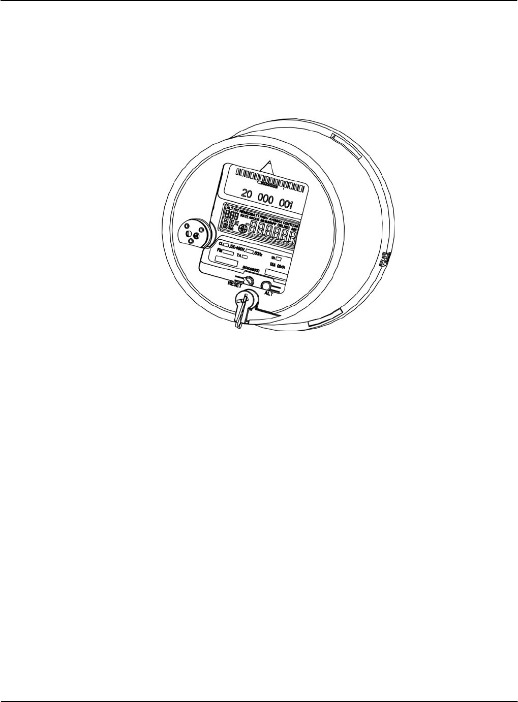
The iCon™ APX Advanced Functionality Meter is a commercial-grade, electricity meter. By
analyzing information from the metering industry, Sensus Metering Systems has developed a
new, configurable meter designed to meet the demands of commercial metering.
Figure 1-1: iCon APX Advanced Functionality Meter
Overview
This manual provides technical and support information for the iCon APX meter:
• Socket: Form 9S (8S) 20 Amp
• Socket: Form 16S (14S, 15S, 17S) 200 Amp
Manual Conventions Introduction
1-2 Introduction TM-iX0A-0805
Purpose
The purpose of this manual is to provide:
• Physical descriptions of the APX meters.
• Descriptions of fixed and optional features.
• A reference for meter set up, operation, troubleshooting, and maintenance.
This document is intended for technically qualified personnel of energy supply companies and
their contractors who are responsible for the system planning, installation, commissioning,
operation, maintenance, decommissioning, and/or disposal of meters.
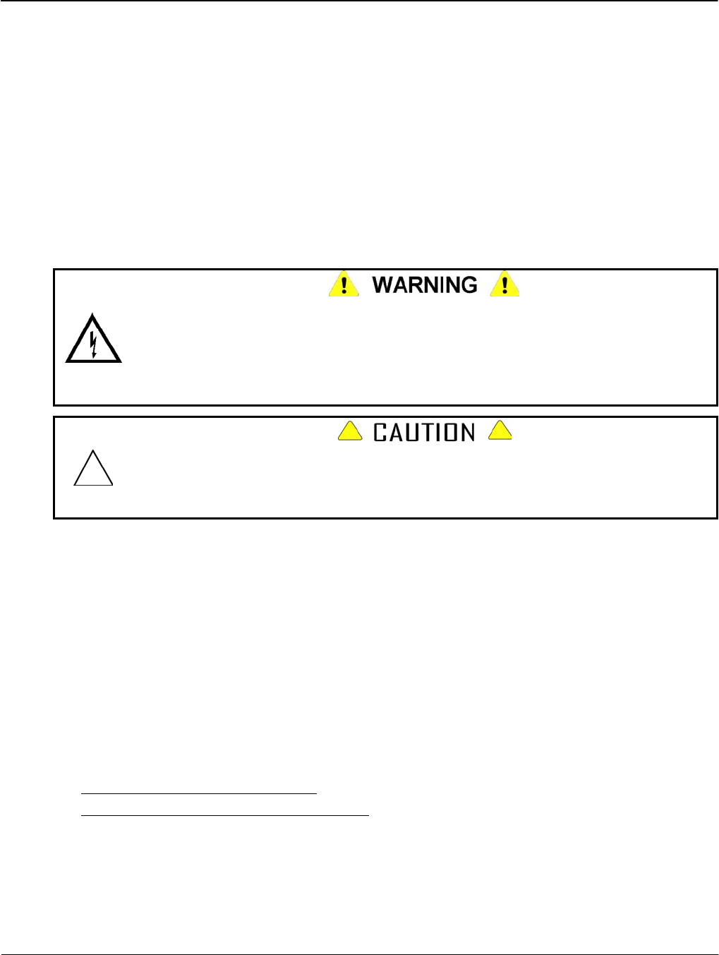
Safety
Hazardous voltages are present while power is applied to meters, meter sockets, or other
metering equipment. Any work on the energized equipment presents the danger of electrical
shock and can result in death or serious injury. The information contained within this
manual is intended to be an aid to qualified metering personnel. It is not intended to replace
the extensive training necessary to handle metering equipment in a safe manner.
Use extreme care when servicing the meter while power is applied.
Qualified electricians and metering specialists, in accordance with local utility safety
practices and utility requirements, should perform all work on this product with extreme
care. Failure to comply with this caution can result in the destruction of or damage to the
equipment and/or permanent loss of stored data..
All industry safety precautions must be observed during all phases of operation, service, and
servicing of the meters. Failure to comply with these precautions or with specific warnings in
this manual violates safety standards of design, manufacture, and the intended use of the
metering instrument. Sensus Metering Systems assumes no liability for the customer’s failure to
comply with these requirements.
Manual Conventions
This section provides additional information that may be required for meter configuration and
maintenance purposes.
Additional Information Sources
• Handbook for Electricity Metering, 10th Edition, Edison Electrical Institute
• Requirements for Watthour Meter Sockets, ANSI C12.7-1993

Introduction Manual Conventions
Notational Conventions
Hexadecimal Values
Hexadecimal values in this manual are expressed as follows:
• Values that are in hexadecimal notation are shown as two or four (4) characters followed by
the letter "h.” Each character can have a value from 0 through F. For example, 9C3Fh
• All other numbers are in decimal notation.
Ranges
Ranges, or parameters, expressed in this manual are expressed a pair of values separated by
ellipses. For example, 0…5 include numbers 0 and 5 and all of the values in between.
Register Notation and Usage
Registers are a part of the meter memory that contains the addresses that are used to hold specific
kinds of information. The following registers are contained in the APX meter. The information
stored in these registers is usually configured using the iConFig application software.
Billing Registers
The APX meter contains two Billing Registers. The Billing Registers store:
• Selected consumption readings
• The associated Maximum Demand readings
• The associated Cumulative Demand or Continuously Cumulative Demand.
Previous Demand Registers
The Previous Demand registers contain a snapshot of the Billing Registers captured during the
last Demand Reset. Any data in these registers is overwritten during the reset.
Status Register
The status register store meter dependent information (e.g., Low Battery, Meter errors, Demand
overloads)
History Log Register
The History Log registers store data for selected events that may occur during meter operation.
More than 40 different events can be recognized and the results stored in these registers.
Version 1.0 Introduction 1-3
Manual Conventions Introduction
1-4 Introduction TM-iX0A-0805
Applicable Standards
The iCon APX meter meets or exceeds the ANSI standards for commercial and industrial
electricity metering.
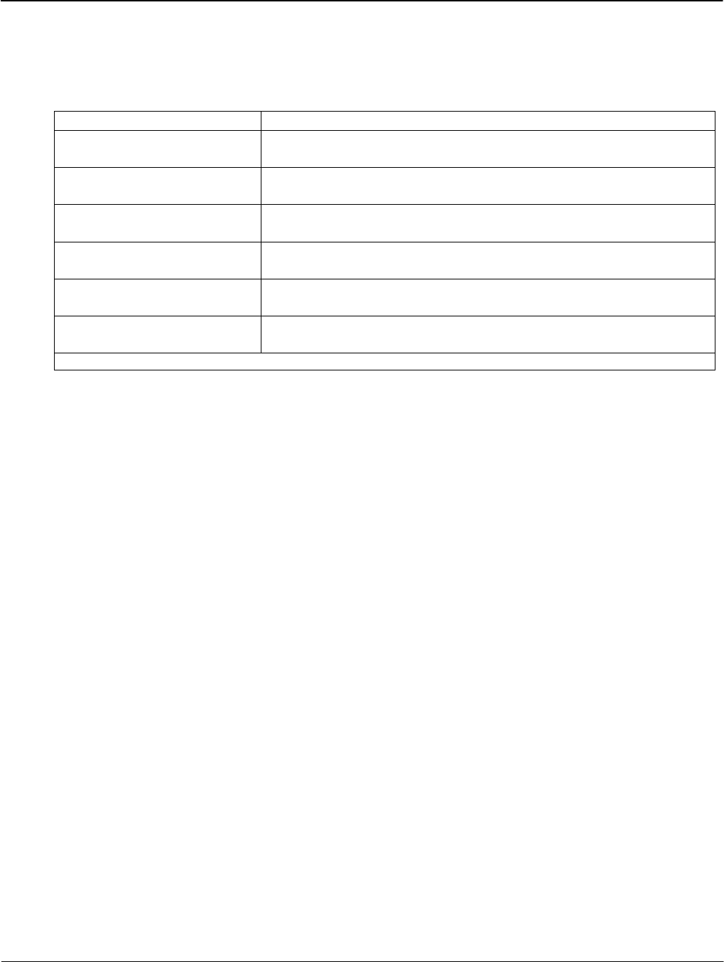
Table 1-1: Applicable Standards
ANSI C12.1 – 2001 American National Standard Code for Electricity Metering
ANSI C12.13-1991 American National Standard Code for Electronic Time-of-Use
Registers for Electricity Meters
ANSI C12.18-1996 American National Standard Code for Protocol Specification for
ANSI Type 2 Optical Port
*ANSI C12.19 - 1997 American National Standard Code for Utility Industry End Device
Data Tables
*ANSI C12.20 – 2002 American National Standard Code for Electricity Meters
0.2 and 0.5 Accuracy Classes
ANSI C12.21-1999 American National Standard Code for Protocol Specification for
Telephone Modem Communication
ANSI/IEEE C37.90 –1989 IEEE Standard Surge Withstand Capability (SWC) for Protective
Relays and Relay Systems
* - The iCon™ APX conforms to the standards, however the meters are not governed by them.

Meter Overview
iCon APX Meter
Version 1.0 Meter Overview 2-1
Chapter 2
iCon APX Meter
The iCon™ APX Advanced Functionality Meter continues to use same field-proven Sentec®
sensor technology found in the other meters in the iCon family.
Accuracy
The APX meter is built with a backbone of precision that exceeds ANSI C12.20 standards for
accuracy.
Reliability
The iCon APX meter uses a simple, unique modular design that meets the most stringent
performance requirements for revenue billing applications. This construction reduces the number
of connections thereby reducing the possibility of false data or metering related problems.
Expandability
Like the iCon meter, the APX meter employs an open architecture design that allows for easy
and cost effective AMR integration. The APX meter was designed with this idea in mind.
Tamper Resistance
Since there are no moving parts, the APX meter is not vulnerable to the tampering methods (e.g.,
using magnets, inserting foreign objects into the gears, inverting the meter in the socket) used to
affect electromechanical meters.
System Architecture Meter Overview
2-2 Meter Overview TM-iX0A-0805
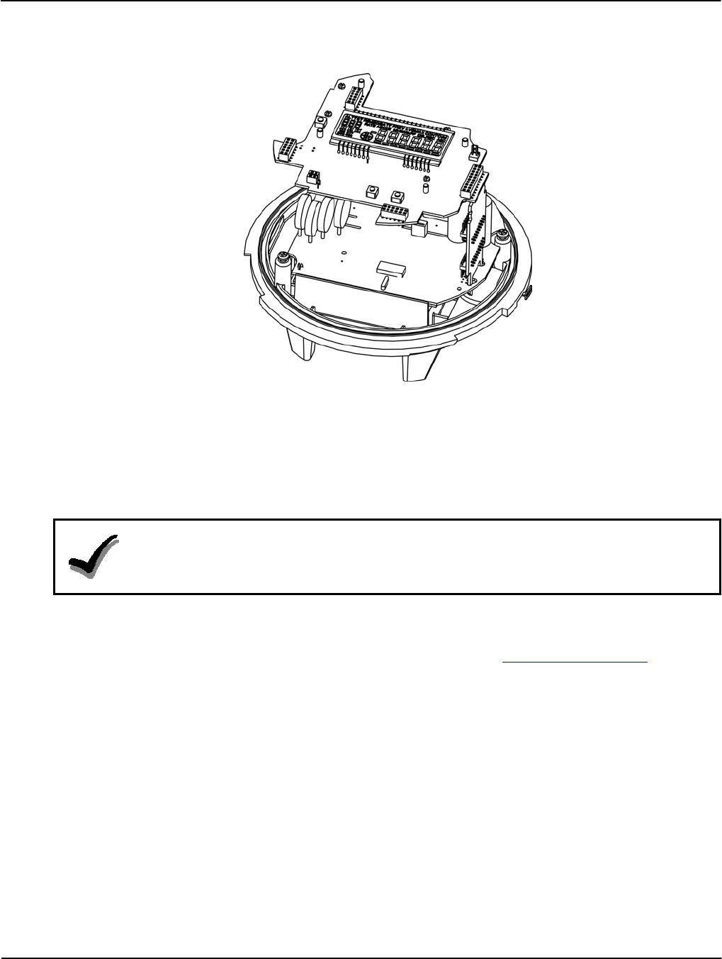
System Architecture
Figure 2-1 shows the APX meter with the Meter Cover and Register Cover removed.
Figure 2-1: APX Meter Internal Components
APX meters:
• Display accumulated electricity usage data on an easy-to-read liquid crystal display (LCD).
• Are compatible with industry requirements for mounting and device profile features.
• Are compliant with all applicable ANSI standards.
NOTE:
This manual describes some of the features available in iCon APX meters. At the time of
order, specific options are selected for each utility. Not all features may appear in all
meters.
APX meters meet or surpass the needs for automated billing measurement, data collection,
selected control and notification, and usage management for utilities, service providers, and
end-users (business-owners). For more information, please email askicon@sensus.com.
Meter Overview System Architecture
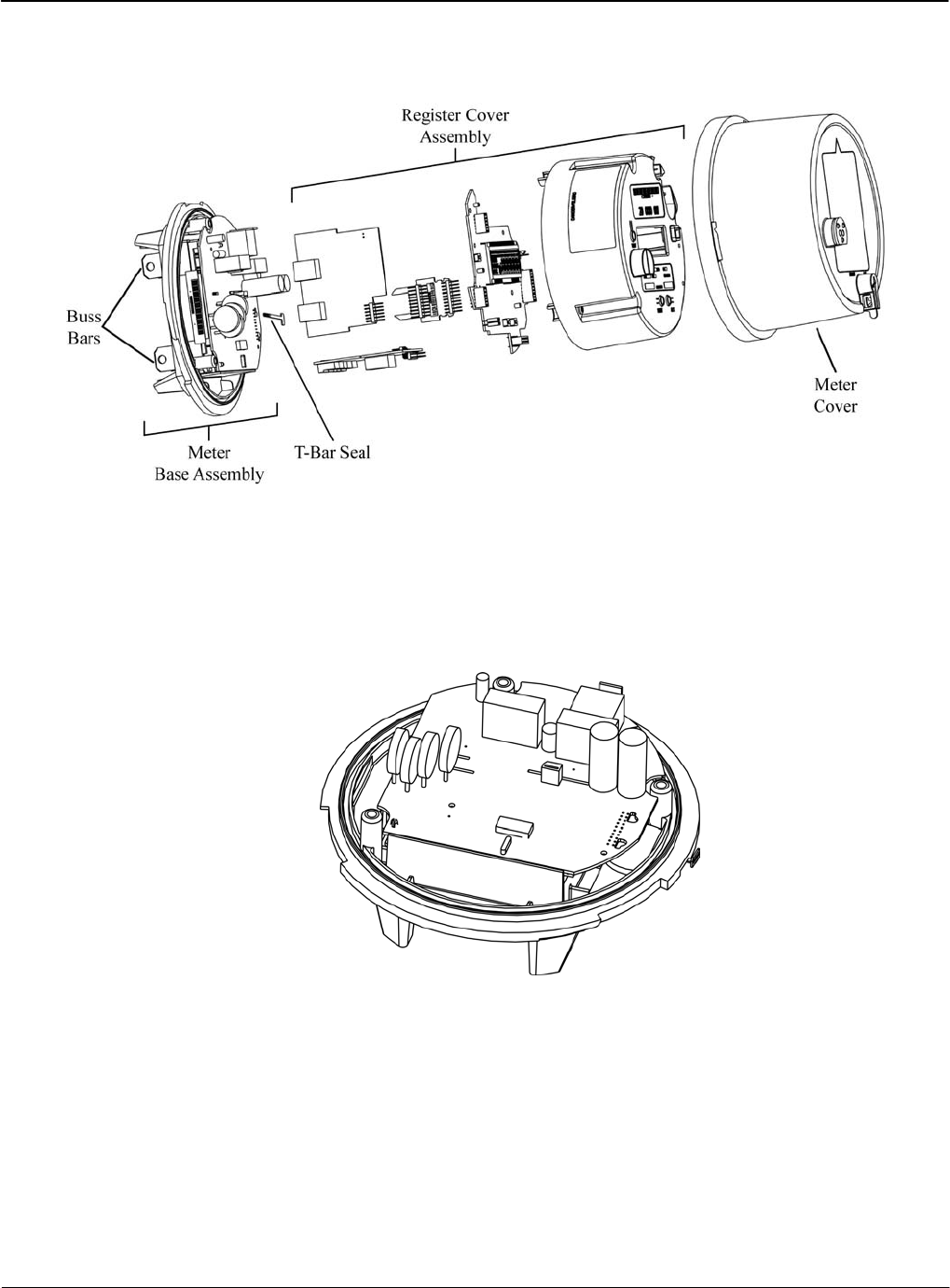
Hardware
The basic components of the meter are shown in Figure 2-2.
Figure 2-2: iCon APX Meter Components
Meter Base Assembly
The Meter Base Assembly consists of the Meter Base, the Sensor Board, and related hardware.
Figure 2-4 shows the Sensor Board in the Meter Base.
There are no field-serviceable parts in the Meter Base Assembly.
Figure 2-3: Meter Base Assembly
Meter Base
The Meter Base is molded from highly durable thermoplastics. It provides a stable platform for
the Sensor Board. In addition to the components described in this section, it contains the hangar
for mounting the meter, and the T-Bar for meter security.
Version 1.0 Meter Overview 2-3
System Architecture Meter Overview
2-4 Meter Overview TM-iX0A-0805
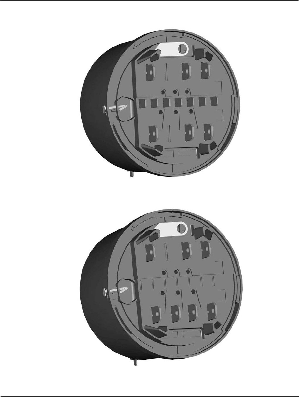
Figure 2-4 through Figure 2-6 provide views of the available APX meter Forms.
Figure 2-4 shows a transformer rated Form 9S (8S) Meter Base.
Figure 2-4: Form 9S (8S) Meter Base
Figure 2-4 shows a Form 16S (14S, 15S, 17S) Meter Base.
Figure 2-5: Form 16S (14S, 15S, 17S) Meter Base
Meter Overview System Architecture
For self-contained meters, there is an optional Phantom Load version of the Meter Base.
Figure 2-6 shows a Form 15S/16S Meter Base with the Phantom Load (closed position).
Figure 2-6: Form 15S/16S Meter Base - Optional Phantom Load
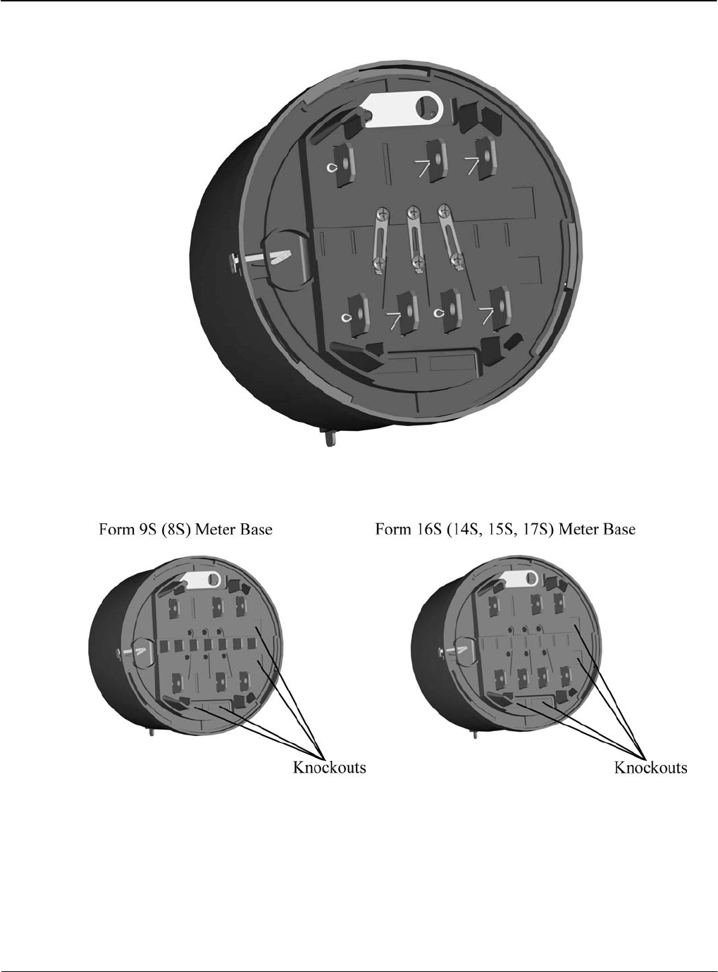
All meter bases provide knockouts for the option boards.
Figure 2-7: Meter Base – Option Board Knockouts
Version 1.0 Meter Overview 2-5

System Architecture Meter Overview
2-6 Meter Overview TM-iX0A-0805
Sensor Board
The Sensor Board is a part of the Meter Base Assembly and consists of the sensing circuitry,
buss bars, power supply, and connector ports. There are no field serviceable components in the
base assembly.
The module:
• Senses all of the voltages and currents for all phases passing through the meter
• Provides the DC power for the rest of the meter
• Contains the data of all of the sampled energy and voltages
• Supports reading of the sampled data by the Register Display Board
• Holds the calibration information stored in EEPROM
Buss Bars — The buss bars are conducting blades that carry the load current from the service
socket to the load. In self-contained meters, the buss bars provide the voltage inputs to the
metrology and provide power to the meter’s internal power supply.
Sensing Circuitry — The primary components include a patented linear current sensor and
integrated circuitry specifically designed for poly-phase electricity metering. The ADE7758 is a
24-pin, poly-phase, energy measuring, integrated-circuit chip with a serial interface and pulse
outputs. This chip measures/calculates the following values:
• Active Energy - Wh
• Reactive and Apparent Energy – VARh and VAh
• RMS Voltages
• RMS Currents
• Temperature
The chip is suitable for three-phase, three-wire and/or three-phase, four-wire Delta or Wye
services. This chip stores the measurement samples of each quantity and supports read operations
by the Register Display Board.
Switching Power Supply — The power supply is a true, three-phase, surge protected,
auto-ranging (96 VAC to 576 VAC) power supply. It accepts voltages present at the service
socket and provides DC power for the rest of the meter. The power supply functions even with
power present on only one phase.
Connector Ports — The Connector Ports provide the physical links to the Sensor Board for the
Interconnect Board and the Option Cards.
Meter Overview System Architecture
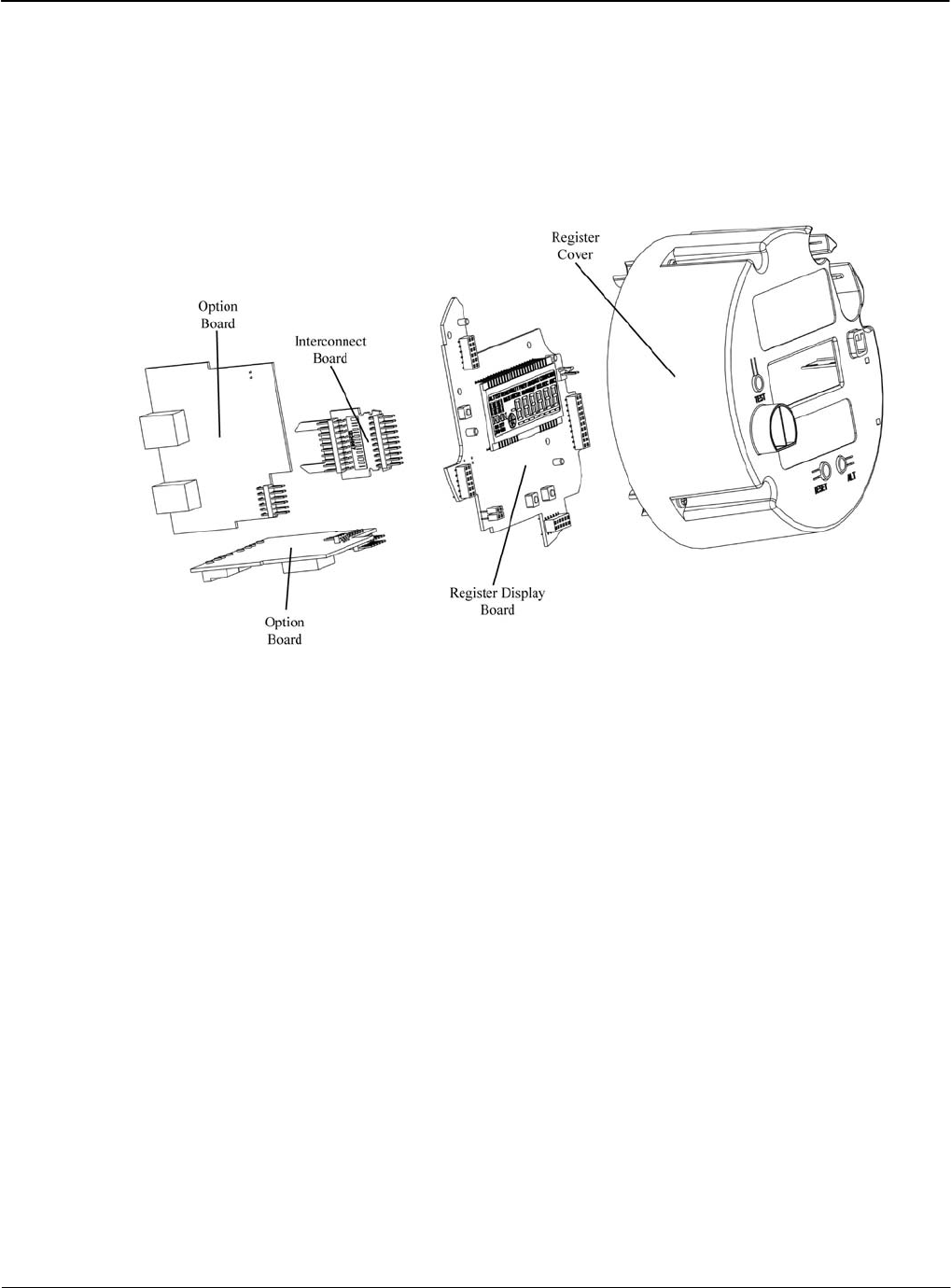
Register Cover Assembly
The Register Cover Assembly consists of:
• Register Cover
• Register Display Board
• Interconnect Board
• Option Boards
Figure 2-8: Register Cover Assembly – Exploded View
Version 1.0 Meter Overview 2-7
System Architecture Meter Overview
2-8 Meter Overview TM-iX0A-0805
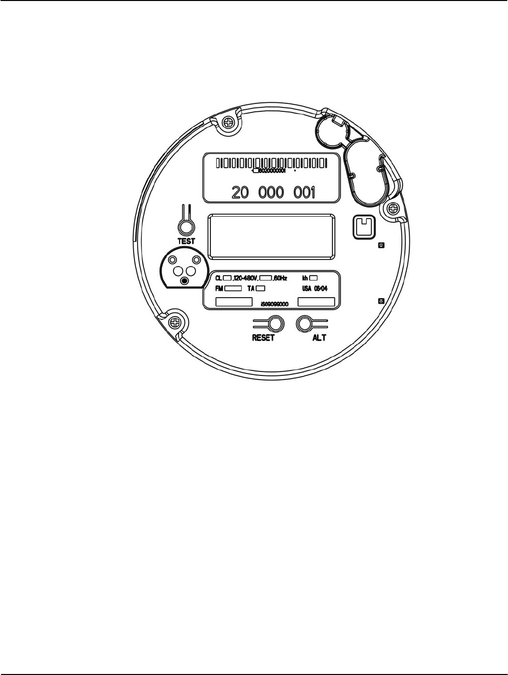
Register Cover
The Register Cover is an opaque shield that protects the meter’s internal components from
external tampering and serves as the mounting surface for the labels. The cover also contains
‘pockets’ to house batteries that maintain the DC voltage for circuitry required to function during
an outage; such as the RTC. Except for the Optical Port Shield, LCD, TEST tab, RESET tab, and
ALT tab, no internal components can be viewed through the Register Cover.
Figure 2-9: Register Cover
Labels
The meter has labels on the Register Cover. The Nameplate, and Warning Label are on all
Register Covers. If an AMR module is installed, an FCC Label will be present.
Upper and Lower Nameplate Labels
The upper and lower labels are compliant with the ANSI C12.10 – 1997 standard and may
include:
• Meter:
▪ Style Number
▪ Current class
▪ Form
▪ Service type
▪ Kh value
▪ Test Amps
▪ Accuracy Class

Meter Overview System Architecture
• Operating:
▪ Voltages
▪ Frequencies
• A unique meter identifier
• Descriptive information
Meter information required by the utility
• Factory-generated bar code for the:
▪ Meter ID
▪ Test board
Warning Label
The Warning Label contains a multi-lingual message on the hazards and potential consequences
of working on energized equipment.
FCC Label
The FCC Label is affixed to the Register Cover and may:
• Contain patent and part numbers
• Provide relevant FCC Part 15 compliance information
• Describe the operating conditions
• Provide additional compliance information pertaining to an optional RF AMR module
installed in the meter
The following Note applies to iCon APX meters containing the Sensus MXU Model 530-T RF
AMR module.
This device complies with Part 15 of the FCC Rules. Operation is subject to the following two
conditions: (1) This device may not cause harmful interference, and (2) this device must accept
any interference received, including interference that may cause undesired operation.
This device contains FCC ID: KCHMXU530T / IC: 2220A-MXU530T.
CAUTION: Changes or modifications not expressly approved by Sensus Metering Systems
could void the user's authority to operate the equipment.
Version 1.0 Meter Overview 2-9
System Architecture Meter Overview
2-10 Meter Overview TM-iX0A-0805
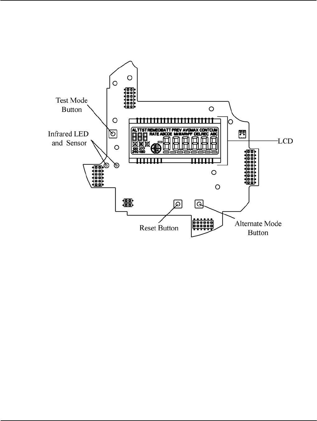
Register Display Board
The Register Display Board (display board) consists of a Liquid Crystal Display (LCD),
Alternate Mode button, Demand Reset button, Test Mode button, three option-board
connections, and an optical port consisting of one (1) infrared LED and one (1) infrared
LED sensor.
Figure 2-10: Register Display Board
The display board
• Includes connectors for plugging in the option boards and Interconnect Board
• Periodically reads data contained within the ADE7758 chip on the Sensor Board
• Parses the data into the different billing quantities
• Communicates the results of calculations by way of the LCD and/or remote communication
ports
• Manages the remote communication ports:
▪ ANSI C12-18, Type 2 compliant Optical Port
▪ RS-232 or RS-485
▪ Ethernet/Modem connection
▪ Third-party communication boards
• Stores the following data in non-volatile, flash memory:
▪ Meter firmware
▪ Meter status
▪ History Log
▪ The configuration program created with iConFig™
▪ Billing information
Meter Overview System Architecture
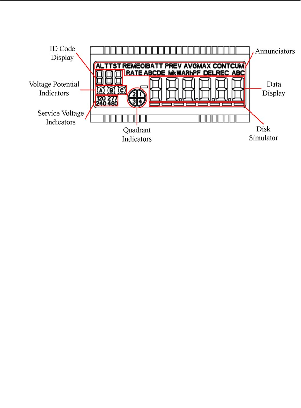
Liquid Crystal Display
The LCD provides meter reading and test information. The information on the LCD is visible in
direct sunlight and can be read at angles of 15 degrees above and below the LCD centerline.
Figure 2-11 shows the LCD’s Annunciators and Displays.
Figure 2-11: LCD Annunciators, Displays, and Indicators
Annunciators
Annunciators are composed of LCD segments that can be enabled/disabled to display the
following meter conditions and measurements.
ALT (Alternate List) — This Annunciator illuminates when the meter shows the values from the
Alternate Display List. No measurements are affected while in this display mode.
TST (Test List) — This Annunciator illuminates when the meter is in Test Mode.
REM (Remote Communications) — This Annunciator illuminates when the meter detects
outside connections to the meter on any of its communication ports.
EOI (End of Interval) — This Annunciator illuminates at the end of every Demand Interval. The
Annunciator remains illuminated for four (4) seconds and then extinguishes.
BATT (Battery) — When the meter contains a Real-Time-Clock (RTC) battery, this
Annunciator illuminates when the meter detects the installed battery’s useful life is at or below
15 percent.
PREV (Previous) — When configured and the meter contains previously stored billing data, this
Annunciator illuminates when the Data Display is showing previous billing data.
AVG (Average) — When configured, this Annunciator illuminates when the LCD is showing
the average system voltage or current.
MAX (Maximum), CONT (Continuously), CUM (Cumulative) — These Annunciators
illuminate when the LCD shows Peak Demand quantities. When configured, the MAX (Peak
Demand), the MAX and CUM (Cumulative Peak Demand), or MAX, CONT, and CUM
(Continuously Cumulative Peak Demand) Annunciators illuminate.
RATE A, B, C, D, E — When configured for Time-of-Use (TOU), the RATE Annunciator and
one of the alphabetic Annunciators illuminate when the Data Display shows the applicable rate
information. The displayed information is configured from the Switch Times tab of the
TOU / Calendar module of iConFig.
Version 1.0 Meter Overview 2-11

System Architecture Meter Overview
2-12 Meter Overview TM-iX0A-0805
M (Mega) — This Annunciator illuminates when the value shown by the Data Display is one
million of a specified unit.
k (kilo) — This Annunciator illuminates when the value shown by the Data Display is one
thousand of a specified unit.
V (Volts), W (Watts) — The W consists of two V-shaped Annunciators. When one Annunciator
is illuminated, it appears as the letter V. When both Annunciators are illuminated, they appear as
the letter W. These Annunciators illuminate when the value shown by the Data Display is either
Volts or Watts.
A (Amperes), R (Reactive) — These Annunciators can be used in conjunction with the
V Annunciators. They illuminate when the value shown by the Data Display is as follows:
• VA = Voltamperes
• VAR - The product of the total Voltamperes and the sine of the angle between current and
voltage.
h (Energy) — This Annunciators illuminates when the Data Display is showing an integrated
quantity.
PF (Power Factor) — This Annunciator illuminates when the value in the Data Display shows a
power factor value. Power factor values are calculated based upon the integrated quantities the
meter is configured (either factory default or with the iConFig application) to accumulate.
DEL (Delivered), REC (Received) — These Annunciators illuminate when the value in the Data
Display shows the contents of the related Delivered or Received billing registers. These
Annunciators do not indicate whether the actual power flowing through the meter is delivered or
received.
A, B, C (Per Phase Quantity) — These Annunciators illuminate when the value in the Data
Display is for the detected phase. When all Annunciators are extinguished, the quantity is for all
three phases.
Displays and Indicators
ID Code Display — When configured, this three-digit identifying code is displayed
simultaneously with an item shown in the Data Display area. (typically, a unique code is
configured for each Data Display item).
120, 277, 240, 480 (Service Voltage Indicators) — The meter detects the nominal service voltage
during power up and illuminates the display of the detected voltage. If the nominal service
voltage cannot be determined (as a result of an incorrectly wired socket, for example), all Service
Voltage Indicators are illuminated.
Voltage Potential Indicators — Illuminate when voltage is present in those phases
Quadrant Indicators — Illuminate to show the direction of the power presently flowing
through the meter and whether the power factors are leading or lagging. The quadrants are
defined as follows:
• Quadrant 1 (lagging) – Wh and VARh delivered to the customer.
• Quadrant 2 (lagging) – Wh received from the customer and VARh delivered to the customer.
• Quadrant 3 (leading) – Wh and VARh received from the customer.
• Quadrant 4 (leading) – Wh delivered to the customer and VARh received from the customer.

Meter Overview System Architecture
Meters that do not have Reactive or Apparent energy measurements enabled will only be able to
indicate the direction of the kWh energy. These meters will illuminate Quadrant 1 and
Quadrant 4 to indicate energy flowing to a customer and Quadrant 2 and Quadrant 3 to indicate
energy received from a customer.
Data Display — The Data Display is composed of LCD segments that can display letters, digits,
and symbols. The values can be configured as follows:
• Energy, Demand and Power Factor Values:
▪ Display formats: kilo (103), Mega (106), or unity (100)
▪ Display values of up to five (5) digits
▪ Display up to three (3) decimal places
• Date Format
▪ MM-DD-YY
▪ DD-MM-YY
▪ YY-MM-DD
• Time can be displayed in either 12-hour or 24-hour formats as hh:mm:ss
• A minus (-) sign can be displayed for negative net values
Disk Simulator —The Disk Simulator is an eight-segment bar that is under the Data Display. In
normal operating conditions, the Disk Simulator appears to move from left to right (delivered
power) and increments once depending upon the Kh value. In reverse power conditions, it
appears to move from right to left.
Buttons
Alternate Mode
Activating this button manually changes the meter from its present mode to display and scroll
through the Alternate Display Register List that was configured through iConFig. Also, while in
Test Mode, this button allows you to scroll through the Test Mode Display List items.
Demand Reset
Activating this button causes the meter to:
• Store a copy of all billing register data to the Previous Demand register.
• Add the present Peak Demand values to their associated Cumulative Demand values.
• Resets the Peak Demand value to zero (0).
Test
Activating this button manually changes the meter from its present mode to Test Mode. Pressing
and holding this button for three seconds causes the meter to enter ‘Test Lock’. See
“Test Mode Lock” below.
Infrared LED and Sensor
The infrared LED, sensor, and supporting circuitry combine to make up the electronics of an
ANSI Type 2 optical port. The signal levels conform to the ANSI C12.18-1996 Protocol
Specification for ANSI Type 2 Optical Port.
Version 1.0 Meter Overview 2-13
System Architecture Meter Overview
2-14 Meter Overview TM-iX0A-0805
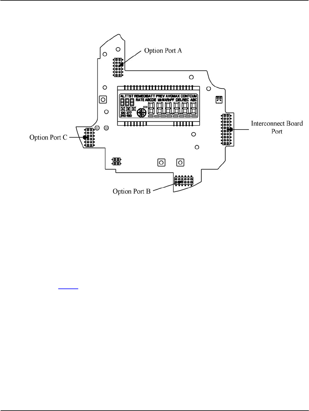
Connector Ports
The Register Display Board contains connector ports for option boards and the Interconnect
Board. Figure 2-12 shows the locations of the connector ports.
Figure 2-12: Register Display Board Connector Ports
Interconnect Board
The interconnect board provides a physical path for data and power supply signals from the
Sensor Board in the Meter Base Assembly to the Register Display Board.
Option Boards
To ensure client satisfaction, the APX meter is designed to support additional features and
upgrades through the incorporation of option boards which connect to Option Ports A, B, and C.
Visit to the Sensus website for more information on these boards as more become available.
Meter Cover
The Meter Cover:
• Provides:
▪ Protection from the weather and other contaminants
▪ A clear view of the LCD and Labels located under the cover
▪ An integrated ANSI Type 2 Optical port
▪ Access to the RESET and ALT switches by way of a sealable RESET/ALT Lever
• Limits unauthorized access to the internal switches, components, and buttons.

Meter Overview Metering Capabilities
Figure 2-13: Meter Cover
After final set-up and calibration of the meter at the factory, the Meter Cover and Meter Base
Assembly are sealed with a T-Bar. The RESET/ALT Lever can also be sealed using an
industry-standard Demand Reset Seal. Broken or missing seals provide evidence of possible
tampering.
Metering Capabilities
The APX meter is capable of a wide range of measurements and calculations based on the needs
of the customer. This section provides some descriptions of the configurable settings in the APX
meter.
The APX meter can be configured to provide the average value of power, or related quantity,
over a specified period of time (Demand metering). The LCD displays the results in the form of
kW, kVAR, or kVA.
Demand parameters are stored in the meter and control events such as:
• The length of the:
▪ Demand Interval
▪ Demand Subinterval
▪ Test Mode Demand Interval
▪ Test Mode Demand Subinterval
• Whether or not to use:
▪ Demand Forgiveness
▪ Outage Recognition time
▪ Demand Reset Lockout Period
Version 1.0 Meter Overview 2-15

Metering Capabilities Meter Overview
2-16 Meter Overview TM-iX0A-0805
Display Lists
The meter maintains up to four (4) display lists. The contents of each list and the order in which
items appear is configured using iConFig. Each list item is displayed as the meter scrolls through
the list depending upon the meter’s operating Mode.
Normal Display List
When the meter is in Normal Mode, the Normal Display List is displayed. This list usually
contains quantities and data used for customer billing and is the default list displayed when
power is restored (unless the Test Lock feature has been activated – see “Test Mode Lock”
below). This list is displayed after exiting any of the other modes.
In this mode, the meter automatically scrolls through the configured List Items at the
configured rate.
Alternate Display List
When the meter is in Alternate Mode, the Alternate Display List is displayed. This list usually
contains information that is not normally used for customer billing (e.g., site surveys, debugging
the meter, marketing information, future equipment planning). This list is displayed when the
meter is in Normal Mode and the ALT button is pressed or by way of remote commands from
iConFig.
In this mode, the meter automatically scrolls through the configured List Items at the configured
rate. The meter automatically exits Alternate Mode after the configured timeout expires. When
the timeout is set to zero (0), it will remain in Alternate Mode until the power is removed.
To exit Alternate Mode, press the ALT button again or by way of remote commands using
iConFig.
Test Display List
When the meter is in Test Mode, the Test Display List is displayed. This list usually contains the
quantities and data that can be used to verify meter calibration. This list is displayed when the
meter is in Normal Mode or Alternate Mode and the TEST button is pressed or using remote
commands from iConFig.
Upon entering Test Mode, the TST Annunciator on the LCD illuminates, and the meter:
• Suspends regular metering
• Stores all of the billing data into non-volatile memory
• Resets all of the Energy and Demand values to zero (0)
In Test Mode, the measured quantities are stored in the Test Mode registers and not in the
customer-billing registers. Use the RESET button to set all of the metering and demand
quantities in the Test Mode registers back to zero (0) and the ALT button to manually scroll
through the items in the Test Display List. The meter automatically exits Test Mode after the
configured timeout expires. When the timeout is set to zero (0), it will remain in Test Mode until
the power is removed.
To exit Test Mode, press the TEST button or use remote commands from iConFig. Upon
exiting Test Mode, the customer-billing data is restored.
Meter Overview Metering Capabilities
Test Mode Lock
This feature allows a utility to run special tests that require the meter to remain in Test Mode
even after temporary interruptions in power.
When the Test Mode Lock feature has been activated, the meter starts back up (i.e., after power
is restored after an outage) in Test Mode provided it is still within its configured timeout period.
To activate Test Mode Lock:
1. Ensure the meter is in Normal Mode. Depending on the mode, refer to the appropriate
display list paragraph above.
2. Press and hold the TEST button for three (3) seconds. The TST Annunciator will flash On
and Off to indicate that the Test Mode Lock feature is active.
3. To exit Test Mode while in Test Mode Lock, press the TEST button again.
NOTE:
If the Test Lock feature is activated and the timeout period is set to zero (0), the meter will
start up and remain in Test Mode indefinitely.
Diagnostic Display List
When the meter is in Diagnostic Mode, the Diagnostic display list will be presented. This list
usually contains per phase instantaneous measurements and information (such as volts, amperes,
watts, volt-amperes, volt-amperes reactive, etc.). This information may be useful in
troubleshooting wiring problems or verifying that the wiring is correct.
While in Diagnostic Mode, the meter continues to measure and store usage data in the billing
registers.
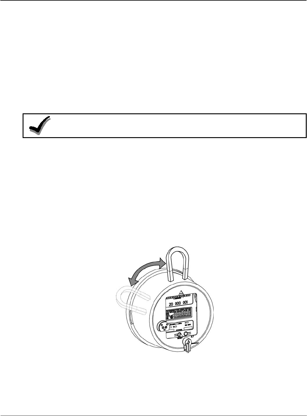
To enter Diagnostic Mode, pass a magnet over the side of the meter as shown in Figure 2-14..
Each subsequent swipe of the magnet will advance the display to the next item in the list. It is
possible to use the magnet in the Optical Probe.
Figure 2-14: Scrolling Through Display List
Version 1.0 Meter Overview 2-17

Metering Capabilities Meter Overview
2-18 Meter Overview TM-iX0A-0805
While in Diagnostic Mode, the meter continues to measure and store usage data in the billing
registers.
After the configurable timeout period has expired, the meter automatically reverts back to the
Normal Display List. To manually exit Diagnostic Mode, use the RESET/ALT Lever to press the
ALT button. Alternatively, this mode can be entered and exited by way of remote commands
using iConFig.
The meter automatically exits Diagnostic Mode after the configured timeout expires. When the
timeout is set to zero (0), the meter will remain in Diagnostic Mode until the power is removed.
Security
The meter is capable of storing up to eight separate passwords, each with its own set of access
permissions. Read, Write, and No Access permission settings can be applied to the following
categories for each password:
• Identification/Status
• Procedures
• Billing
• Security
• Schedule
• Load Profile
• History Events
• Thresholds/Alarms
• User Defined (ANSI C12.19 User Defined Tables)
• Option Boards
• Misc - Manufacturer Defined Tables

Operation
Hardware Setup
Version 1.0 Operation 3-1
Chapter 3
The iCon™ APX Advanced Functionality Meter is configured using the iConFig™ application.
This chapter provides brief descriptions of the Modules used to configure the meter.
Refer to iConFig Start-up and User’s Guide for instructions on configuring the meter.
Hardware Setup
The information in this section is not intended to provide instructions to unqualified personnel
nor replace the extensive training needed to safely handle the metering equipment. The set-up of
all meters shall be accomplished by qualified electricians and metering specialists.
The procedures described in this section are recommended for new or upgraded meters. After
setting up the meters, it may be necessary to program/reprogram and/or calibrate the meter.
The set-up of all meters shall be accomplished by qualified electricians and metering specialists.
All Meters
In order to insure security, the meters are protected by two seals.
• A T-Bar Seal that goes on the back of the meter
• Demand Reset Seal that secures the RESET/ALT Lever.
After set-up is complete, seal the meters.
Hardware Setup Operation
3-2 Operation TM-iX0A-0805
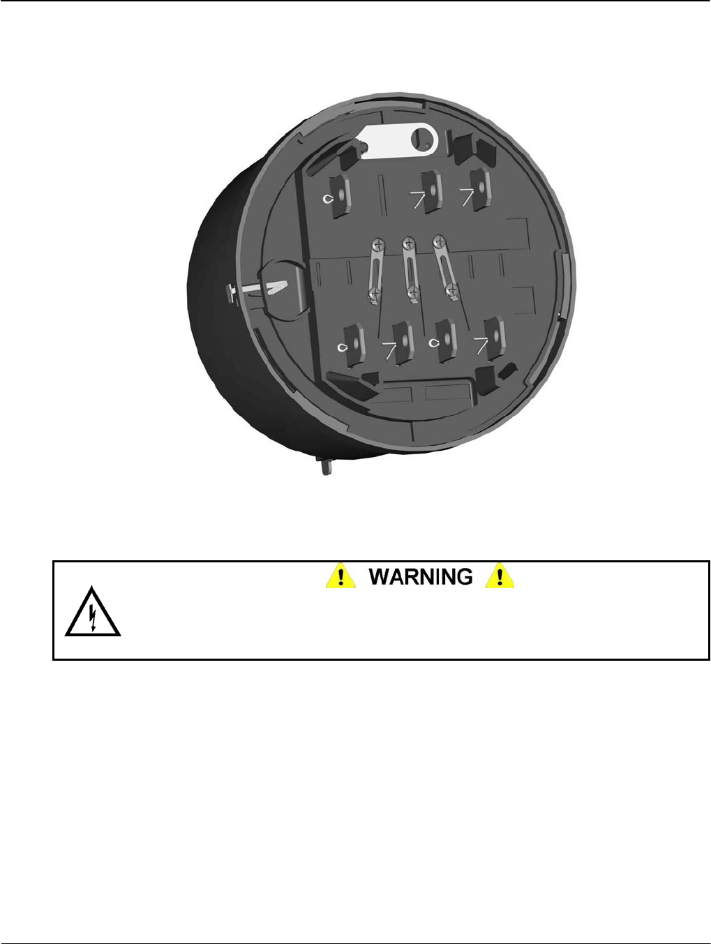
Self-Contained Meters
Some self-contained meters have Phantom Load links on the bottom of the Meter Base
Assembly. Ensure the links are all up and secured with the screws.
Figure 3-1: Phantom Load Links (closed)
Calibration Check
Do not permit unauthorized personnel to operate meter-testing equipment or to test meters.
Hazardous voltages can be present, exposing personnel to the risk of death or serious injury,
and exposing equipment to the risk of damage. Only authorized, trained personnel may
operate the meter-testing equipment, using approved test procedures and safety precautions.
Depending on the meter form and the particular requirements of the test board, you may have to
first ‘open’ the Phantom Load Links.
To perform a calibration check:
1. Loosen the two screws on each link.
2. Open the Phantom load links by:
a. Loosening all of the screws on each link
b. Sliding the links down until they stop
3. Re-tighten the lower screws enough to prevent any link from moving.
4. Install the meter into your test board.
5. In the controlling software for your test board, choose the appropriate meter form (Form 9
or Form 16).
6. Perform the calibration check.
Operation Hardware Setup
After completing the calibration check:
1. Remove the meter from the test board.
2. Close the Phantom Load links by:
a. Loosening the lower screws on each link
b. Sliding the links up until they stop
3. Securely tighten all of the screws to prevent the slides from moving.
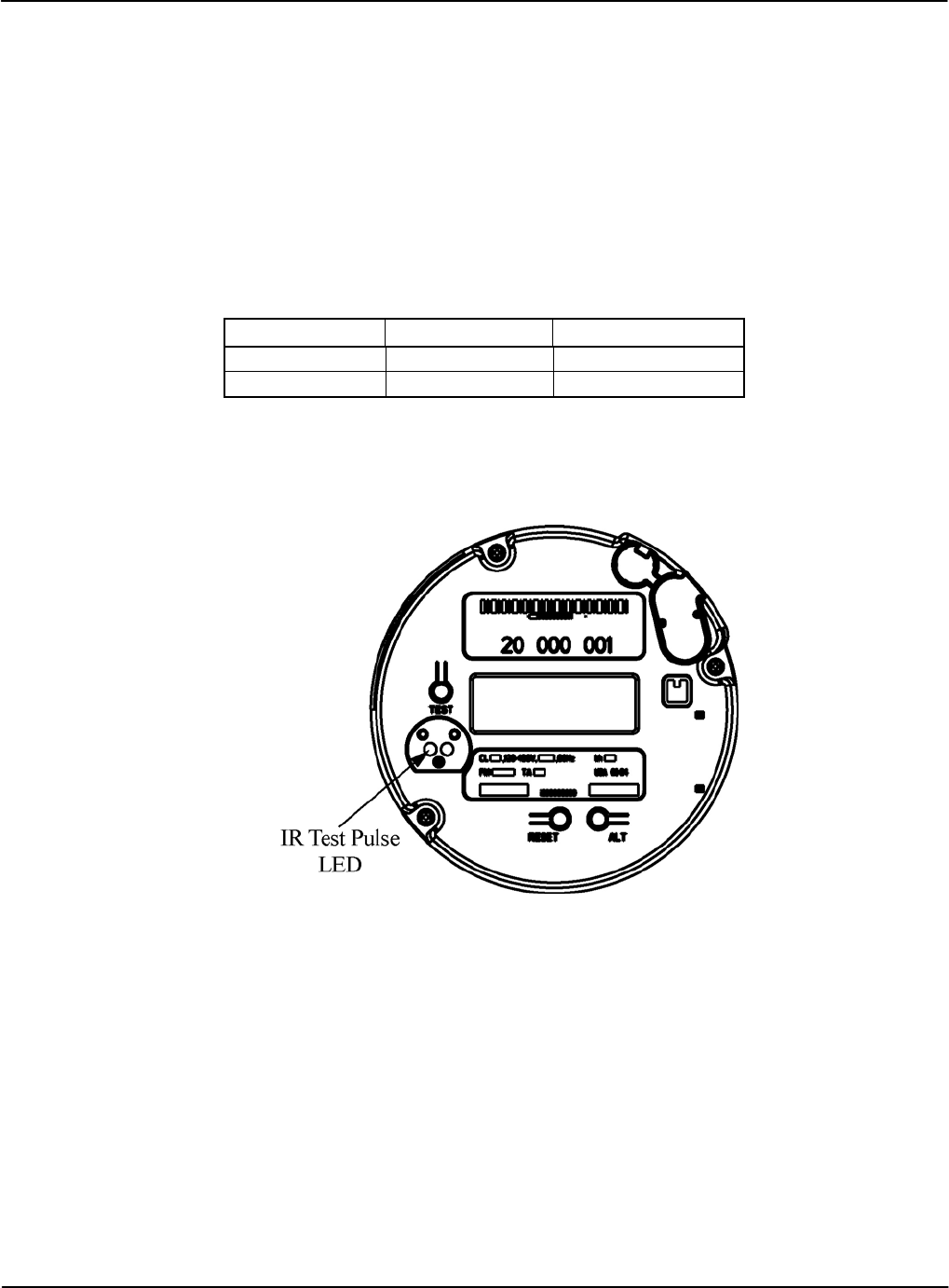
Testing
To interface with test equipment, the meter generates test pulses. The energy value assigned to
each test pulse is defined as the meter Kh and can be configured to value that is a multiple of 0.2.
Meter Default Kh Range (Wh/Pulse)
Form 9 1.8 Wh/pulse 0.2 to 40.8
Form 16 21.6 Wh/pulse 0.2 to 99.8
The test pulse output is compatible with all ANSI-rated laboratory and field test equipment and
is transmitted through the Infrared (IR) Test Pulse LED. When aligning the optical pick-up in
front of the IR Test Pulse LED. Position the pick-up so that it is perpendicular to the IR Test
Pulse LED. See Figure 3-2.
Figure 3-2: Location of the Infrared Test Pulse LED
Version 1.0 Operation 3-3

Hardware Setup Operation
3-4 Operation TM-iX0A-0805
IR Test Pulse LED Background
The iCon APX meter contains a Metering Chip that is used for the measurement of energy
(voltage * current). The test pulse signal is based on an output from this chip. This signal is
routed up through the display board to the Infrared (IR) LED in the optical port on the face of the
meter. The meter controls the function of the IR LED. When the meter detects communication
activity on the sensor portion of the optical port, it stops the IR LED from sending test pulses and
switches it for use as a transmitter. Once communication has ended, the meter reverts the
IR LED back to a test-pulse output.
To allow the meter to properly detect the service and restore all its billing and status registers, a
start-up delay of seven (7) seconds is required at the beginning of each meter test operation.
Setting the Start-up Delay
Below are instructions on how to set the start-up delay on the following test boards:
• WECO
• UTEC/RFL
If you are using a test board not identified above, please contact Sensus Metering Systems to
have it added to this document for other’s benefit.
WECO – Windows software
1. Execute the Winboard software.
2. Close the Winboard – Meter Testing window if open.
3. Enter the Winboard-Administration window.
4. Select the Administration menu.
5. Select Workstation Settings.
6. Select the Station 1 tab.
7. Set the Standard Settling Time to 7 seconds (with other settling times, this will result in a
delay time of approximately 10 seconds overall).
8. Select Save then Close.
9. If you have problems changing this in the WECO software, call 601-933-0900.
WECO – DOS software
1. Execute the DOS software.
2. Press the F8 function key for the Setup menu.
3. Set the KWH Test Dwell Time field to 7 seconds (with other settling times, this will result
in a delay time of approximately 10 seconds overall).
4. Press the F1 function key to save and return.
5. If you have problems changing this in the WECO software, call 601-933-0900.

Operation Hardware Setup
UTEC/RFL – Windows software
1. Enter Syslink DB Maintenance.
2. Enter Meter Test under Testset Group.
3. Select Testset.
4. Edit SubTest.
5. Enter Testpoint screen.
6. Select Testpoint to edit.
7. Change Stabilization Delay to 10 seconds.
8. Save changes.
9. If you have problems changing this in the UTEC software, call 800-952-8832.
UTEC/RFL – DOS software
The UTEC/RFL DOS software does not have a provision for a delay time. The test starts with
the first test pulse the test board receives after voltage and current are applied to the meter. As a
result, spurious results may occur when using this test board to test the iCon 12S meter.
Display Board Check
After applying power to the meter, ensure the LCD is active and displaying meter information
based upon the configured display modes.
Test Mode
The purpose of Test Mode is to allow you to verification the calibration of the meter without
losing any customer billing data. Also, the Demand Interval for Test Mode can be shorter than
for other modes allowing you to check the Demand measurement within the meter much faster.
Refer to the iConFig Start-up and User’s Guide for information on configuring Display Modules
and Demand Modules.
To put the meter in Test Mode using the TEST button:
1. Remove the Meter Cover. Refer to “Removing the Meter Cover” in Chapter 4.
2. Press the
TEST button.
It is also possible to put the meter into Test Mode using iConFig.
Upon entering Test Mode:
• A “snapshot” of all of the customer-billing data is taken and stored in separate locations. Test
billing data and test data are not applied to the customer’s billing data while the meter is in
Test Mode.
• The TST Annunciator illuminates.
• The first item in the Test Mode Display List is shown on the LCD.
To scroll through the items in the Display List, press and release the ALT button. When you
reach the last item and press the ALT button, the meter will recycle to first item in the Display
List.
Version 1.0 Operation 3-5

Installation Operation
3-6 Operation TM-iX0A-0805
Test Mode Operation
While the meter is in Display Mode, the Test Pulse correlates to the energy value that is visible
on the LCD.
NOTE:
If the Display List item does not have an energy reading, the Test Pulse will correlate to
the kWh present at the meter.
Example:
If the item on the Display List is kWh delivered, the Test Pulse will correspond to the
kWh presently going through the meter.
When you press and release the ALT button and the next item on the Display List is
kVAR hours, the Test Pulse will correspond to the kVAR hours.
The Test Pulse constant (Kt) in Test Mode can be different than the constant (Kh) that is used in
Normal, Alternate, and Site Diagnostic Modes.
Test Lock
To put the meter into Test Lock from Normal Mode, press and hold the TEST button
[approximately three (3) seconds] until the TST Annunciator flashes. While in Test Lock, the
TST Annunciator will flash.
In Test Lock the meter remains in Test Mode for the amount of time configured in the Test Mode
Timeout period, even if power is cycled during that time. If the Test Mode Timeout period is set
to zero (0), the meter will remain in Test Lock indefinitely. Regardless of whether the meter is in
Test Mode or Test Lock, pressing the Test button a second time causes the meter to revert back
to Normal Mode.
When exiting Test Mode, all previously stored customer-billing data from the “snapshot” is
restored to the billing registers and the meter returns to Normal Mode.
Reset Button
It is possible to reset the energy and Demand values in the Test Mode registers without having to
cycle the meter through different modes. While in Test Mode, press and release the RESET
button to reset the Test Mode registers.
Installation
The APX meter is designed to be compatible with the mechanical form factor of existing
electromechanical, commercial meters. This design allows technicians and trained meter
personnel to perform meter installations easily and without the use of specialized tools.
To install the meter, follow the procedures established by your company for standard commercial
meters.
Should the meter be configured to monitor for diagnostic errors, it may be necessary for the
technician to observe the meter for several minutes to ensure no error messages appear. Refer to
“
Operation Installation
Diagnostics and Alarms” below.
Meter Power-Up
NOTE:
If the meter was in Test Lock or the Test Mode timeout period had not
expired, the LCD will display the last item that was shown on the LCD at the
time power was removed.
After installing the meter into a socket and applying power, the meter should boot up and start
cycling through the Normal Display List unless:
• The meter was powered down while in Test Lock
• The Test Mode Timeout Period has not expired.
In addition to the boot-up items discussed in this section, additional settings can be configured
using iConFig.
NOTE:
If the meter was in service prior to powering down, meter and billing data is
automatically stored. During power-up, the meter retrieves the stored data.
After power is applied to the meter, the meter:
• Determines the service type
▪ Wye
▪ Delta
• Determines the phase rotation
▪ A, B, C
▪ C, B, A
• Detects any missing voltages
• Verifies the service voltages
▪ Phase-to-Neutral
o 120
o 240
o 277
▪ Phase-to-Phase
o 208
o 480
NOTE:
If the meter detects phase angle errors, the meter runs industry-standard diagnostics (see
“Diagnostics and Alarms” below)
• Verifies the phase angles are correct for the service type (variances can be configured
with iConFig).
Version 1.0 Operation 3-7
Configuring APX Meters Operation
3-8 Operation TM-iX0A-0805
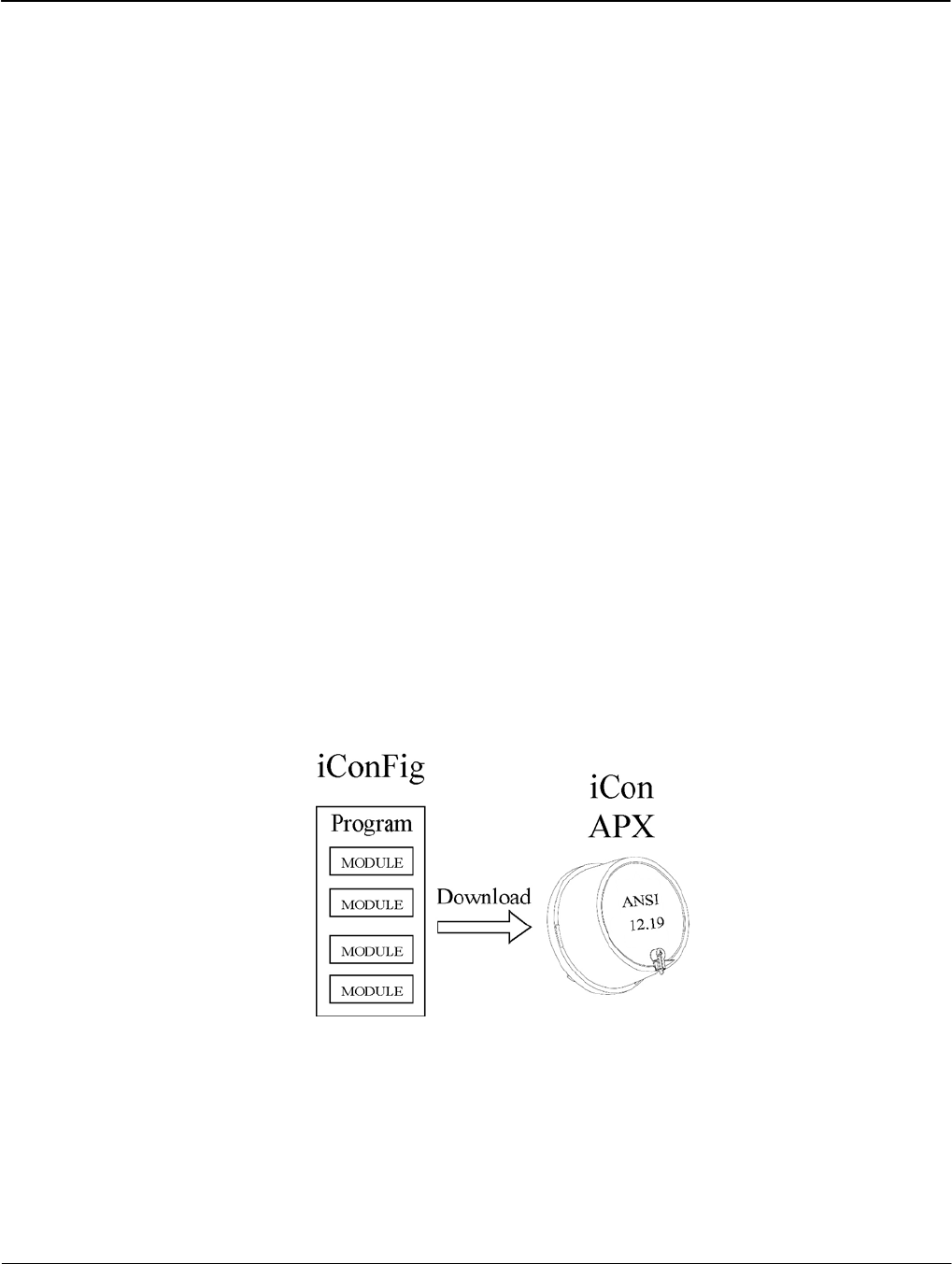
Configuring APX Meters
With iConFig, users can create or edit configuration programs that can be downloaded into APX
meters. iConFig is a user-friendly software package that has been developed to configure,
troubleshoot, and read the APX meter. iConFig is designed to be a flexible,
Microsoft® Windows-based application that runs on:
Windows:
• 98SE
• NT 4.0
• 2000 (any version)
• Millennium Edition (Me)
• XP (any version)
iConFig is used to perform the following functions:
• Configure the meter using “Programs”
• Read the meter
• Generate reports
• Upgrade/Downgrade meter capabilities
• Update the firmware
The meter may be preprogrammed at the factory for basic commercial metering. Although
certain parameters are customizable when ordering the meters, additional configurations are
accomplished through iConFig. Refer to the online tutorials and the iConFig Start-up and User’s
Guide
iConFig configures the meter by converting the desired settings into hexadecimal code and then
downloads those settings to the tables within the meter (in accordance with ANSI 12.19).
Figure 3-3: iConFig Application

Operation Configuring APX Meters
Identification
The Identification data contains information about the utility, the configuration program, vendor,
and other meter data. The data in this Module is for informational purposes and has no effect on
the operation of the meter.
The following identification data are permanently stored in meter memory. The data is stored at
the factory and no changes are allowed.
• Manufacturer’s serial number
• Firmware version
• Nameplate information
The APX meter can store additional, customer required identification data:
• Utility meter ID
• Account number
• Miscellaneous ID
• Program vendor
• Program
▪ Version number
▪ Revision number
• Owner
• Utility division
• Service point
• Customer ID
• X, Y, and Z coordinates
• Tariff ID
All of these data are for informational/identification purposes only and have no effect on the
operation of the meter. The meter provides the utilities a place to store additional information
that is important to their billing or tracking system.
Metering Constants
The APX meter allows the following Metering Constants to be configured by users.
• Kh and Kt values - typically set at the factory using iConFig, but may be changed by the user
• Meter multiplier:
▪ Stored but not used by the meter
▪ Used by the billing systems when reading data from the meter
• Time BaseTime Base selection (internal crystal or line frequency synchronization)
• CT and PT ratios (for transformer rated meters)
Version 1.0 Operation 3-9
Configuring APX Meters Operation
3-10 Operation TM-iX0A-0805
Diagnostics and Alarms
The meter can be configured to monitor or ignore certain internal conditions and to display alarm
codes should any of those condition be detected. The following items can be configured:
• The conditions to monitor
• The threshold levels
• How long a condition must exist before the meter issues an alarm
• To perform any of the following actions should a monitored condition occur:
▪ Lock the display with the error code, or add the code to the Normal Display List
▪ Add an entry to the History Log
▪ Send a message through a communications module (if installed)
▪ Close a relay (if installed)
NOTE:
Any time changes are made to the alarm settings, use iConFig to clear all alarms and
status bits.
Industry Standard Diagnostics
This section discusses the standard diagnostics that, when configured, are tested by the meter
every ten (10) seconds. If any one diagnostic fails six (6) consecutive times, the meter considers
the diagnostic to have failed. Refer to iConFig Set-up and User’s Guide for more information.
A failed diagnostic must pass six (6) consecutive times before the meter considers the diagnostic
to have passed.
Diagnostic 1
Polarity and Cross Phase Check tests for the proper phase relationships of each of the voltages
with respect to phase A voltage. This diagnostic checks for faulty site wiring. The nominal
values are based on the “type” of meter, and can be overridden.
Diagnostic 2
Phase Voltage Deviation Check compares each phase against the “nominal” phase voltage.
Diagnostic 3
Inactive Phase Current Check checks the current amplitudes against a configured.
Diagnostic 4
Phase Angle Displacement Check verifies that the power factor for each phase is within the
limits (measured in degrees) for each phase for maximum lag and maximum lead. This
diagnostic is not performed if a phase voltage is missing or Diagnostic 3 fails.
Diagnostic 6
Current Magnitude Imbalance Check checks for the relative amplitude of the phase currents
and compares each current to the average of all enabled currents.
Diagnostic 7
Energy Direction Check fails if any enabled, phase energy flow is negative (received power).

Operation Configuring APX Meters
History Logs
In addition to recording Diagnostic and Alarm events, the meter can record other events (e.g.,
outages, downloading configuration program, entering/exiting Test Mode). For Time-of-Use and
Load Profile meters that have the Calendar function enabled, the time and date each event occurs
is also stored.
History Logs allow the meter to record Events that occur during the normal operation of the
meter. You can configure the meter to:
• Record up to 250 History Log entries
• Select what Events to record
• Overwrite old entries or stop recording after the maximum number of entries has been
recorded
• Record or not record Table Writes (ANSI C12.19)
Special Features
The APX meter contains a list of billing quantities, instantaneous measurements, and special
values that can be selected and assigned to up to six (6) User Defined Tables. Specific data
stored in each of the tables identified by the values will be inserted into the User Defined Table.
Using the Read User Defined Data Function in iConFig, you can perform a single table-read
instead of downloading from the individual tables.
Version 1.0 Operation 3-11

Servicing the iCon APX Meter
Meter Communication
Version 1.0 Servicing the iCon APX Meter 4-1
Chapter 4
This section provides brief descriptions and procedures for:
• Communicating with the meter
• Programming the meter (firmware)
• Resetting the meter
• Replacing meter components
Meter Communication
Linking with meter is accomplished by various means. This section provides brief descriptions of
the means to communicate with APX meters for data transfer, programming and configuring,
and meter updates.
To communicate with APX meters, use an ANSI Type 2 optical probe with any of the equipment
listed below.
• Laptop or Work Station with a Microsoft Windows operating system and loaded with
iConFig or some other software for communicating with electricity meters
• A supported hand-held device used to read billing information from meters.
Infrared Port
The infrared port was designed to accept an ANSI C12.18 Type 2 optical probe. The port can
communicate up to speeds of 19200 bps, and complies with the protocol specified in the ANSI
C12.18-1996 standard.
Remote Communications
Installing an optional AMR Module enables remote meter communications. For more
information, refer to the documentation that came with the AMR Module.
Updating the Firmware
The firmware is stored in flash memory and can be easily loaded into the meter through its
optical port. If it becomes necessary to update the meter’s firmware, Sensus Metering strongly
recommends that all billing and meter data be backed up prior to the installation process.
To update the meter’s firmware, an Action can be created and executed using iConFig. Refer to
iConFig Start-up and User’s Guide for instructions on performing a firmware upgrade.
Resetting the Meter
It may be necessary to reset the meter:
• In the event that a meter is malfunctioning or fails to perform as programmed and/or
configured
• After removing a meter from service (depending on the standard procedures of the utility)
Troubleshooting Servicing the iCon APX Meter
4-2 Servicing the iCon APX Meter TM-iX0A-0805
NOTE:
Performing a Cold Start clears all of the customer data registers. Ensure all customer data
is downloaded and stored prior to performing a Cold Start. Failure to observe this note will
result in permanent data loss.
A Cold Start restores the meter to factory default settings. All configuration settings as well as
billing, status, and history data will be lost.
Some meters come from the factory pre-programmed and performing a Cold Start is not
required. Should your company policy require it, perform a Cold Start prior to configuring and
installation.
A Cold Start can be performed in either of the following ways:
• Press and hold the three buttons on the face of the meter (TEST, RESET, and ALT), and
then apply power to the socket.
• Use iConFig to perform a Cold Start. Refer to iConFig Start-up and User’s Guide for
instructions on performing a Cold Start.
Upon recognizing a ‘Cold Start’, the meter will commence erasing all data. During this process,
the LCD will display ErASE and a series of incrementing numbers. At the end of the process,
the meter will restore the factory default settings and automatically perform a ‘Warm Start’.
Troubleshooting
Troubleshooting iCon™ APX meters can consist of performing a visual check, installation
check, shop testing, and display board checks.
Visual Check
Do not apply power to a meter that may have been damaged or may otherwise be
defective. Arcing, fire, or explosion may occur, and noxious gases can be generated.
Failure to observe this warning exposes personnel to the risk of death or serious injury,
and can destroy or cause additional damage to the unit.
Check for missing seals, tampering, or any physical damage to the outside of the unit before
applying power to the socket. If any damage is visible, perform a more detailed inspection by
partially disassembling the meter (refer to “Removing the Register Cover”). Carefully inspect the
internal components for:
• Signs of excessive heat or burning
• Hardware that appears to be missing or damaged
Contact your sales representative to report meters that are damaged or that you suspect may be
defective. Otherwise re-assemble the meter before proceeding with any tests.
Servicing the iCon APX Meter Troubleshooting
Installation Check
The most common cause of incorrect data registration is incorrect installation or the installation
of the meter in an application other than its intended application. Other areas to check are as
follows:
• Is the meter installed in a poly-phase, Form 8 or 9 socket (transformer rated models) or a
Form 14, 15, 16, or 17 socket (self contained models)?
• Does the service voltage fall within the voltage range listed on the nameplate?
• Is the T-Bar Seal and/or Demand Reset Seal broken or missing? This indicates possible
tampering; report the incident in accordance with your company’s reporting procedures.
• Is there evidence of mechanical or electrical damage?
• Where fitted, check the phantom load slides to ensure:
▪ The slides are all in the closed position.
▪ The hold-down screws are all securely tightened.
Shop Testing
The meter does not require adjustments outside of the factory. To verify the meter is operating
within factory specifications, verify its calibration using your meter shop’s procedures for testing
poly-phase meters.
Do not permit unauthorized personnel to operate meter-testing equipment or to test meters.
Hazardous voltages are present, exposing personnel to the risk of death or serious injury,
and exposing equipment to the risk of damage. Only authorized, trained personnel may
operate the meter-testing equipment, using approved test procedures and safety precautions.
For information on using an optical pick-up to monitor test pulses, refer to “Test Pulse Kh
Outputs” in Configuration (Chapter 3).
Diagnostic Checks
The meter can run Diagnostic Checks as follows:
• Every 10 seconds (except during a power outage)
• Advanced Diagnostic Alarms depend on the Minimum Service Duration setting and are
monitored constantly
The specific items that are tested are described below. Before the meter indicates a Diagnostic
Check failure, it must fail for one minute (six consecutive tests). Likewise, once a Diagnostic
Check has failed, the meter must pass for one minute for a failure to clear. This process prevents
erroneous failures based on short-term load fluctuations.
Version 1.0 Servicing the iCon APX Meter 4-3
Replacement – Basic Components Servicing the iCon APX Meter
4-4 Servicing the iCon APX Meter TM-iX0A-0805
A unique error code can be displayed on the LCD for each Diagnostic Check failure. Refer to
Appendix C: Alarms, Diagnostics, and Errors for more information on specific error codes and
corrective measures. The meter can be configured to do any one of the following options:
• Append the alarm code on the LCD’s display list
• Lock the LCD with the alarm code on the LCD
Configurable tables within the meter contain the necessary values to monitor and regulate the
diagnostics described in this section. A separate data table contains a counter for each diagnostic
and increments when each enabled diagnostic goes from PASSED to FAILED.
Each diagnostic check can:
• Be enabled
• Be disabled
• Cause a history message/dial out to be performed
• Operate an alarm relay
• Cause an error message display
In the event the meter senses a condition that generates an alarm code, the code is sent to the
LCD and displayed based upon the configuration of the Display Module. Refer to
Appendix C: Alarms, Diagnostics, and Errors for more information.
The meter can be configured to display alarm codes. The codes can be cleared by pressing the
RESET button, by a remote command using iConFig, or other software used for
communicating with meters. Alternatively, the meter can be configured to only display alarm
codes for as long as the condition that caused the failure exists.
NOTE:
When Lock display on alarms is selected (Diagnostic and Alarms Module),
only the first detected alarm is displayed. In case there may be more than one alarm,
Sensus recommends that, prior to clearing the alarms, you use iConFig to read the meter’s
status information The status information will indicate all of the alarms that are present.
Replacement – Basic Components
This section provides the necessary instructions for removal and replacement of defective
components. In addition to meter repair, the replacement instructions can be used for upgrading
the meter.
If you upgrade the meter with supported option boards, it may be necessary to recalibrate the
meter. Refer to the option board’s accompanying documentation for more information.
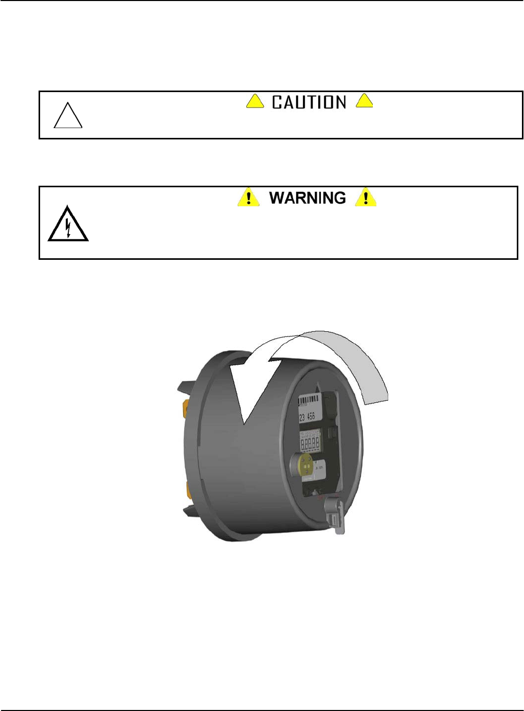
Servicing the iCon APX Meter Replacement – Basic Components
Replacement of the Meter Cover
It is strongly recommended that all replacement procedures for component-level repairs be done
in the shop. Removal of the Meter Cover in the field may allow debris or other contaminants into
the meter, damaging the meter or causing further damage to a malfunctioning meter.
Removal of the Meter Cover in the field may allow debris or other contaminants into the
meter, further damaging the meter or causing the meter to malfunction.
Removing the Meter Cover
Hazardous voltages are present when power is applied to the meter. Do not remove the
Meter Cover or attempt to disassemble the metering equipment while power is applied.
Failure to observe this warning exposes personnel to the risk of death or serious injury and
risks damage to the equipment.
1. If the APX meter is in a test socket, ensure the power has been removed from the socket.
2. Remove the meter from the test socket.
3. Remove the T-Bar Seal from the meter.
4. Grasp the Meter Cover, and turn it counter-clockwise until it reaches a positive stop.
Figure 4-1: Removing the Meter Cover
5. Remove the Meter Cover from the Meter Base Assembly.
Version 1.0 Servicing the iCon APX Meter 4-5
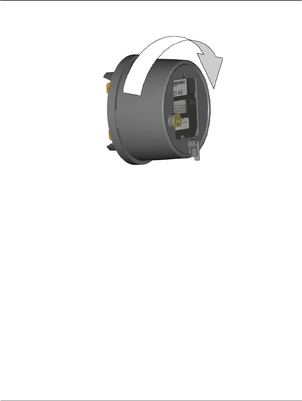
Replacement – Basic Components Servicing the iCon APX Meter
4-6 Servicing the iCon APX Meter TM-iX0A-0805
Installing the Meter Cover
1. Reseat the Meter Cover into the Meter Base Assembly
2. Turn the Meter Cover clockwise until it reaches a positive stop.
Figure 4-2: Installing the Meter Cover
3. Install a new T-Bar Seal.
4. Install a new Demand Reset Seal.
Replacement of the Register Cover
The instructions in this section provide the necessary steps required to replace the Register
Cover.
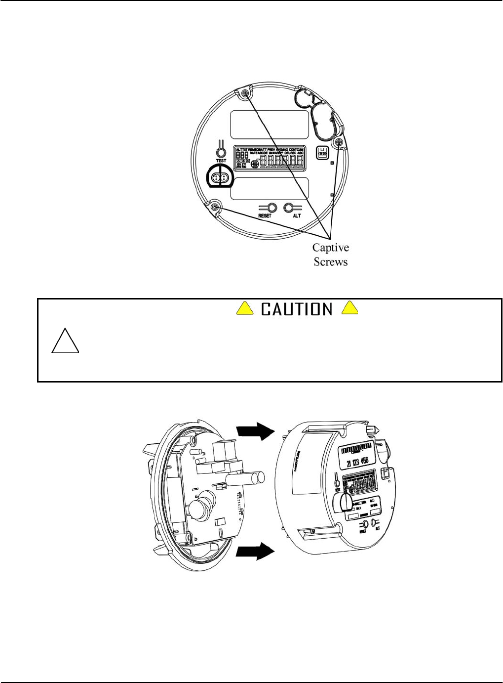
Servicing the iCon APX Meter Replacement – Basic Components
Removing the Register Cover
1. Remove the Meter Cover. Refer to “Removing the Meter Cover” above.
2. Loosen the three (3) captive screws that secure the Register Cover to the Meter Base
Assembly so they are no longer engaged in the Base Assembly.
Figure 4-3: Register Cover – Captive Screws
The APX meter design provides a secure fit of the Interconnect Board into the Sensor
Board connector port. When removing the Register Cover, it may be necessary to gently
rock the Register Cover from top to bottom to extract the Interconnect Board pins from the
Sensor Board connector port. Use care not to over-extend the pins. Failure to observe this
caution may result in damage to the meter.
3. Carefully remove the Register Cover from the Meter Base Assembly to expose the internal
components.
Figure 4-4: Register Cover – Removal
Version 1.0 Servicing the iCon APX Meter 4-7

Replacement – Basic Components Servicing the iCon APX Meter
4-8 Servicing the iCon APX Meter TM-iX0A-0805
Installing the Register Cover
1. Hold the Register Cover at a slight angle as shown in Figure 4-5.
2. Align the Interconnect Board with the associated connector on the Sensor Board.
3. Align the Captive Screw Slot with the opening in the Sensor Board.
Figure 4-5: Installing the Register Cover
4. Tip the Register Cover down onto the Meter Base Assembly
5. Press the Register Cover firmly into the Meter Base Assembly until the Interconnect Board
is firmly seated on the Sensor Board.
Use care not to over-tighten the captive screws. Failure to observe this Caution may result
in damage to the bosses in the Meter Base.
6. Securely tighten the Captive Screws to five (5) in-lb of torque.
7. Install the Meter Cover. Refer to “Installing the Meter Cover” above.
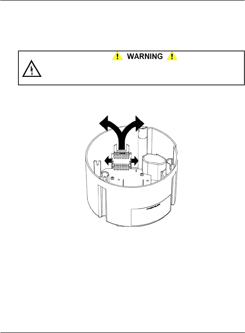
Servicing the iCon APX Meter Replacement – Basic Components
Replacing the Interconnect Board
This section provides the instructions necessary to replace the Interconnect Board.
Removing the Interconnect Board
1. Remove the Register Cover. Refer to “Removing the Register Cover” above.
The Register Display Board and Register Cover may contain sharp edges. Exercise care
while removing the Interconnect Board. Do not overextend the Integrated Alignment Ribs.
Failure to observe this warning may result in minor injury to personnel and damage to
equipment.
2. Gently push the top of the left Integrated Alignment Rib to the left and pull the Interconnect
Board up and to the right.
3. Gently push the top of the right Integrated Alignment Rib to the right and pull the
Interconnect Board up and to the left.
Figure 4-6: Removing the Interconnect Board
4. Repeat Step 2 and Step 3, slowly working the Interconnect Board from side to side until it
is free of the Register Display Board connector.
Version 1.0 Servicing the iCon APX Meter 4-9
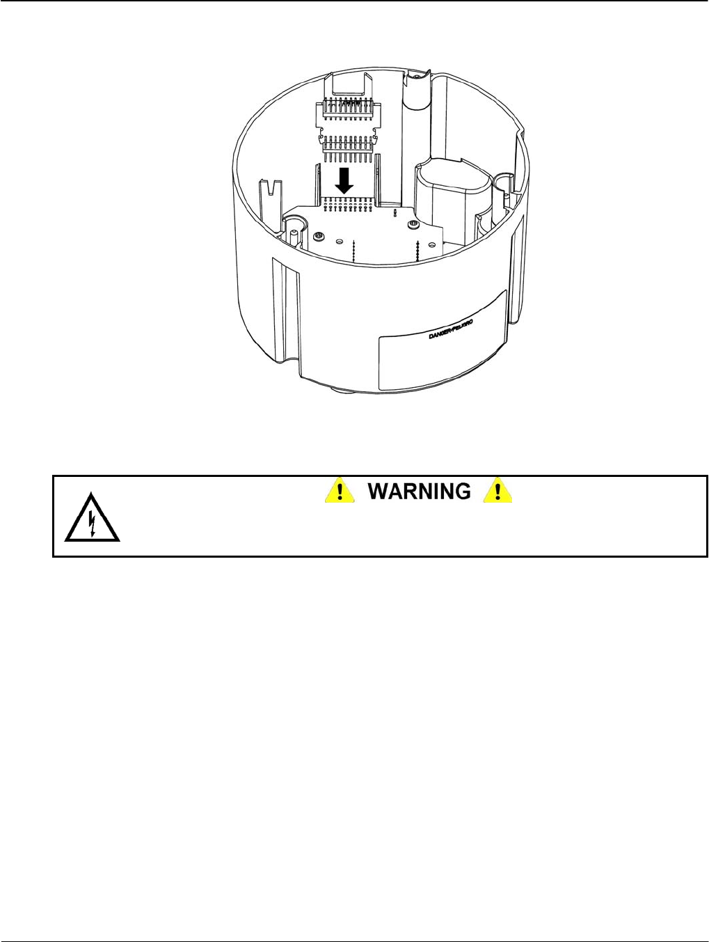
Replacement – Basic Components Servicing the iCon APX Meter
4-10 Servicing the iCon APX Meter TM-iX0A-0805
Installing the Interconnect Board
1. Slide the Interconnect Board into the Integrated Alignment Ribs.
Figure 4-7: Installing the Interconnect Board
2. Align the Header Pins on the Interconnect Board with the connector on the Register Display
Board.
The Register Display Board, Register Cover, and Interconnect Board may contain sharp
edges. Exercise care while installing the Interconnect Board. Failure to observe this
warning may result in minor injury to personnel.
3. Gently press the Interconnect Board into the connector on The Register Display Board until
the board clicks into place.
4. Install the Register Cover. Refer to “Installing the Register Cover” above.
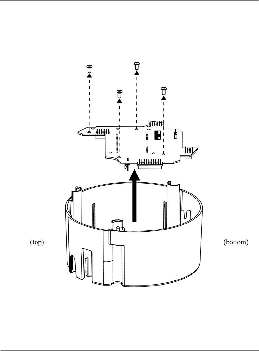
Servicing the iCon APX Meter Replacement – Basic Components
Replacing the Register Display Board
This section contains instructions for replacing the Register Display Board.
Removing the Register Display Board
1. Remove the Interconnect Board. Refer to “Removing the Interconnect Board” above.
2. Remove the screws securing the Register Display Board to the Register Cover.
Figure 4-8: Removing the Register Display Board
3. Carefully lift the display board out of the Register Cover.
Version 1.0 Servicing the iCon APX Meter 4-11
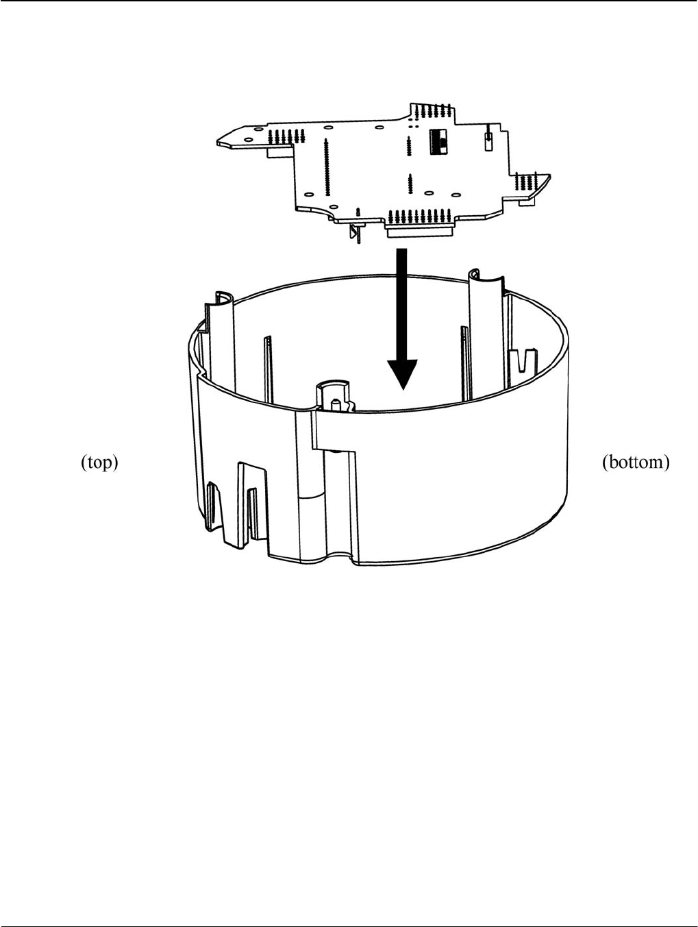
Replacement – Basic Components Servicing the iCon APX Meter
4-12 Servicing the iCon APX Meter TM-iX0A-0805
Installing the Register Display Board
1. Align the LCD with the rectangular opening in the Register Cover.
2. Insert the Register Display Board into the Meter Base Assembly as shown in Figure 4-9.
Figure 4-9: Installing the Register Display Board
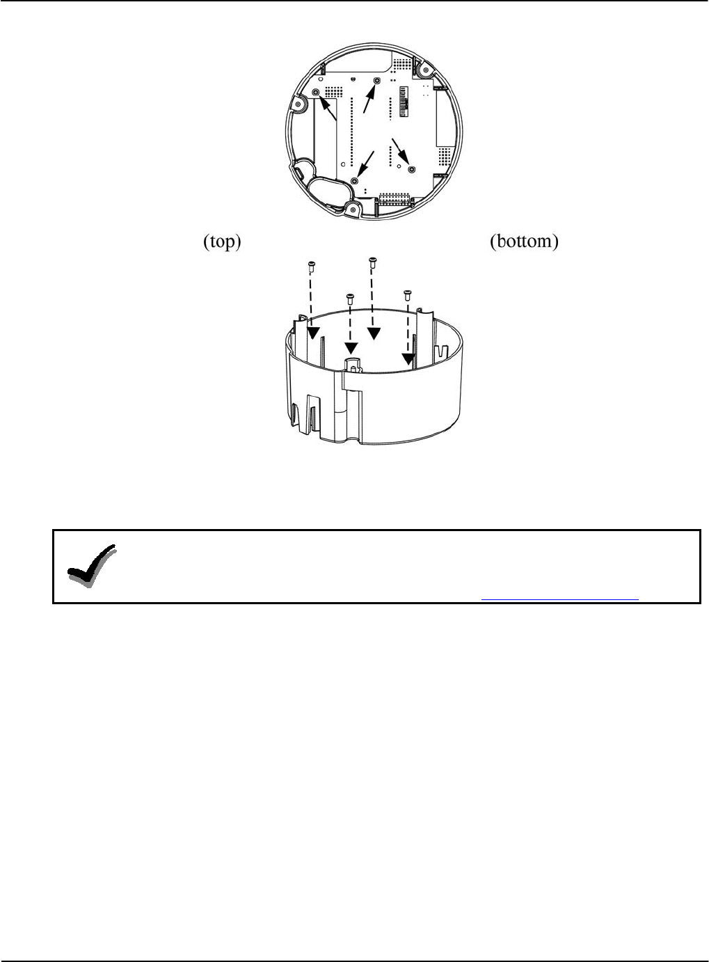
Servicing the iCon APX Meter Replacement – Basic Components
Version 1.0 Servicing the iCon APX Meter 4-13
3. Locate the four (4) holes for the screws.
4. Secure the display board to the Register Cover using the four (4) screws.
Figure 4-10: Installing the Register Display Board Screws
5. Install the Interconnect Board. Refer to “Installing the Interconnect Board” above.
6. Install the Register Cover. Refer to “Installing the Register Cover” above.
NOTE
If the meter continues to malfunction, the error may be in the Sensor Board or other meter
component. Do not replace the Sensor Board. Contact your sales representative and
Customer Service at Sensus Metering Systems. Refer to Sensus Metering Systems.
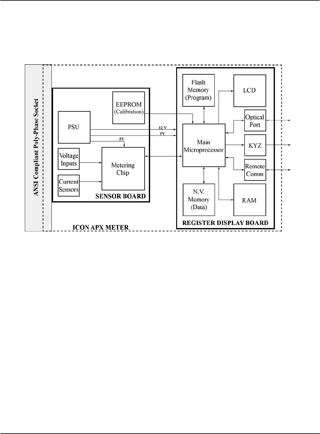
Theory of Operation
Metrology
Version 1.0 Theory of Operation 5-1
Chapter 5
This chapter describes the theory of operation for the iCon™ APX Advanced Functionality
meter. Figure 5-1 supplements the information contained in this section.
Figure 5-1: APX Meter Operational Overview
Metrology
The APX meter performs certain operations on the power present at the socket to provide
accurate measurements. Metrology for power consumption consists of:
• Sensors
• Input
• Power Calculations
• Data Transfer
Sensors
The APX meter contains a current and voltage sensors for power measurement.
Current Sensor
Current is measured using proprietary Sentec® technology. There is one sensor for each phase,
and these sensors interface with the Metering Chip by means of three precision amplifiers.

Metrology Theory of Operation
5-2 Theory of Operation TM-iX0A-0805
Voltage Sensor
Voltage on each phase is measured using a precision-resistive-divider that is designed to
maintain a highly stable division ratio over temperature, humidity, and time. The signals from
the divider feed into the Metering Chip.
Inputs
The two types of meter data are:
• Real-time values (instantaneous), such as per-phase voltages and currents
• Accumulated values, such as kWh
Depending on meter form, up to six inputs (Va, Vb, Vc, Ia, Ib, and Ic) are simultaneously
sampled at a rate of 26k samples/second at 24-bit resolution. The sample streams:
• Are filtered
• Corrected for gain and offset
• Serve as the real-time values for the calculations of per-phase and poly-phase energy (Wh,
VARh, and VAh)
The calculated energy values are accumulated in the designated energy registers, and are used to
generate the test pulse signals. The Kh (configured through iConFig) setting controls the weight
of each pulse. The test pulse signals are routed to the IR Test Pulse LED under the control of the
main microprocessor.
Power Calculations
The real-time and accumulated values are used in the calculations to determine:
• Watts and Watt-hours
• kVA and kVAR
Watts and Watt-Hours
The Metering Chip multiplies the real-time values of current and voltage to calculate power
(kW), and accumulates kW over time as energy (kWh). This calculation includes digital
calibration factors to ensure that the registration of the meter is kept within specified tolerances.
The raw energy values for each individual phase are transmitted by digital serial interface to the
Register Display Board. The interface also carries information on the RMS current and voltage
for each phase. The values are interrogated by the Register Display Board at least once per
line cycle.

Theory of Operation Register Display Board
kVA/kVAR Calculations
The Metering Chip calculates a +90 degree, phase-shifted current signal. The result is multiplied
by the voltage signal to calculate reactive power (kVAR). The accumulation of reactive power
over time provides the reactive energy (kVARh) measurement.
The Metering Chip measures the instantaneous RMS current and voltage signals and multiplies
them together to create apparent power (arithmetic) samples. These samples are then
accumulated over time to provide the apparent energy (kVAh) measurement (arithmetic).
The meter’s main processor on the Register Display Board calculates vectorial kVAh using a
vector calculation based on kWh and kVAR values.
Data Transfer
Twice per line cycle, the meter’s main processor reads the data from all of the metrology energy
registers. This data is parsed, distributed, and accumulated in registers located on the
Register Display Board.
Once per second, the parsed data stored on the Register Display Board is transferred to
high-level tasks running on the processor’s real-time operating system. This parsed data is used
to:
• Calculate demands
• Update total billing, Time-of-Use registers (when enabled), and Load Profile
• Determine if alarm thresholds, such as Demand Thresholds and/or Reverse Power
Thresholds, have been exceeded
Calibration
The Sensor Board contains a serial EEPROM that stores the calibration constants of the sensors.
These constants are determined during the initial calibration of the meter.
Register Display Board
Main Microprocessor
Firmware running in flash memory on a 32-bit, ARM7 (RISC) processor performs the advanced,
high-level functions within the meter. The functions include:
• Processing and storage of data from metrology
• Displaying data on the LCD
• Communicating:
▪ Internally with metrology
▪ Externally by way of optional AMR modules
▪ Externally by way of the integral optical port
• Monitoring and acting on activations of switches on the face of the meter
• Maintaining time and calendar functions
• Keeping status information updated
• Maintaining a historical log of events
Version 1.0 Theory of Operation 5-3
Power Supply Theory of Operation
5-4 Theory of Operation TM-iX0A-0805
Non-Volatile Memory
Special algorithms have been employed to ensure the long-term validity of the data stored in
256 KB of flash memory. This memory is used to store all non-volatile data such as:
• Meter configuration (iConFig created meter Program)
• Billing data
• Load Profile data
• Status data
Power Supply
The power supply is a wide-range, switch-mode supply that is designed to operate from a
poly-phase supply. However, in the event of an outage on one or two phases, the power supply
continues operating. Some functionality may be inhibited under these circumstances, depending
on the option boards fitted to the meter and the service type/voltage. Refer to Appendix B:
Specifications for details of operating voltage ranges.
Demand Metering
Demand
Demand is calculated over an interval of time. Intervals can be configured but must be factors of
60 minutes (1, 2, 3, 5, 6, 10, 12, 15, 30, and 60). The Demand interval and subinterval lengths
(See “Sliding” below.) are configured using iConFig.
A new demand interval begins when the demand interval is changed or when entering or exiting
Test Mode. The number of minutes remaining in the current subinterval is available for display.
The EOI Annunciator temporarily illuminates at the end of each subinterval.
The meter calculates and stores the peak Demand for each energy value (kWh, kVARh, kVAh).
The meter also stores either the Cumulative or Continuously Cumulative Demand.
The meter can calculate Block Demand and Sliding (Rolling) Demand (kW, kVA, kVAR).
Block
NOTE:
To configure the meter for Block Demand, the subinterval is set to the same length of time
as the interval length.
Block Interval Demand is where the interval and subinterval are the same value. Dividing 60 by
the interval length and then multiplying the quotient by the measured Demand gives you Block
Demand.
EXAMPLE: If the interval length is 30 minutes and the measured energy is 100 kWh, then:
60 ⁄ Interval Length * Measured Energy = Block Demand
60 ⁄ 30 * 100 kWh = 200 kWh
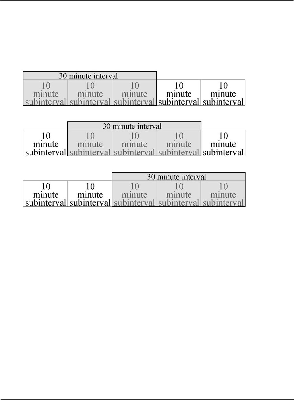
Theory of Operation Demand Metering
Sliding
Sliding (Rolling) Demand is where intervals are divided into a fixed number of subintervals.
Demand calculations are performed at the end of each subinterval instead of at the end of each
interval.
As in Block Demand, the interval length must be a factor of 60. The subinterval length must be a
factor of the interval. Figure 5-2 is an example of an interval of 30 minutes with 10-minute
subintervals. Demand is calculated every 10 minutes based upon the three previous subintervals.
Figure 5-2: Sliding Demand Interval
Peak
Peak Demand is stored as part of the billing quantities in the billing registers. It is the maximum
calculated Demand since the last Demand Reset.
Cumulative
Cumulative Demand is stored as part of the billing quantities in the billing registers. It is the sum
of the previous billing period peak Demand readings. At the time of a Demand Reset, the
maximum Demand for the most recent billing period is added to the previously accumulated total
of all maximum Demands.
Continuous Cumulative
Continuous Cumulative Demand is stored as part of the billing quantities in the billing registers.
It is the sum of the previous billing period peak Demands and the present period peak Demand.
Demand Reset
When the meter performs a Demand Reset, the meter:
• Adds the present Demand values to the Previous Demand register
• Resets the intervals back to the beginning
• Resets the Demand registers to zero (0)
Version 1.0 Theory of Operation 5-5

Demand Metering Theory of Operation
5-6 Theory of Operation TM-iX0A-0805
Outage Recognition
The meter can detect temporary interruptions in service. For Demand calculations, meters
without Real-Time-Clocks (RTCs) “recognize” all interruptions in service as outages. Meters
with RTCs can be configured to only “recognize” outages if they last more than the configured
number of seconds. The Outage Recognition Time is configurable using iConFig.
Demand Forgiveness Time
Demand Forgiveness Time is the configured amount of time immediately following a recognized
power outage that Demand calculations are suspended. The Demand Forgiveness Time is
configurable using iConFig.
Self Read
During a Self Read, the meter captures the current billing data and then stores it in the associated
Self Read registers.
Self Reads are events that can be configured to be:
• Scheduled to occur at specific times or intervals
• Performed when other events occur (i.e., during a Demand Reset)
• Performed when triggered by an external command
Coincident Values
Coincident demand refers to a demand value that occurs at the same time as another demand
reaches its peak value. For example, an electric utility may want to record the kVAR demand at
the time of a maximum kW demand. This requires that kVAR demand be stored and reported
during the same interval as the maximum kW demand. Similarly, coincident power factor refers
to a power factor that occurs at the same time as a demand value reaches its peak value. For
example, an electric utility may want to record the average power actor at the time of a
maximum kVAR demand. This requires the average power factor be stored and reported during
the same interval as the maximum kVAR demand.
Primary/Secondary Metering
Primary Metering applies to transformer rated meters. Measured energy values are scaled
according to the current transformer (CT) and primary transformer (PT) ratios of the current
and/or voltage transformers connected to the meter. The resultant values reflect the energy as if
the meter was on the primary side of the transformers.
With Secondary Metering, the energy values are not scaled (i.e., the actual energy flowing
through the meter is measured).
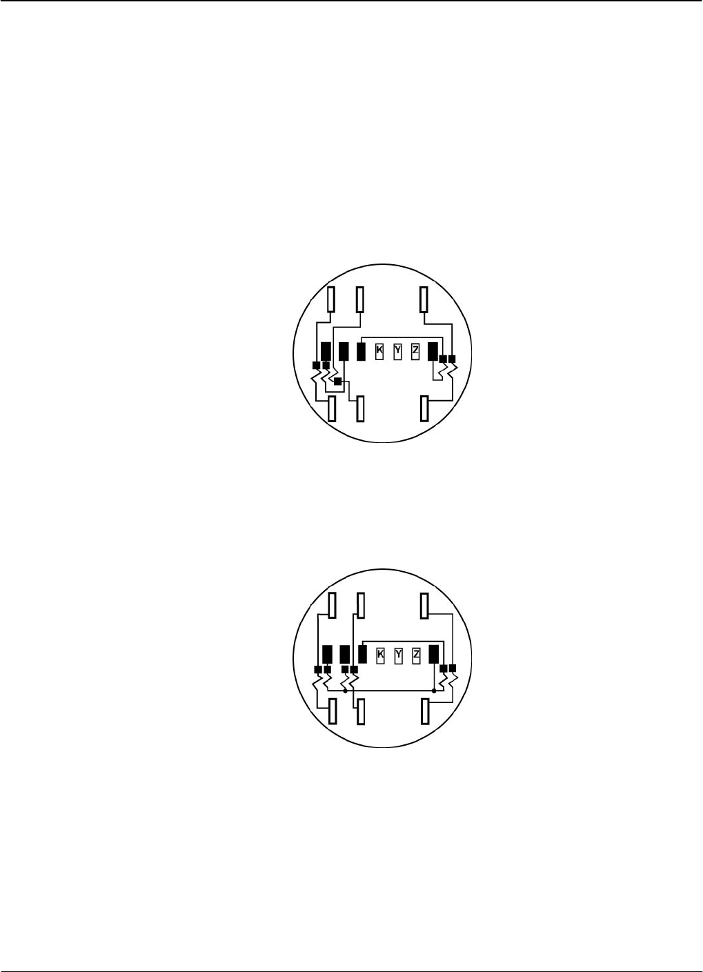
Socket Wiring
Form 8S
Version 1.0 Socket Wiring A-1
Appendix A
This appendix provides meter and ANSI compliant socket specifications.
Form 8S
The standard connections for the iCon™ APX Advanced Functionality Meter are made with
blades that pass through the Meter Base into ANSI compliant sockets.
Figure A-1 shows the socket wiring for a two-element, transformer-rated, three-phase, four-wire
socket for Delta service connections.
Figure A-1: Socket Wiring - Form 8S
Form 9S
Figure A-2 shows the socket wiring for a three-element, transformer-rated, three-phase, four-wire
socket for Wye service connections.
Figure A-2: Socket Wiring - Form 9S
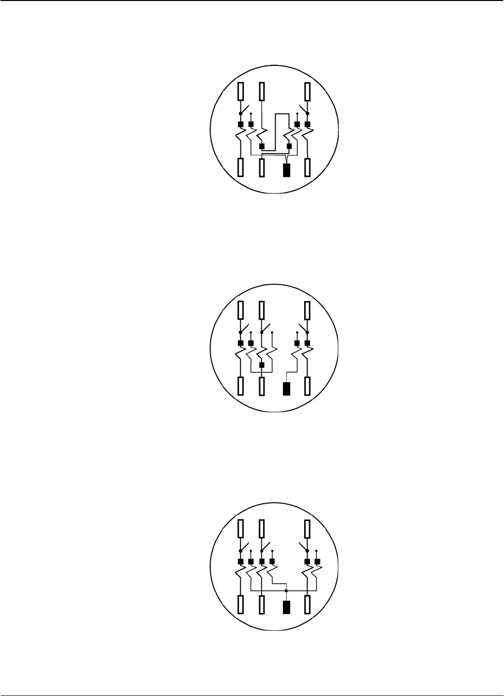
Form 14S Socket Wiring
A-2 Socket Wiring TM-iX0A-0805
Form 14S
Figure A-3 shows the socket wiring for a two-element, self-contained, three-phase, four-wire
socket for Wye service connections.
Figure A-3: Socket Wiring - Form 14S
Form 15S
Figure A-4 shows the socket wiring for a two-element, self-contained, three-phase, four-wire
socket for Delta service connections.
Figure A-4: Socket Wiring - Form 15S
Form 16S
Figure A-5 shows the socket wiring for a three-element, self-contained, three-phase, four-wire
socket for Wye service connections.
Figure A-5: Socket Wiring - Form 16S

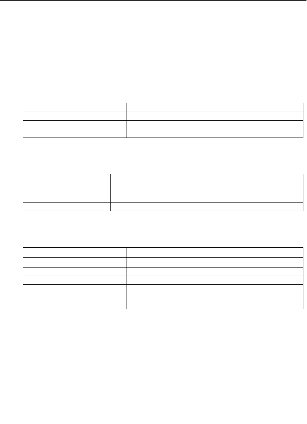
Specifications
Meter Specifications
Version 1.0 Specifications B-1
Appendix B
This appendix provides meter and ANSI compliant socket specifications.
Meter Specifications
Operating
Table B-1: Operating Conditions
Voltage 120 – 480 (96 – 576) VAC
Current 0 to Class Amperes
Rated Frequency 45 – 65 Hz
Ambient Temperature 25°C ± 5°C (77°F ± 9°F)
Environmental
Table B-2: Environmental Conditions:
Temperature
Storage
Operating
-40°C to +85°C (-40°F to 185°F)
-30°C to +55°C (-22°F to 131°F)
Humidity 0 to 95% RH (non-condensing)
Maximums
Table B-3: Maximums
ANSI C37.90.1 2.5kV, 2500 strikes (Oscillatory)
ANSI/IEEE 62.41 6kV, @1.2/50µs, 10 strikes (High Voltage Line Surge
IEC 61000-4-4 4kV, 2.5kHz repetitive burst for 1 minute (Burst)
ANSI C12.1-2001 sec 4.7.3.1 2.5kV, 60Hz, for 1 minute (Insulation)
Current 120% Class Amperes Continuous
200% Class Amperes 1 Second
Voltage 576 VAC (Phase-to-Phase)
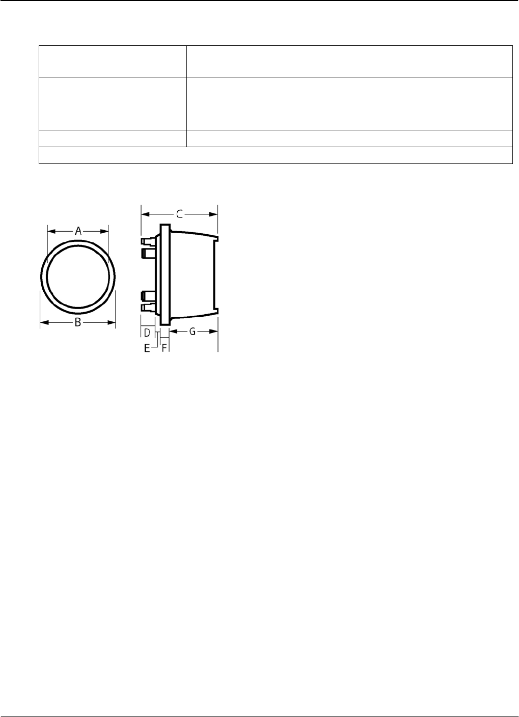
Meter Specifications Specifications
B-2 Specifications TM-iX0A-0805
Input
Table B-4: Input Specifications
Starting Current 5mA for Class 20
50mA for Class 200
*Power Supply Burden 120V 2.2W 3.5VA
240V 2.8W 6.6VA
277V 2.4W 6.8VA
Current Circuit Burden < 0.25 VA per phase at Test Amperes
* - Input voltage measured phase to Neutral.
Physical Dimensions
Dimensions
A B C D E F G
in 6.45 6.95 5.0 0.91 0.27 0.55 3.31
cm 16.38 17.65 12.80 2.31 0.69 1.40 8.41
Shipping Weight
1 Meter Carton 2.6 lbs 1.2 kg
4 Meter Cartons 10.1 lbs 4.6 kg
96 Meter Pallet 278.4 lbs 126.3 kg
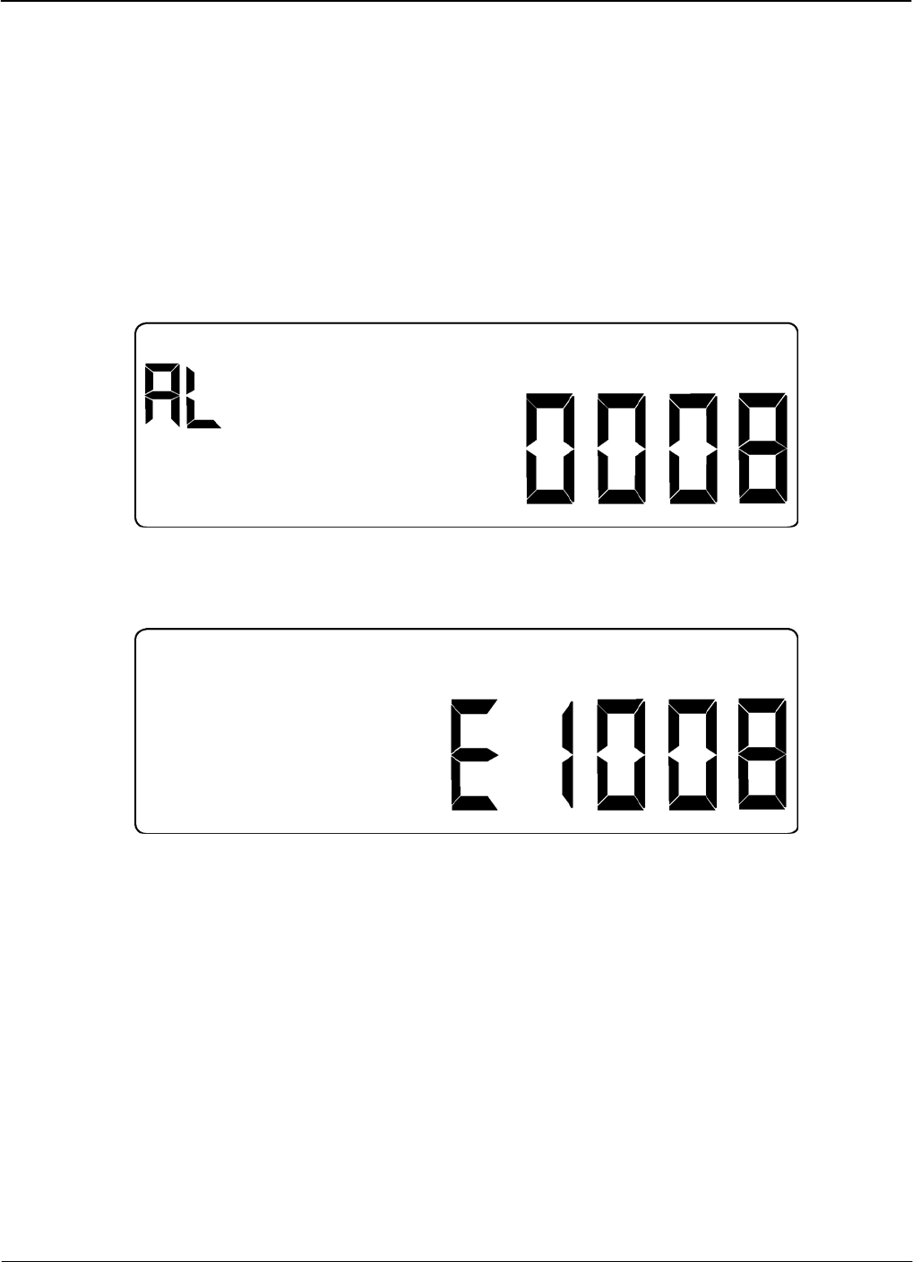
Alarms, Diagnostics, and Errors
Codes
Version 1.0 Alarms, Diagnostics, and Errors C-1
Appendix C
The tables in this appendix outline the codes for alarms and errors within the meter. Many of the
codes can be configured by iConFig™ to be displayed on the meter’s LCD should certain
conditions or events occur. Refer to iConFig Set-up and User’s Guide for configurable alarms and
thresholds.
Certain conditions are detected by the meter and may be accompanied by one or more codes that
aid the technician in troubleshooting the situation. In the event the meter detects an alarm
condition, a code similar to the one shown in. Figure C-1 is displayed.
Figure C-1: Alarm Code Example
In the event the meter detects an alarm condition, a code similar to the one in Figure C-2 is
displayed.
Figure C-2: Error Code Example
Codes
The following tables provide the code numbers, descriptions, notes, and corrective actions (if any)
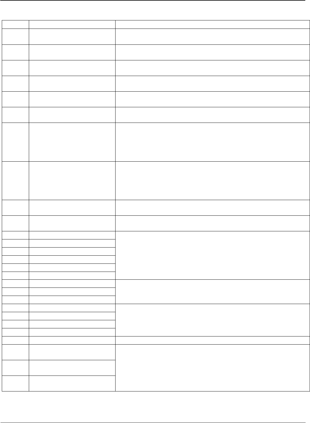
Codes Alarms, Diagnostics, and Errors
C-2 Alarms, Diagnostics, and Errors TM-iX0A-0805
Alarm
Codes Description Notes/Corrective Action
0008 Unprogrammed No Program is present in the meter.
Download a Program into the meter.
0013 Non-Volatile Memory Error Meter memory is corrupted.
Contact technical support.
0014 RTC Error Real-Time-Clock (RTC) is malfunctioning.
Backup all of the meter data and contact technical support.
0016 Low Battery The battery is not working properly.
Replace the battery.
0021 Reverse Rotation Detected
(poly-phase)
Energy was received from the load side of the meter.
No corrective action required.
0072 Register Overflow Power down, and then power up the meter.
If the error message remains, contact technical support.
0073 Last Demand Interval
Restore Failed
The meter was unable to resume calculating Demand with the
interval data that was saved during shutdown. A new interval was
started.
No corrective action required, If the condition persists, contact
technical support.
0074 Last Load Profile Interval
Restore Failed
The meter was unable to resume calculating Load Profile with the
interval data that was saved during shutdown. A new interval was
started.
No corrective action required, If the condition persists, contact
technical support.
0075 Modem Error Modem may be malfunctioning.
Contact technical support.
0080 Calibration Error –
E2 Corrupt
The meter detected an anomaly with the calibration constants.
Return the meter to the vendor.
0088 Demand Overload Tier A
0089 Demand Overload Tier B
0090 Demand Overload Tier C
0091 Demand Overload Tier D
0092 Demand Overload Tier E
0093 Demand Overload Total
The user configures the meter to monitor these thresholds.
Corrective actions are determined by the utility’s standard
procedures.
0096 Phase A Missing Volts
0097 Phase B Missing Volts
0098 Phase C Missing Volts
The user configures the meter to monitor these thresholds.
Corrective actions are determined by the utility’s standard
procedures.
0099 Phase A Missing Current
0100 Phase B Missing Current
0101 Phase C Missing Current
0104 Neutral Current Overload
The user configures the meter to monitor these thresholds.
Corrective actions are determined by the utility’s standard
procedures.
0106 Bad Element Detected If the meter connections are good, contact technical support.
0107 Reverse Rotation Phase A
Detected
0108 Reverse Rotation Phase B
Detected
0109 Reverse Rotation Phase C
Detected
The user configures the meter to monitor these thresholds.
Corrective actions are determined by the utility’s standard
procedures.
Alarms, Diagnostics, and Errors Codes
Version 1.0 Alarms, Diagnostics, and Errors C-3
Alarm Codes - continued
Codes Description Notes/Corrective Action
0112 Low Current Phase A
0113 Low Current Phase B
0114 Low Current Phase C
0115 Low Current (System)
The user configures the meter to monitor these thresholds.
Corrective actions are determined by the utility’s standard
procedures.
0116 High Current Phase A
0117 High Current Phase B
0118 High Current Phase C
0119 High Current (System)
The user configures the meter to monitor these thresholds.
Corrective actions are determined by the utility’s standard
procedures.
0120 Low Voltage Phase A
0121 Low Voltage Phase B
0122 Low Voltage Phase C
0123 Low Voltage (System)
The user configures the meter to monitor these thresholds.
Corrective actions are determined by the utility’s standard
procedures.
0124 High Current Phase A
0125 High Voltage Phase B
0126 High Voltage Phase C
0127 High Voltage (System)
The user configures the meter to monitor these thresholds.
Corrective actions are determined by the utility’s standard
procedures.
0128 Low Leading PF Phase A
0129 Low Leading PF Phase B
0130 Low Leading PF Phase C
0131 Low Leading PF (System)
The user configures the meter to monitor these thresholds.
Corrective actions are determined by the utility’s standard
procedures.
0132 High Leading PF Phase A
0133 High Leading PF Phase B
0134 High Leading PF Phase C
0135 High Leading PF (System)
The user configures the meter to monitor these thresholds.
Corrective actions are determined by the utility’s standard
procedures.
0136 Voltage Sag Phase A
0137 Voltage Sag Phase B
0138 Voltage Sag Phase C
0139 Voltage Sag (System)
The user configures the meter to monitor these thresholds.
Corrective actions are determined by the utility’s standard
procedures.
0140 Voltage Swell Phase A
0141 Voltage Swell Phase B
0142 Voltage Swell Phase C
0143 Voltage Swell (System)
The user configures the meter to monitor these thresholds.
Corrective actions are determined by the utility’s standard
procedures.
0144 AMR Module Error The AMR module has reported an error to the meter.
Refer to the documentation that accompanied the module.
0145 AMR Communication Error
The AMR module is no longer communicating with the meter.
Reseat the module. If the condition persists, contact technical
support.
Codes Alarms, Diagnostics, and Errors
C-4 Alarms, Diagnostics, and Errors TM-iX0A-0805
Diagnostic
These diagnostics can turned On or Off with iConFig. The diagnostics are designed to assist the
technicians and installers in diagnosing any error conditions within the meter and the service at the
socket.
Codes Description Notes/Corrective Action
0001 Diagnostic 1 (Polarity/Cross
Phase)
The meter has detected a connection that is reversed.
Check the socket wiring at the meter and/or transformer.
0002 Diagnostic 2 (Phase
Voltage Deviation)
The meter has detected one or more service voltages outside of the
configured nominal percentage.
Check the socket wiring at the meter and CT/PT ratios.
0003 Diagnostic 3 (Inactive
Phase Current)
Current on one or more of the phases is missing.
Check the socket wiring at the meter for each phase.
0004 Diagnostic 4 (Phase Angle
Displacement)
The power factor of one or more of the phases is out of tolerance.
Check the socket wiring at the meter for each phase.
0006 Diagnostic 6 (Current
Magnitude/Imbalance)
Too much load current flowing to the meter and/or one or more of
the phase currents are out of tolerance relative to the other phases.
Check the connections to the load and load-side wiring.
0007 Diagnostic 7 (Energy
Direction)
The power flowing through the meter is reversed.
Check the socket wiring at the meter or for a generator on the load
side of the meter.
Error
The following error codes indicate that the meter is not functioning improperly. Contact technical
support to report the error code.
Codes Description
1001 RAM Failure
1002 Flash Checksum
1003 Flash Empty
8841 Metrology Error
8904 Metrology Error
8905 Metrology Error
8C04 Metrology Error
8C05 Metrology Error
9001 RTC Error
9002 RTC Error
9003 RTC Error
9004 RTC Error
9005 RTC Error
9006 RTC Error
9007 RTC Error
9011 RTC Error
9012 RTC Error
9013 RTC Error
9014 RTC Error
9021 RTC Error
9022 RTC Error
9023 RTC Error

Alarms, Diagnostics, and Errors Codes
Version 1.0 Alarms, Diagnostics, and Errors C-5
Error Codes - continued
Codes Description
9101 RTC Error
9102 RTC Error
9103 RTC Error
9104 RTC Error
9111 RTC Error
9201 RTC Error
9202 RTC Error
9203 RTC Error
9306 Invalid NVRAM Version
9307 NVRAM Data Restore Error
930A NVRAM firmware version upgrade
9601 Outage Interrupt Error
9602 Outage Interrupt Error
9603 Outage Interrupt Error
9604 Outage Reset Exception
9605 Undefined Instruction
9606 Software Interrupt Exception
9607 Pre-fetch Data Exception
9608 Data Exception
9609 Data Exception
960A Operating System Error
960B Run Time Error
960C Assert Error
960D Warm Start Error
960E Cold Start Error
960F Watchdog Error
9640 First Critical Section Error
9641 Calendar Error
9642 Summation Error
9643 Primary Value Error
9644 Demand Error
9645 Load Profile 1 Error
9646 Load Profile 2 Error
9647 Core Metering Error
9648 Display Error
9649 Data Error
964A Relay Error
964B Communication Error
964C Startup Error
964D Last Critical Section Error
964E Calculation Error
9650 Overrun Error
9651 Low Power Mode Error
9652 Sleep Timer Error
9653 Reset Error
9655 Configuration Error
9656 Configuration Error

Index
Version 1.0 I-1
Index
1
120, 277, 240, 480 Indicators, 2-12
A
Activating Test Mode Lock, 2-17
ADE7758 Integrated IC Chip, 2-6
Alarm Codes, C-2
ALT Button, 3-5
ALT Tab, 2-8
Alternate Display List, 2-16
Alternate Mode Button, 2-10, 2-13
Annunciators, 2-11, 2-12
ANSI Standards, 1-4
B
Billing Registers, 1-3
Block Interval Demand, 5-4
Buss Bars, 2-6
Buttons
ALT, 3-5
Alternate Mode, 2-10, 2-13
Demand Reset, 2-10, 2-13
RESET, 3-6, 4-4
TEST, 3-5, 3-6
Test Mode, 2-10, 2-13
C
Calculations
kVA, 5-3
kVAR, 5-3
Watt Hours, 5-2
Watts, 5-2
Calibration, 4-3, 5-3
Calibration Check, 3-2
Closing Phantom Load Links, 3-3
Codes
Alarm, C-2
Diagnostic, C-4
Error, C-4
Coincident Values, 5-6
Cold Start, 4-2
Conducting Blades. See Buss Bars
Configuring Meters, 3-8
Connector Ports, 2-6, 2-14
Continuous Cumulative Demand, 5-5
CT Ratio, 3-9
Cumulative Demand, 5-5
Current Circuit Burden, B-2
Current Magnitude Imbalance Check, 3-10
Current Sensor, 5-1
D
Data
Display, 2-13
Identification, 3-9
Transfer, 5-3
Default Kh, 3-3
Demand
Block Interval, 5-4
Coincident, 5-6
Continuous Cumulative, 5-5
Cumulative, 5-5
Forgiveness, 2-15
Forgiveness Time, 5-6
Interval, 2-15, 5-4
Metering, 2-15
Peak, 5-5
Reset, 5-5
Reset Button, 2-10, 2-13
Reset Lockout Period, 2-15
Reset Seal, 2-15, 3-1
Sliding, 5-5
Subinterval, 2-15, 5-4
Diagnostic Checks, 4-3
Diagnostic Codes, C-4
Diagnostic Display List, 2-17
Diagnostic Mode, 2-17
Entering, 2-17
Exiting, 2-18
Diagnostics. See Industry Standard Diagnostics
Diagnostics and Alarms, 3-10
Disk Simulator, 2-13
Display Board Check, 3-5

Error! No text of specified style in document. Index
I-2 Index TM-iX0A-0805
Infrared LED, 2-10, 2-13
Display Lists
Infrared LED Sensor, 2-10, 2-13
Alternate, 2-16
Infrared Port. See IR Port
Diagnostic, 2-17
Input Specifications, B-2
Normal, 2-16, 3-7
Installation, 3-6
Test Mode, 2-16, 3-5
Installation Check, 4-3
Display Mode, 3-6
Installing
Downloading iConFig Programs, 3-8
Interconnect Board, 4-10
E Meter Cover, 4-6
Register Cover, 4-8
Energy Direction Check, 3-10
Register Display Board, 4-12
Entering Diagnostic Mode, 2-17
Interconnect Board, 2-14
Environmental Contitions, B-1
Installing, 4-10
Error Codes, C-4
Removing, 4-9
Exiting
Internal Components, 2-2
Diagnostic Mode, 2-18
Intervals
Test Mode Lock, 2-17
Block, 5-4
F Sliding, 5-5
IR Port, 4-1
Firmware, 4-1
Communciation Speed, 4-1
Form 14S Socket Wiring, A-2
Optical Probe, 4-1
Form 15S Socket Wiring, A-2
Protocol, 4-1
Form 16S Socket Wiring, A-2
IR Test Pulse LED, 3-3
Form 17S Socket Wiring, A-3
Background, 3-4
Form 8S Socket Wiring, A-1
Location, 3-3
Form 9S Socket Wiring, A-1
Setting the Start-up Delay, 3-4
H
K
Hardware. See Meter Hardware
Kh Calibration Ranges, 3-3
Hardware Setup, 3-1
Kh values, 3-9
Hazardous Voltages, 1-2, 3-2, 4-3, 4-5
Knockouts, 2-5
Hexidecimal Values, 1-3
Kt values, 3-9
History Log Registers, 1-3
History Logs, 3-11 L
Humidity, B-1
Labels
I Danger Label, 2-8, 2-9
FCC Label, 2-8, 2-9
iConFig, 3-8
Nameplate, 2-8
ID Code Display, 2-12
LCD, 2-11
Identification, 3-9
Annunciators, 2-11
Inactive Phase Current Check, 3-10
Displays, 2-11
Industry Standard Diagnostics
Indicators, 2-11
Diagnostic 1, 3-10
LCD Displays and Indicators, 2-12, 2-13
Diagnostic 2, 3-10
LEDs
Diagnostic 3, 3-10
Infrared, 2-13
Diagnostic 4, 3-10
Infrared Sensor, 2-13
Diagnostic 6, 3-10
IR Test Pulse, 3-3
Diagnostic 7, 3-10
Liquid Crystal Display. See LCD

Index
M Meter Specifications
Environmental Contitions, B-1
Maximums, B-1 Input Specifications, B-2
Meter Base Assembly, 2-3, 3-2 Maximums, B-1
Meter Communication, 4-1 Operating Conditions, B-1
Meter Configuration, 3-8 Physical Dimensions, B-2
Meter Cover, 2-14 Metering Chip, 3-4, 5-3
Installing, 4-6 Metering Constants, 3-9
Removing, 4-5 Metrology, 5-1
Meter Hardware, 2-3 Modes
ADE7758 Integrated IC Chip, 2-6 Diagnostic, 2-17, 2-18
Buss Bars, 2-6 Display, 3-6
Connector Ports, 2-6, 2-14 Normal, 2-16
Infrared LED, 2-10 Test, 2-11, 2-13, 3-5
Infrared LED Sensor, 2-10
N
Interconnect Board, 2-14
Knockouts, 2-5 Nameplate, 2-8
LCD, 2-11 Normal Display List, 2-16, 3-7
LCD Annunciators, 2-11
O
LCD Displays, 2-11
LCD Indicators, 2-11 Opening Phantom Load Links, 3-2
Meter Base, 2-3 Operating Conditions, B-1
Meter Base Assembly, 2-3, 3-2 Optical Pick-Up, 3-3
Form 15S/16S, 2-5 Optical Port, 2-10
Form 16S (14S, 15S, 17S), 2-4 Option Board Knockouts. See Knockouts
Form 9S (8S), 2-4 Option Boards, 2-14
Knockouts, 2-5 Outage Recognition, 5-6
Sensor Board, 2-6 Outage Recognition Time, 2-15
Meter Cover, 2-14
P
Metering Chip, 3-4, 5-3
Optical Port, 2-10 Passwords, 2-18
Option Boards, 2-14 Peak Demand, 5-5
Phantom Load, 2-5 Performing a Cold Start, 4-2
Register Cover, 2-8 Permissions, 2-18
Register Cover Assembly, 2-7 Phantom Load, 2-5
Register Display Board, 2-10, 2-14 Phantom Load Links, 3-2, 3-3
Sensing Circuitry, 2-6 Closing, 3-3
Sensor Board, 2-6 Opening, 3-2
Switching Power Supply, 2-6 Phase Angle Displacement Check, 3-10
Meter Multiplier, 3-9 Phase Angles, 3-7
Meter Power-Up, 3-7 Phase Rotation, 3-7
Meter Reset, 4-1 Phase Voltage Deviation Check, 3-10
Polarity and Cross Phase Check, 3-10
Power Supply, 5-4
Previous Demand Registers, 1-3
Primary Metering, 5-6
PT Ratio, 3-9
Version 1.0 I-3

Error! No text of specified style in document. Index
I-4 Index TM-iX0A-0805
Q S
Quadrant Indicators, 2-12 Safety, 1-2
R Safety Precautions, 1-2
Seals
Rated Frequency, B-1 Demand Reset, 2-15, 3-1
Ratios T-Bar, 2-3, 2-15, 3-1
CT, 3-9 Secondary Metering, 5-6
PT, 3-9 Security, 2-18
Register Cover, 2-8 T-Bar Seal, 2-15
Installing, 4-8 Self Read, 5-6
Removing, 4-7 Self-Contained Meters, 3-2
Register Cover Assembly, 2-7 Sensing Circuitry, 2-6
Register Display Board, 2-10, 2-14, 5-3 Sensor Board, 2-6
Installing, 4-12 Sensors
Removing, 4-11 Current, 5-1
Registers Voltage, 5-2
Billing, 1-3 Sensus Metering Systems
History Log, 1-3 Address, I-7
Previous Demand, 1-3 Email Address, 2-2
Status, 1-3 Fax Number, I-7
Test Mode, 3-6 Telephone Number, I-7
Time-of-Use, 5-3 Website Address, 2-14, 4-13, I-7
Remote Communications, 4-1 Service Type, 3-7
Removing Service Voltage, 3-7
Interconnect Board, 4-9 Service Voltage Indicators. See 120, 277, 240,
480 Indicators
Meter Cover, 4-5
Register Cover, 4-7 Sliding Demand, 5-5
Register Display Board, 4-11 Socket Wiring
Replacing Form 14S, A-2
Interconnect Board, 4-9 Form 15S, A-2
Meter Cover, 4-5 Form 16S, A-2
Register Cover, 4-6 Form 17S, A-3
Register Display Board, 4-11 Form 8S, A-1
RESET Button, 3-6, 4-4 Form 9S, A-1
RESET Tab, 2-8 Special Features, 3-11
RESET/ALT Lever, 2-15, 3-1 Standards, 1-4
Resetting the Meter, 4-1 Starting Watts, B-2
Rolling Demand. See Sliding Demand Status Registers, 1-3
Switching Power Supply, 2-6
System Architecture, 2-2

Index
T
Tabs
ALT, 2-8
RESET, 2-8
TEST, 2-8
T-Bar Seal, 2-3, 3-1
Tempratures, B-1
TEST Button, 3-5, 3-6
Test Display List, 2-16
Test Lock, 3-6
Test Mode, 3-5
Button, 2-10, 2-13
Demand Interval, 2-15
Demand Subinterval, 2-15
Display List, 3-5
Registers, 3-6
Test Mode Lock, 2-17
Activating, 2-17
Exiting, 2-17
Test Pulse, 3-6
Test Pulse Kh Outputs, 3-3, 4-3
Test Pulses, 3-3
TEST Tab, 2-8
Theory of Opearation
Block Interval Demand, 5-4
Theory of Operation, 5-1
Demand, 5-4
Power Supply, 5-4
Register Display Board
Main Microprocessor, 5-3
Non-Volatile Memory, 5-4
Time-of-Use Registers, 5-3
Troubleshooting
Display Board Check, 3-5
Installation Check, 4-3
Shop Testing, 4-3
Test Pulse Kh Outputs, 3-3, 4-3
ShopTesting
IR Test Pulse LED, 3-4
Visual Check, 4-2
Missing Seals, 4-2
Physical Damage, 4-2
Tampering, 4-2
U
Updating the Firmware, 4-1
User Defined Tables, 3-11
V
Values
Hexidecimal, 1-3
Ranges, 1-3
Visual Check
Missing Seals, 4-2
Physical Damage, 4-2
Tampering, 4-2
Voltage
Detection, 3-7
Ranges, B-1
Voltage Potential Indicators, 2-12
Voltage Sensor, 5-2
Version 1.0 I-5