Sensus Metering Systems ZIGMOD10 Inline Zigbee Module User Manual FCC Part 15
Sensus Metering Systems Inc. Inline Zigbee Module FCC Part 15
Manual

5015 B.U. Bowman Drive Buford, GA 30518 USA Voice: 770-831-8048 Fax: 770-831-8598
Certification Exhibit
FCC ID: SDBZIGMOD10
IC: 2220A-ZIGMOD10
FCC Rule Part: 15.247
IC Radio Standards Specification: RSS-210
ACS Report Number: 10-0020.W06.11.A
Manufacturer: Sensus Metering Systems, Inc.
Model: ZIGMOD10
Manual

Inline Zigbee Module – User Manual
[FCC ID: SDBZIGMOD10, IC: 2220A-ZIGMOD10]
Revision 2.1, 20 September, 2010
Sensus
Sensus Sensus
Sensus USA
USAUSA
USA
This document contains proprietary information. It may not be copied,
transmitted or distributed, in whole or in part, without the consent of Sensus USA

REVISION SUMMARY
Date Author Change Description
August 14, 2009 BG Baseline
September 15, 2009 JAS Corrected Label information and added label Placement
September 14, 2010 JAS Corrected antenna gain stipulation from 2 to 0dBi.
September 20, 2010 JAS Corrected Label Information and Front Page
Sensus In-Line Zigbee Module – User Manual
3
1.0 Introduction
This document details the installation and usage of the “Sensus In-Line Zigbee
Module”. At present the module is designed to work in the Sensus iConA and
iConAS electric meters although in future in may work with other electric meter
designs.
The module is designed to sit between the sensor board and the display board
within the electric meter. When a Zigbee module is not installed a ribbon cable
connects the sensor and display. In the case when the module is installed the
module is connected between the sensor and display, to give the electric meter
Zigbee functionality.
Sensus In-Line Zigbee Module – User Manual
4
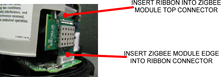
2.0 Installation of the module within an electric meter
First remove the meter outer cover.
Carefully remove the meter inner cover.
Disconnect the ribbon cable from the sensor pcb.
Insert the Zigbee board into the connector that the display ribbon has been
disconnected from.
Insert the free end of the ribbon cable into the connector on the Zigbee module
as shown in Figure 1.
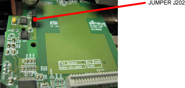
Add the jumper (short) to position J202 on the sensor board, as shown in Figure
2.
Figure 1 – Zigbee module installed in a meter
Sensus In-Line Zigbee Module – User Manual
5
Figure 2 – Jumper must be fitted

Sensus In-Line Zigbee Module – User Manual
6
3.0 Module pin-out description
Pin
Pin Pin
Pin
Number
NumberNumber
Number
Ribbon Connector
Ribbon ConnectorRibbon Connector
Ribbon Connector
Board Edge Connector
Board Edge ConnectorBoard Edge Connector
Board Edge Connector
De
DeDe
Description
scriptionscription
scription
1
11
1
MAINS_SENSE MAINS_SENSE Pass through
2
22
2
RELAY_TRIGGER RELAY_TRIGGER Pass through
3
33
3
RELAY_SWITCH_SENSE RELAY_SWITCH_SENSE Pass through
4
44
4
GROUND EXTRA_CS Ribbon is
grounded. Board
edge is a 5V active
high interrupt line
to the Zigbee
module.
5
55
5
GROUND GROUND Power (Pass
through)
6
66
6
GROUND GROUND Power (Pass
through)
7
77
7
GROUND GROUND Power (Pass
through)
8
88
8
GROUND GROUND Power (Pass
through)
9
99
9
26V_12S 26V_12S 26V from 12S
base (pass
through)
10
1010
10
26V_2S 26V_2S 26V from 2S base
(pass through)
11
1111
11
5V0 5V0 5V supply to the
sensor
12
1212
12
GROUND GROUND Power (Pass
through)
13
1313
13
7759_CF 7759_CF Sensor board
14
1414
14
ZIGBEE IRQ ZIGBEE IRQ Zigbee module
IRQ
15
1515
15
SPI_DATA_OUT SPI_DATA_OUT Sensor SPI Data
Bus

Sensus In-Line Zigbee Module – User Manual
7
16
1616
16
7759_ZX 7759_ZX Sensory Zero
Crossing Indictor
17
1717
17
NOT USED NOT USED
18
1818
18
NOT USED NOT USED
19
1919
19
SPI_CLOCK SPI_CLOCK Sensor SPI Clock
20
2020
20
SPI_DATA_IN SPI_DATA_IN Sensor SPI Data
Appendix A General Statements
Warning: Changes or modifications to this device not expressly approved
by Sensus USA could void the user’s authority to operate the equipment.
NOTE: This equipment has been tested and found to comply with the
limits for a Class B digital device, pursuant to part 15 of the FCC rules.
These limits are designed to provide reasonable protection against harmful
interference in a residential installation. This equipment generates, uses,
and can radiate radio frequency energy and, if not installed and used in
accordance with the instruction, may cause harmful interference to radio or
television reception, which can be determined by turning the equipment off
and on, the user is encouraged to try to correct the interference by one or
more of the following measures:
• Reorient or relocate the receiving antenna
• Increase the separation between the equipment and receiver
• Connect the equipment into an outlet on a circuit different from that to
which the receiver is connected.
• Consult the dealer or an experienced radio/TV technician for help.
Sensus In-Line Zigbee Module – User Manual
8
Appendix B RF Energy Health Hazard
B RF Energy Health HazardB RF Energy Health Hazard
B RF Energy Health Hazard
Please pay attention to the following warnings:
When servicing equipment and selecting a location for the In-Line ZigbeeModule, it is important to
note that a minimum distance of 20 cm (7.9 inches) is required between personnel and ZigBee
Antenna to comply with a radio-frequency exposure limit of 1.0mW/cm
2
.
Professional installation required. The radio equipment described in this guide uses radio
frequency transmitters. Although the power level is low, the concentrated energy from a
directional antenna may pose a health hazard. The ZigBee Module integrated antenna is rated at
a maximum of 0dBi.

Sensus In-Line Zigbee Module – User Manual
9
Appendix C Industry Canada Specific Statements:
The term “IC:” before the radio certification number only signifies that industry Canada
technical specifications were met.
This Class B apparatus meets all the requirements of the Canadian Interference Causing
Equipment Regulations. Operation is subject to the following two conditions: (1) the
device may not cause harmful interference, and (2) this device must accept any
interference received, including interference that may cause undesired operation.
Cet appareil numérique de la classe B répond à toutes les exigences de l’interférence
canadienne causant des règlements d’équipment. L’opération est sujette aux deux
conditions suivantes: (1) ce dispositif peut ne pas causer l'interférences nocive, et (2) ce
dispositif doit accepter n’importe quelle interférence reçue, y compris l’interférence qui
peut causer l’opération peu désirée.
Sensus In-Line Zigbee Module – User Manual
10
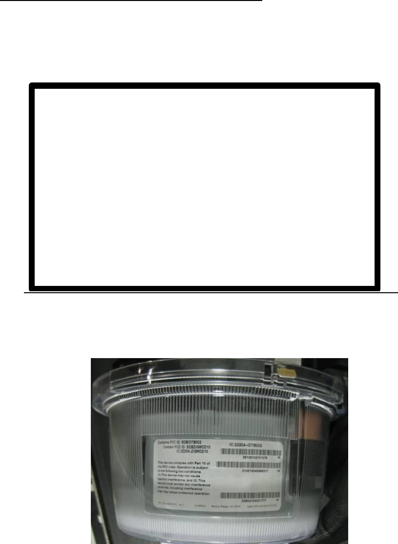
Appendix D Compliance Label and Placement:
The ZigBee host shall display the following label to indicate use of the ZigBee module
within the unit.
Sensus Raleigh, NC 27615
Contains Mod No. ZIGMOD10
Contains FCC ID: SDBZIGMOD10
IC: 2220A-ZIGMOD10
This device complies with Part 15 of the FCC Rules and
Industry Canada Requirements. Operation is subject to the
following two conditions; (1) This device may not cause harmful
interference, and (2) this device must accept any interference
received, including interference that may cause undesired
operation.
Sensus ZigBee Label location on Host Device.