Sensys Traffic RS240 Traffic Sensor User Manual Operation manual
Sensys Traffic AB Traffic Sensor Operation manual
UserManual.wiki
>
Sensys Traffic
>
RS240 User Manual
Operation manual
Navigation menu
Upload a User Manual
Namespaces
Wiki Guide
HTML
PDF
Info
Views
User Manual
Discussion / Help
Navigation
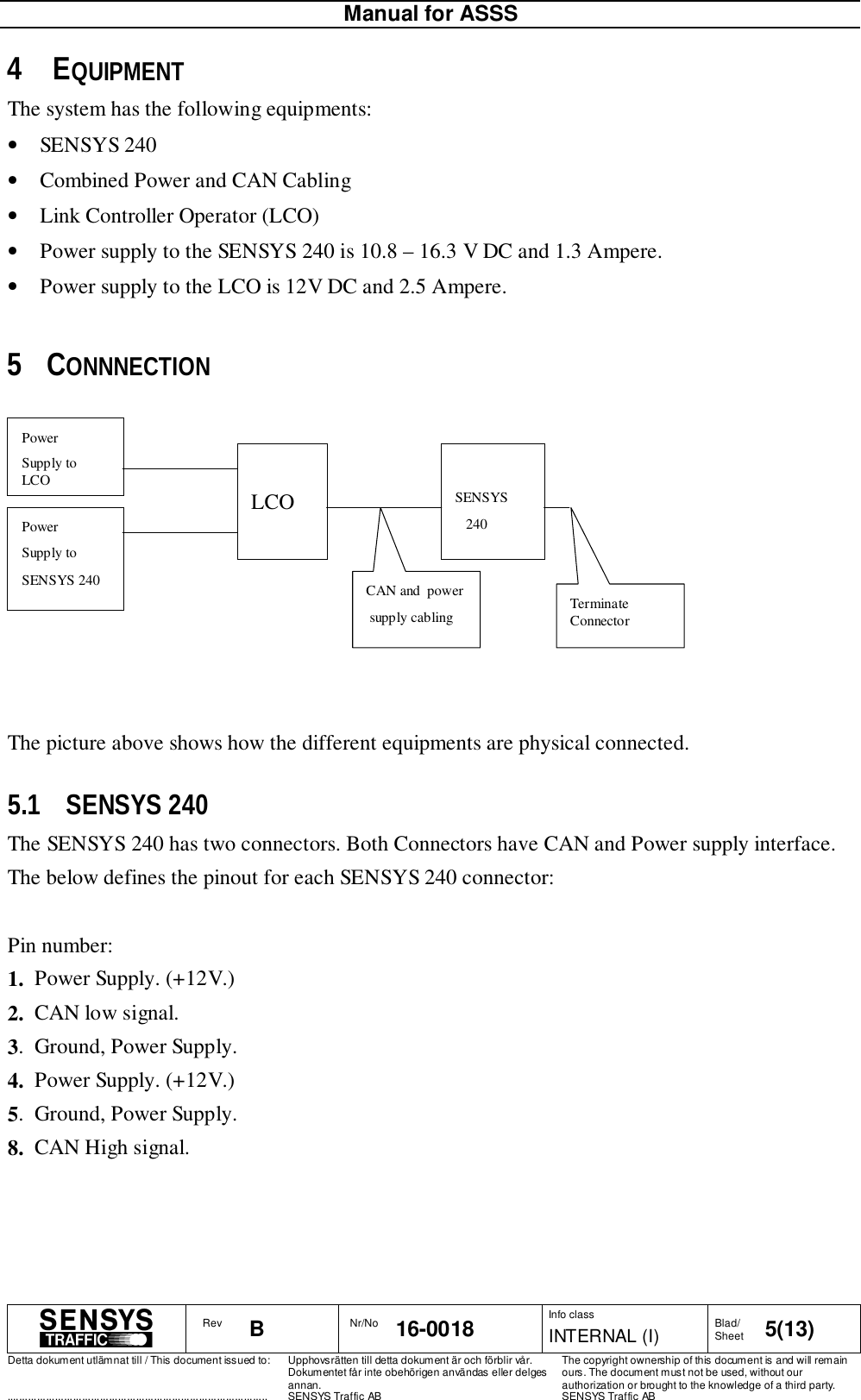
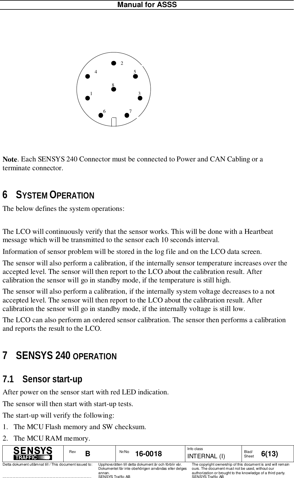
![Manual for ASSSRev B Nr/No 16-0018 Info classINTERNAL (I) Blad/Sheet 4(13)Detta dokument utlämnat till / This document issued to:.......................................................................................Upphovsrätten till detta dokument är och förblir vår.Dokumentet får inte obehörigen användas eller delgesannan.SENSYS Traffic ABThe copyright ownership of this document is and will remainours. The document must not be used, without ourauthorization or brought to the knowledge of a third party.SENSYS Traffic AB1 SCOPE1.1 IdentificationProduct Nr. Name10-0008 SENSYS 2401.2 IntroductionThis document defines how the sensor SENSYS 240 will be used.2 REFERENCED DOCUMENTSNo. Identification Issue Name or Description[Ref A] 16-0019 A Requirement Specification for Automatic SpeedSafety System3 DEFINITIONS, ACRONYMS AND ABBREVIATIONSDefinition,Acronym orAbbreviationExplanation ASSS Automatic Speed Safety System LCO Link Controller Operator MCU Micro Controller UnitSENSYS 240 Sensor for 24 GHz, CAN interface.](https://usermanual.wiki/Sensys-Traffic/RS240/User-Guide-126163-Page-4.png)
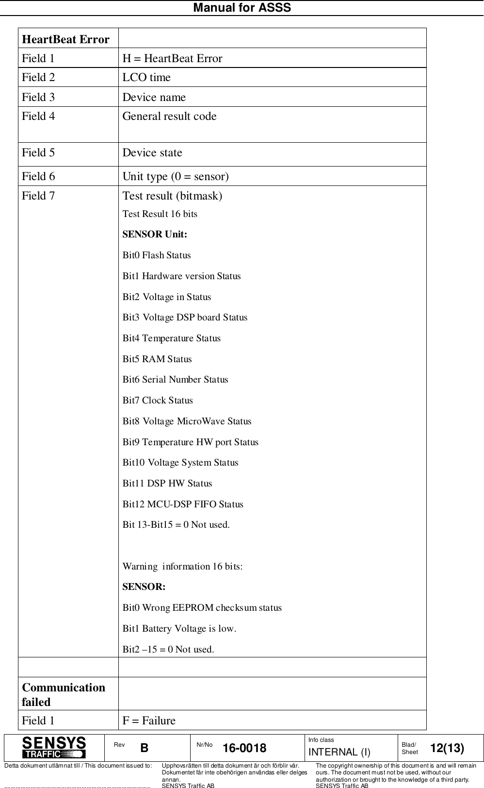
![Manual for ASSSRev B Nr/No 16-0018 Info classINTERNAL (I) Blad/Sheet 13(13)Detta dokument utlämnat till / This document issued to:.......................................................................................Upphovsrätten till detta dokument är och förblir vår.Dokumentet får inte obehörigen användas eller delgesannan.SENSYS Traffic ABThe copyright ownership of this document is and will remainours. The document must not be used, without ourauthorization or brought to the knowledge of a third party.SENSYS Traffic ABField 2 LCO timeField 3 Device nameField 4 ”Communication lost”Communicationre-establishedField 1 I = InformationField 2 LCO timeField 3 Device nameField 4 ”Communication re-established”Ordered ResetField 1 O = Ordered resetField 2 LCO timeField 3 Device nameField 4 Reset type Table 1The LCO application handles log files as well as the log window. The directory where the logfiles are stored is configured in the ”Options | Preferences…” dialog. It is currently set to”C:\LCO_logfiles”. The log file names are constructed as follows:<site code>_<LCO date>_<LCO time>.logwhere LCO date is formatted as YYYYMMDD and LCO time is formatted as HHMMSS. Thefile begins with a chunk of header information and ends with the time when the file wascompleted. In between these blocks message and system logs are stored. The messageinformation is in most cases stored as a hexadecimal dump of the raw binary message data.9 APPENDIXAppendix No. Name[App 1] None9.1 Appendix 1.None.](https://usermanual.wiki/Sensys-Traffic/RS240/User-Guide-126163-Page-13.png)