Sensys Traffic RS240 Traffic Sensor User Manual Operation manual
Sensys Traffic AB Traffic Sensor Operation manual
Operation manual

Ritad/
Drawn 2000-01-14 SVNI Objekt/
Project Infoklass / Info class
Gransk/
Check 2000-01-14 STST Ingår i/
Next assy Internal (I)
Prod/
Prod Lagr/
File 126163
Prov/
Proto Ben/
Name
Serie/
Series
B - 0002
Bet/Rev ÄO-nr/ECO No W Nr/No 16-0018 Blad/
Sheet 1(13)
Detta dokument utlämnat till / This document issued to:
.......................................................................................
Upphovsrätten till detta dokument är och förblir vår.
Dokumentet får inte obehörigen användas eller delges
annan.
SENSYS Traffic AB
The copyright ownership of this document is and will remain ours.
The document must not be used, without our authorization or
brought to the knowledge of a third party.
SENSYS Traffic AB
Manual
for
Automatic Speed Safety System
With
SENSYS 240

Manual for ASSS
Rev B Nr/No 16-0018 Info class
INTERNAL (I) Blad/
Sheet 2(13)
Detta dokument utlämnat till / This document issued to:
.......................................................................................
Upphovsrätten till detta dokument är och förblir vår.
Dokumentet får inte obehörigen användas eller delges
annan.
SENSYS Traffic AB
The copyright ownership of this document is and will remain
ours. The document must not be used, without our
authorization or brought to the knowledge of a third party.
SENSYS Traffic AB
DISCLAIMER
The information in this document is subject to change without notice and does not represent a
commitment on any part by SENSYS Traffic AB.
In no event shall SENSYS Traffic AB or its authors of this document be liable for special, direct,
indirect, or consequential damage, costs, losses, charges, demands, claims, claims for lost profits,
fees, or expenses of any nature or kind.
COPYRIGHT
The copyright ownership of this document is and will remain ours. The document must not be
used, without our authorisation or brought to the knowledge of a third party.
TRADEMARKS
Windows and MS-DOS are trademarks of Microsoft Corp.
All other product names are trademarks or registered trademarks of their respective owners.
REVISION SUMMARY
Updates will be issued when needed and noted on this page in the following issues of this
document.
Rev Date Issued by Description
A 2000-01-14 SVNI First edition.
B 2000-01-26 SVNI Chapter 8 LCO operation and chapter 8.1 Calibration have been updated.

Manual for ASSS
Rev B Nr/No 16-0018 Info class
INTERNAL (I) Blad/
Sheet 3(13)
Detta dokument utlämnat till / This document issued to:
.......................................................................................
Upphovsrätten till detta dokument är och förblir vår.
Dokumentet får inte obehörigen användas eller delges
annan.
SENSYS Traffic AB
The copyright ownership of this document is and will remain
ours. The document must not be used, without our
authorization or brought to the knowledge of a third party.
SENSYS Traffic AB
Table of Contents
1 SCOPE ..........................................................................................................................................................4
1.1 IDENTIFICATION ........................................................................................................................................4
1.2 INTRODUCTION..........................................................................................................................................4
2 REFERENCED DOCUMENTS.................................................................................................................4
3 DEFINITIONS, ACRONYMS AND ABBREVIATIONS........................................................................4
4 EQUIPMENT...............................................................................................................................................5
5 CONNNECTION .........................................................................................................................................5
5.1 SENSYS 240 ............................................................................................................................................5
6 SYSTEM OPERATION..............................................................................................................................6
7 SENSYS 240 OPERATION ........................................................................................................................6
7.1 SENSOR START-UP .....................................................................................................................................6
7.2 CONTINUOS SENSOR TEST .........................................................................................................................7
8 LCO OPERATION......................................................................................................................................7
8.1 CALIBRATION............................................................................................................................................8
8.2 RESETTING THE SENSOR..........................................................................................................................10
8.3 LOGS .......................................................................................................................................................11
8.3.1 Log window format..............................................................................................................................11
CalibrationCfm...............................................................................................................................................11
HeartBeat Error ..............................................................................................................................................12
Ordered Reset.................................................................................................................................................13
9 APPENDIX.................................................................................................................................................13
9.1 APPENDIX 1.............................................................................................................................................13

Manual for ASSS
Rev B Nr/No 16-0018 Info class
INTERNAL (I) Blad/
Sheet 4(13)
Detta dokument utlämnat till / This document issued to:
.......................................................................................
Upphovsrätten till detta dokument är och förblir vår.
Dokumentet får inte obehörigen användas eller delges
annan.
SENSYS Traffic AB
The copyright ownership of this document is and will remain
ours. The document must not be used, without our
authorization or brought to the knowledge of a third party.
SENSYS Traffic AB
1 SCOPE
1.1 Identification
Product Nr. Name
10-0008 SENSYS 240
1.2 Introduction
This document defines how the sensor SENSYS 240 will be used.
2 REFERENCED DOCUMENTS
No. Identification Issue Name or Description
[Ref A] 16-0019 A Requirement Specification for Automatic Speed
Safety System
3 DEFINITIONS, ACRONYMS AND ABBREVIATIONS
Definition,
Acronym or
Abbreviation
Explanation
ASSS Automatic Speed Safety System
LCO Link Controller Operator
MCU Micro Controller Unit
SENSYS 240 Sensor for 24 GHz, CAN interface.
Manual for ASSS
Rev B Nr/No 16-0018 Info class
INTERNAL (I) Blad/
Sheet 5(13)
Detta dokument utlämnat till / This document issued to:
.......................................................................................
Upphovsrätten till detta dokument är och förblir vår.
Dokumentet får inte obehörigen användas eller delges
annan.
SENSYS Traffic AB
The copyright ownership of this document is and will remain
ours. The document must not be used, without our
authorization or brought to the knowledge of a third party.
SENSYS Traffic AB
4 EQUIPMENT
The system has the following equipments:
• SENSYS 240
• Combined Power and CAN Cabling
• Link Controller Operator (LCO)
• Power supply to the SENSYS 240 is 10.8 – 16.3 V DC and 1.3 Ampere.
• Power supply to the LCO is 12V DC and 2.5 Ampere.
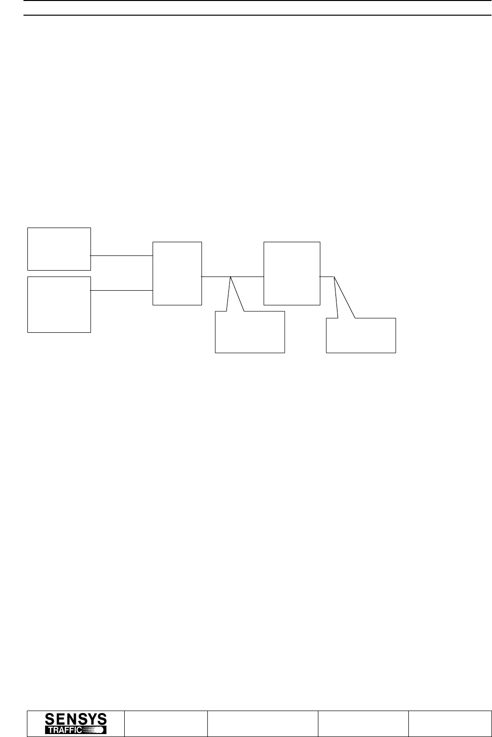
5 CONNNECTION
The picture above shows how the different equipments are physical connected.
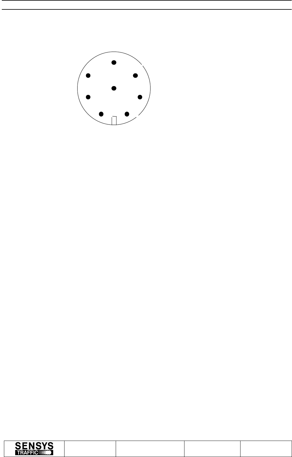
5.1 SENSYS 240
The SENSYS 240 has two connectors. Both Connectors have CAN and Power supply interface.
The below defines the pinout for each SENSYS 240 connector:
Pin number:
1. Power Supply. (+12V.)
2. CAN low signal.
3. Ground, Power Supply.
4. Power Supply. (+12V.)
5. Ground, Power Supply.
8. CAN High signal.
LCO
Power
Supply to
LCO
Power
Supply to
SENSYS 240
SENSYS
240
CAN and power
supply cabling Terminate
Connector
Manual for ASSS
Rev B Nr/No 16-0018 Info class
INTERNAL (I) Blad/
Sheet 6(13)
Detta dokument utlämnat till / This document issued to:
.......................................................................................
Upphovsrätten till detta dokument är och förblir vår.
Dokumentet får inte obehörigen användas eller delges
annan.
SENSYS Traffic AB
The copyright ownership of this document is and will remain
ours. The document must not be used, without our
authorization or brought to the knowledge of a third party.
SENSYS Traffic AB
Note. Each SENSYS 240 Connector must be connected to Power and CAN Cabling or a
terminate connector.
6 SYSTEM OPERATION
The below defines the system operations:
The LCO will continuously verify that the sensor works. This will be done with a Heartbeat
message which will be transmitted to the sensor each 10 seconds interval.
Information of sensor problem will be stored in the log file and on the LCO data screen.
The sensor will also perform a calibration, if the internally sensor temperature increases over the
accepted level. The sensor will then report to the LCO about the calibration result. After
calibration the sensor will go in standby mode, if the temperature is still high.
The sensor will also perform a calibration, if the internally system voltage decreases to a not
accepted level. The sensor will then report to the LCO about the calibration result. After
calibration the sensor will go in standby mode, if the internally voltage is still low.
The LCO can also perform an ordered sensor calibration. The sensor then performs a calibration
and reports the result to the LCO.
7 SENSYS 240 OPERATION
7.1 Sensor start-up
After power on the sensor start with red LED indication.
The sensor will then start with start-up tests.
The start-up will verify the following:
1. The MCU Flash memory and SW checksum.
2. The MCU RAM memory.
2
4
8
1
6
5
7
3

Manual for ASSS
Rev B Nr/No 16-0018 Info class
INTERNAL (I) Blad/
Sheet 7(13)
Detta dokument utlämnat till / This document issued to:
.......................................................................................
Upphovsrätten till detta dokument är och förblir vår.
Dokumentet får inte obehörigen användas eller delges
annan.
SENSYS Traffic AB
The copyright ownership of this document is and will remain
ours. The document must not be used, without our
authorization or brought to the knowledge of a third party.
SENSYS Traffic AB
3. That the hardware version is accepted.
4. That the internal serial number HW works.
5. That the internal real time clock works.
6. That the in voltage is accepted to the sensor.
7. That the internal voltage is accepted to the DSP board.
8. That the internal voltage is accepted to the MicroWave unit.
9. That the internal temperature is accepted.
10. That the internal system voltage is accepted.
11. That the internal DSP HW works.
12. That the internal MCU-DSP FIFO works.
If the above start-up test passing, then the sensor application will start and the LED will change
colour to green. Otherwise the application will not start and the LED will still be red.
If the above start-up test failed a Reset command from LCO is necessary to perform a new start-
up test (not enough with a power off/on sequence).
The start-up test will also verify the following warning tests:
1. The internal EEPROM checksum.
2. That the internal backup voltage is accepted.
The result of the warning test will be reported to the LCO via the Heartbeat message.
7.2 Continuos Sensor test
The Sensor will continuos verify the following:
1. That the internal temperature is accepted.
2. That the internal system voltage is accepted.
If any of the above tests fails, the sensor will automatically perform a calibration and report the
result to the LCO. After that and if the alarm is still activated the sensor will turn off.
If the sensor has turned off and the alarm has been released the sensor will restart again
according to the Sensor start-up chapter above.
8 LCO OPERATION
Make sure that the files LCO.EXE, LCO.DAT and LCO.STP are located in the same directory.
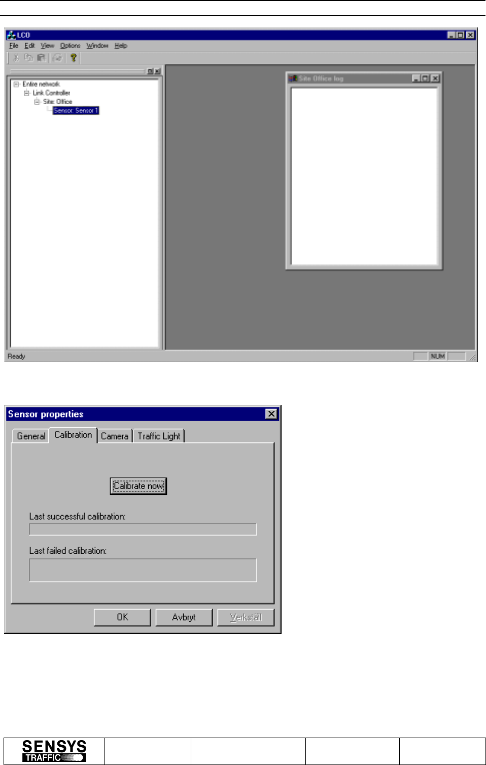
Start the application by double-clicking LCO.EXE. A window similar to the one in Figure 1 will

Manual for ASSS
Rev B Nr/No 16-0018 Info class
INTERNAL (I) Blad/
Sheet 8(13)
Detta dokument utlämnat till / This document issued to:
.......................................................................................
Upphovsrätten till detta dokument är och förblir vår.
Dokumentet får inte obehörigen användas eller delges
annan.
SENSYS Traffic AB
The copyright ownership of this document is and will remain
ours. The document must not be used, without our
authorization or brought to the knowledge of a third party.
SENSYS Traffic AB
appear. The tree view to the left contains all the devices that the application is responsible for.
The two first levels are currently unchangeable, whereas Sites, Sensors, Cameras and Traffic
Lights are possible to add, configure and delete. One site (Office) containing one sensor (Sensor
1) is defined in the delivered set-up files, in accordance with Figure 1.
The application does not send anything to any device until a measurement is started by right-
clicking on a site and selecting “Start Measurement…”. If that is done, LCO will try to connect
to the devices in the site and then start sending heartbeat requests to them every 10 seconds.
8.1 Calibration
Calibration requests are sent to every sensor in a measuring site with the periodicity supplied in
the ”Options | Preferences…” dialog. In order to manually request the sensor to perform a
calibration the following steps should be performed:
1. Select the site in the tree view and click the right mouse button. A pop-up menu appears.
2. Select “Start measurement..”, supply user names in the “Start measurement” dialog and press
“OK”. A log window appears.
3. Select the sensor in the tree view and click the right mouse button. A pop-up menu appears.
4. Select Properties… from the pop-up menu. The “Sensor Properties” dialog appears.
5. Select the Calibration tab. The dialog should look as in Figure 2.
6. Press the Calibrate button.
Manual for ASSS
Rev B Nr/No 16-0018 Info class
INTERNAL (I) Blad/
Sheet 9(13)
Detta dokument utlämnat till / This document issued to:
.......................................................................................
Upphovsrätten till detta dokument är och förblir vår.
Dokumentet får inte obehörigen användas eller delges
annan.
SENSYS Traffic AB
The copyright ownership of this document is and will remain
ours. The document must not be used, without our
authorization or brought to the knowledge of a third party.
SENSYS Traffic AB
Figure 1
Figure 2
Manual for ASSS
Rev B Nr/No 16-0018 Info class
INTERNAL (I) Blad/
Sheet 10(13)
Detta dokument utlämnat till / This document issued to:
.......................................................................................
Upphovsrätten till detta dokument är och förblir vår.
Dokumentet får inte obehörigen användas eller delges
annan.
SENSYS Traffic AB
The copyright ownership of this document is and will remain
ours. The document must not be used, without our
authorization or brought to the knowledge of a third party.
SENSYS Traffic AB
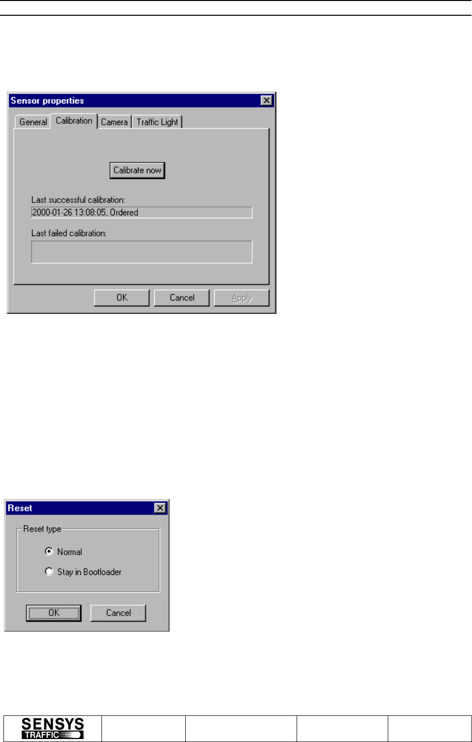
If the sensor responds, the response will be logged in the log window as well as in the log file.
The dialog tab will also indicate the parameters of the last received successful and failed
calibrations. Figure 3 shows a dialog where this information is included.
Figure 3
8.2 Resetting the sensor
In order to reset the sensor the following steps should be performed:
1. Select the sensor in the tree view and click the right mouse button. A pop-up menu appears.
2. Select Reset… from the pop-up menu. The “Reset” dialog appears as shown in Figure 4.
3. Choose the appropriate type of reset, here always the normal reset and then select OK.
Figur 6
Manual for ASSS
Rev B Nr/No 16-0018 Info class
INTERNAL (I) Blad/
Sheet 11(13)
Detta dokument utlämnat till / This document issued to:
.......................................................................................
Upphovsrätten till detta dokument är och förblir vår.
Dokumentet får inte obehörigen användas eller delges
annan.
SENSYS Traffic AB
The copyright ownership of this document is and will remain
ours. The document must not be used, without our
authorization or brought to the knowledge of a third party.
SENSYS Traffic AB
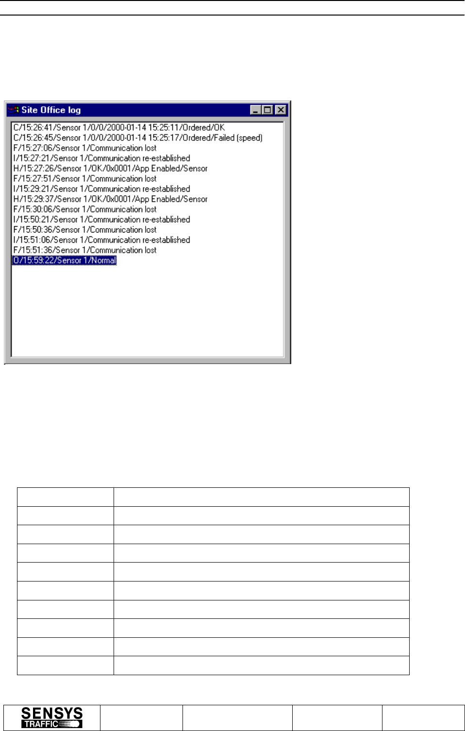
8.3 Logs
The log window shows information about certain events for the site. Figure 5 shows some
possible logs.
8.3.1 Log window format
Below defines the different window log messages.
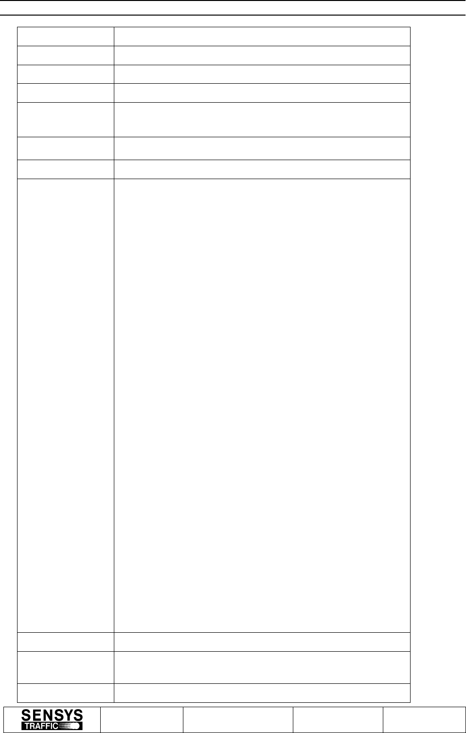
CalibrationCfm
Field 1 C = Calibration Confirm
Field 2 LCO time
Field 3 Sensor name
Field 4 Sensor number
Field 5 General result code
Field 6 Sensor time
Field 7 Calibration reason
Field 8 Calibration result
Figure 7
Manual for ASSS
Rev B Nr/No 16-0018 Info class
INTERNAL (I) Blad/
Sheet 12(13)
Detta dokument utlämnat till / This document issued to:
.......................................................................................
Upphovsrätten till detta dokument är och förblir vår.
Dokumentet får inte obehörigen användas eller delges
annan.
SENSYS Traffic AB
The copyright ownership of this document is and will remain
ours. The document must not be used, without our
authorization or brought to the knowledge of a third party.
SENSYS Traffic AB
HeartBeat Error
Field 1 H = HeartBeat Error
Field 2 LCO time
Field 3 Device name
Field 4 General result code
Field 5 Device state
Field 6 Unit type (0 = sensor)
Field 7 Test result (bitmask)
Test Result 16 bits
SENSOR Unit:
Bit0 Flash Status
Bit1 Hardware version Status
Bit2 Voltage in Status
Bit3 Voltage DSP board Status
Bit4 Temperature Status
Bit5 RAM Status
Bit6 Serial Number Status
Bit7 Clock Status
Bit8 Voltage MicroWave Status
Bit9 Temperature HW port Status
Bit10 Voltage System Status
Bit11 DSP HW Status
Bit12 MCU-DSP FIFO Status
Bit 13-Bit15 = 0 Not used.
Warning information 16 bits:
SENSOR:
Bit0 Wrong EEPROM checksum status
Bit1 Battery Voltage is low.
Bit2 –15 = 0 Not used.
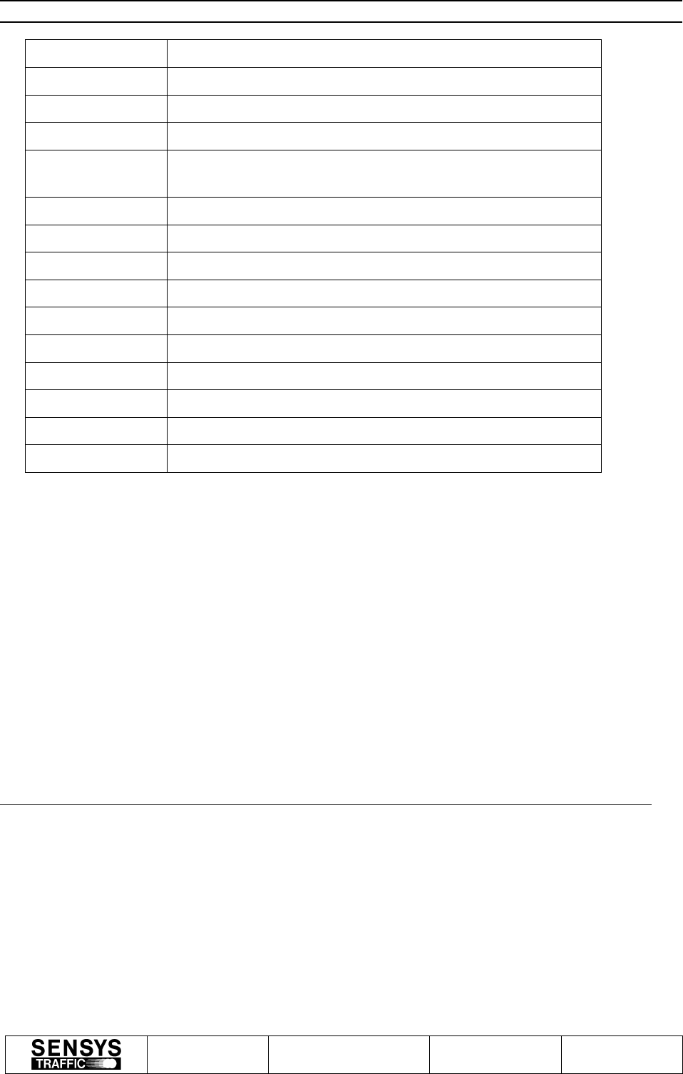
Communication
failed
Field 1 F = Failure
Manual for ASSS
Rev B Nr/No 16-0018 Info class
INTERNAL (I) Blad/
Sheet 13(13)
Detta dokument utlämnat till / This document issued to:
.......................................................................................
Upphovsrätten till detta dokument är och förblir vår.
Dokumentet får inte obehörigen användas eller delges
annan.
SENSYS Traffic AB
The copyright ownership of this document is and will remain
ours. The document must not be used, without our
authorization or brought to the knowledge of a third party.
SENSYS Traffic AB
Field 2 LCO time
Field 3 Device name
Field 4 ”Communication lost”
Communication
re-established
Field 1 I = Information
Field 2 LCO time
Field 3 Device name
Field 4 ”Communication re-established”
Ordered Reset
Field 1 O = Ordered reset
Field 2 LCO time
Field 3 Device name
Field 4 Reset type
Table 1
The LCO application handles log files as well as the log window. The directory where the log
files are stored is configured in the ”Options | Preferences…” dialog. It is currently set to
”C:\LCO_logfiles”. The log file names are constructed as follows:
<site code>_<LCO date>_<LCO time>.log
where LCO date is formatted as YYYYMMDD and LCO time is formatted as HHMMSS. The
file begins with a chunk of header information and ends with the time when the file was
completed. In between these blocks message and system logs are stored. The message
information is in most cases stored as a hexadecimal dump of the raw binary message data.
9 APPENDIX
Appendix No. Name
[App 1] None
9.1 Appendix 1.
None.