Sentilla TMOTESKY Tmote Sky User Manual tmote sky datasheet 102
Sentilla Corporation Tmote Sky tmote sky datasheet 102
UserManual.wiki
>
Sentilla
>
TMOTESKY User Manual
Users Manual Revised
Navigation menu
Upload a User Manual
Namespaces
Wiki Guide
HTML
PDF
Info
Views
User Manual
Discussion / Help
Navigation
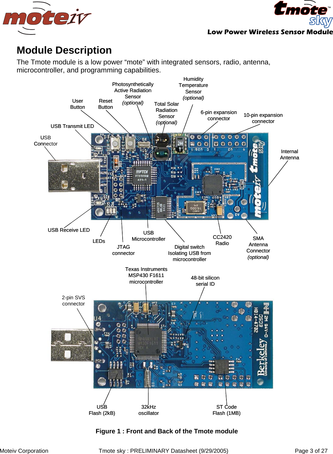
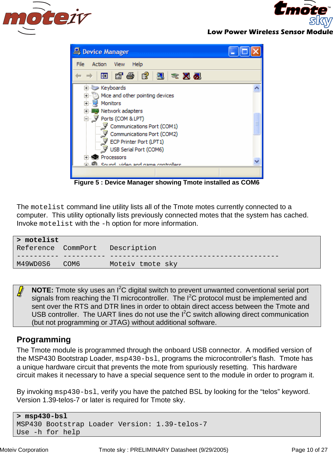
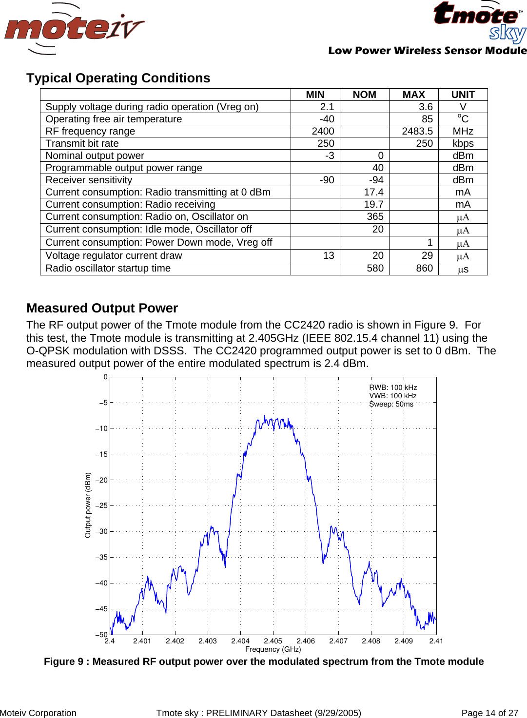
![Low Power Wireless Sensor Module Moteiv Corporation Tmote sky : PRELIMINARY Datasheet (9/29/2005) Page 13 of 27 Radio Description Tmote features the Chipcon CC2420 radio for wireless communications. The CC2420 is an IEEE 802.15.4 compliant radio providing the PHY and some MAC functions. With sensitivity exceeding the IEEE 802.15.4 specification and low power operation, the CC2420 provides reliable wireless communication. The CC2420 is highly configurable for many applications with the default radio settings providing IEEE 802.15.4 compliance. Features and usage of the CC2420 is available in Chipcon’s datasheet at http://www.chipcon.com The CC2420 is controlled by the TI MSP430 microcontroller through the SPI port and a series of digital I/O lines and interrupts (see the Schematics on page 7 for more information). The radio may be shut off by the microcontroller for low power duty cycled operation. The CC2420 has programmable output power. Common CC2420 register values and their corresponding current consumption and output power are shown in Figure 7. PA_LEVEL TXCTRL register Output Power [dBm] Current Consumption [mA] 31 0xA0FF 0 17.4 27 0xA0FB -1 16.5 23 0xA0F7 -3 15.2 19 0xA0F3 -5 13.9 15 0xA0EF -7 12.5 11 0xA0EB -10 11.2 7 0xA0E7 -15 9.9 3 0xA0E3 -25 8.5 Figure 7 : Output power configuration for the CC2420 The CC2420 provides a digital received signal strength indicator (RSSI) that may be read any time. Additionally, on each packet reception, the CC2420 samples the first eight chips, calculates the error rate, and produces a link quality indication (LQI) value with each received packet. A mapping from RSSI to the RF level in dBm is shown in Figure 8. Figure 8 : Received Signal Strength Indicator mapping to RF Power [dBm]](https://usermanual.wiki/Sentilla/TMOTESKY/User-Guide-613136-Page-10.png)
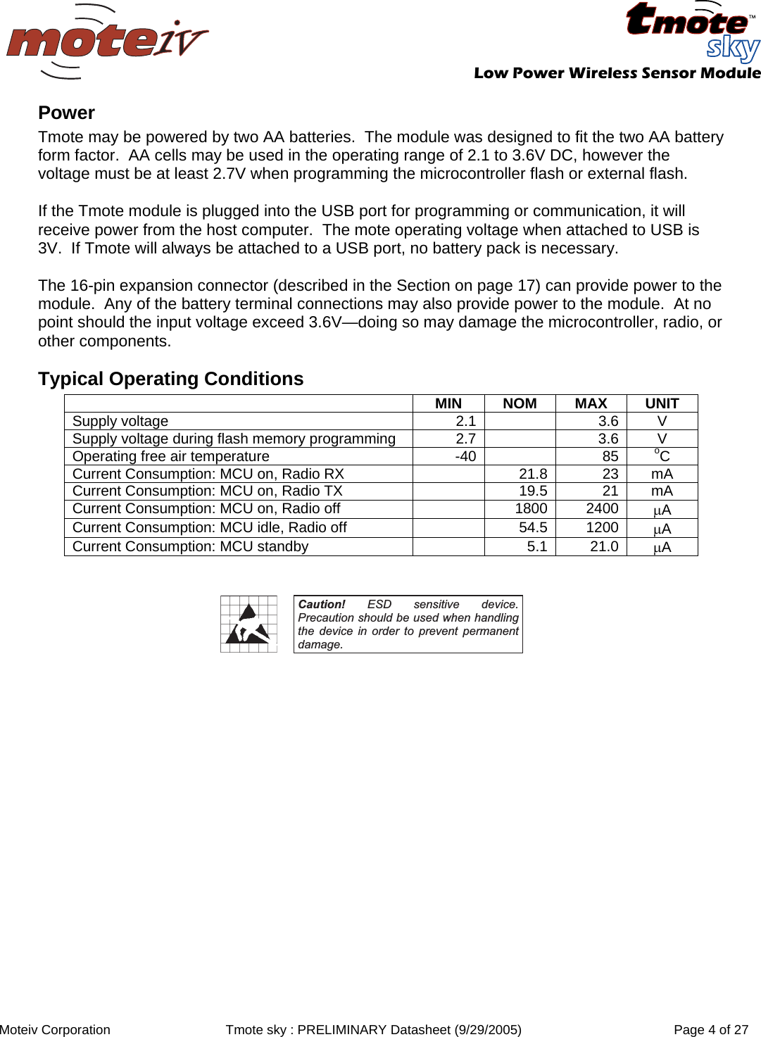
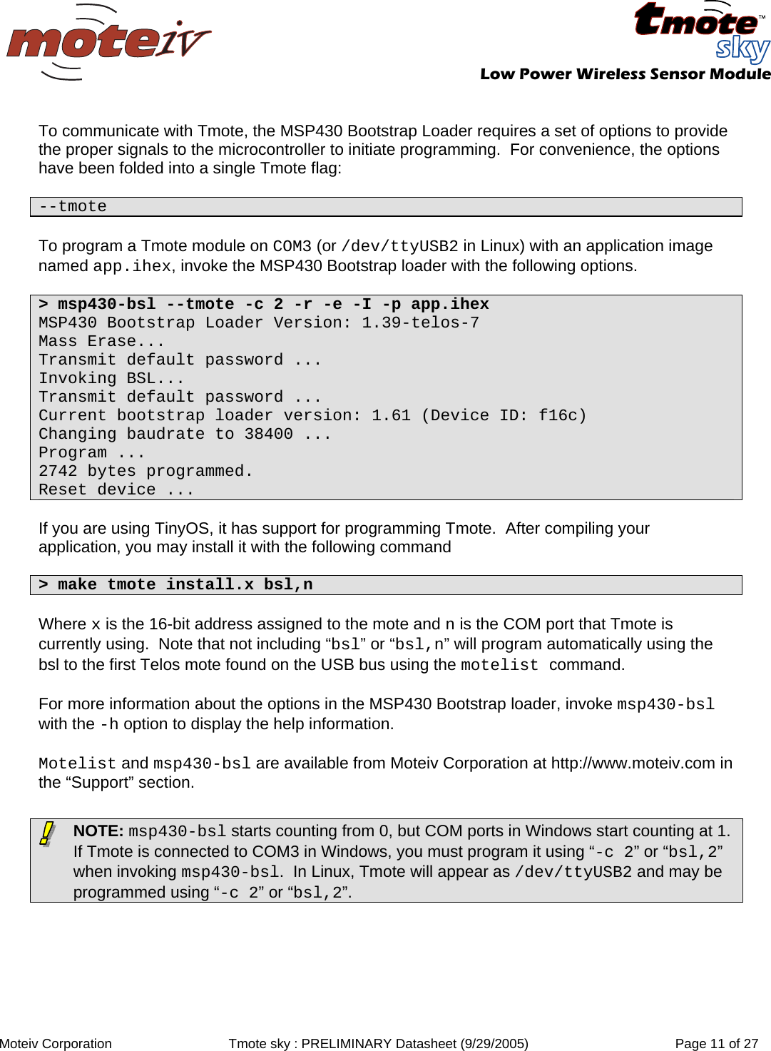
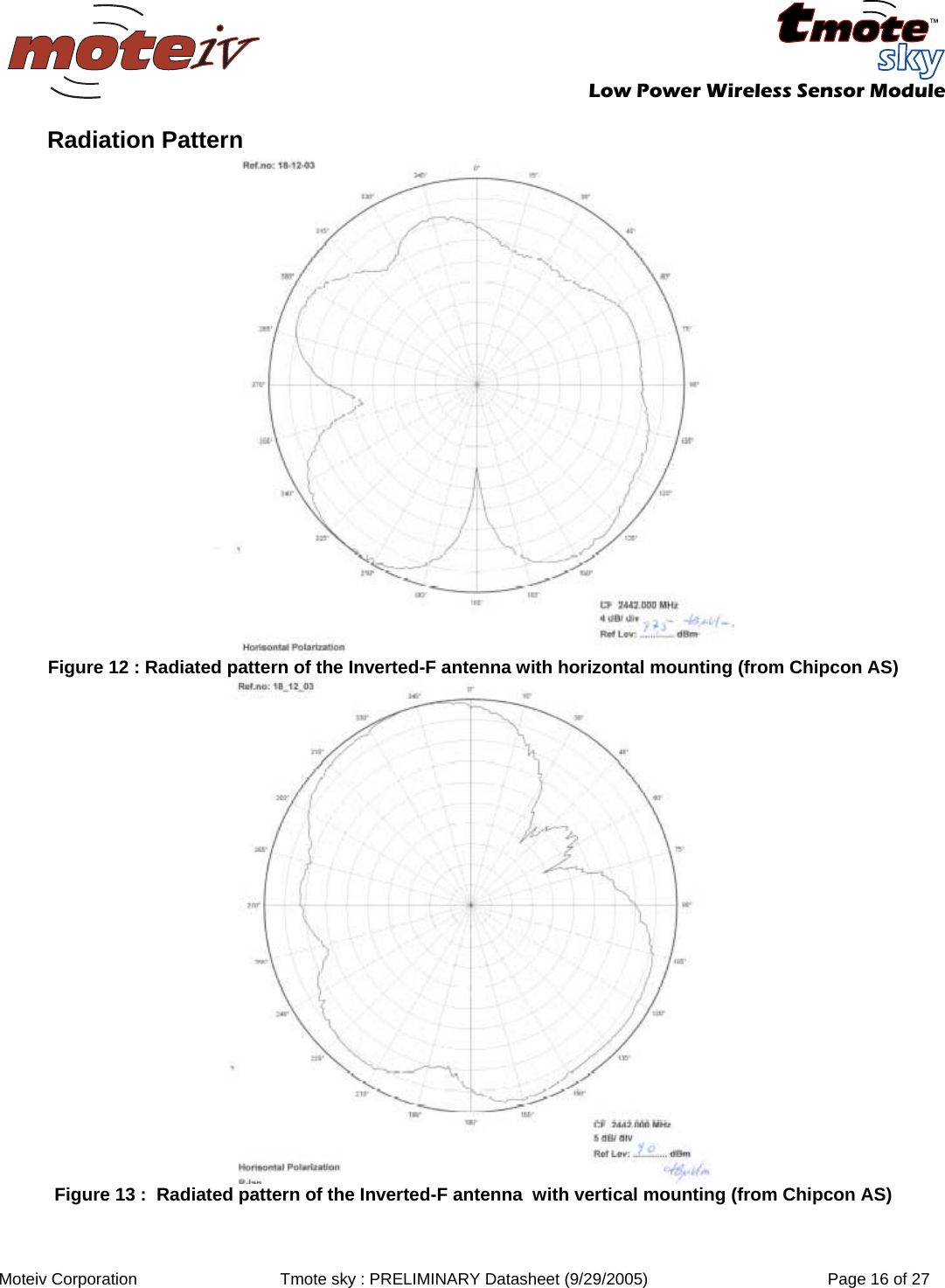
![Low Power Wireless Sensor Module Moteiv Corporation Tmote sky : PRELIMINARY Datasheet (9/29/2005) Page 15 of 27 Antenna Tmote’ internal antenna is an Inverted-F microstrip design protruding from the end of the board away from the battery pack. The Inverted-F antenna is a wire monopole where the top section is folded down to be parallel with the ground plane. Although not a perfect omnidirectional pattern, the antenna may attain 50-meter range indoors and upwards of 125-meter range outdoors. Measurements of the internal antenna’s performance with and without a battery pack are show in Figure 10 and Figure 11. Approximate radiation patterns for the Inverted-F antenna as provided by Chipcon AS are shown in Figure 12 and Figure 13. Internal Antenna without Battery Pack 2004/11/25 Thr 14:44:06CH2 S11 SMITH(R+jX) FS 1.000MKR 3: 2.483 958 333GHz65.166 4.083 Cor3:2.483 958GHz 65.041 4.227 270.843pH2:2.450 000GHz 39.757 -4.623 14.050pF1:2.400 000GHz 40.014 -40.598 1.633pF312START 2.3GHz [ 10.00 dBm] STOP 2.55GHz2.3 2.325 2.35 2.375 2.4 2.425 2.45 2.475 2.5 2.525 2.55−50−45−40−35−30−25−20−15−10−50Frequency (GHz)Log(|S11|) (dB)12341: 2.400 GHz −7.40 dB2: 2.450 GHz −16.58 dB3: 2.485 GHz −16.58 dB4: 2.500 GHz −12.50 dB Figure 10 : S11 measurements for the internal inverted-F antenna when no battery pack is present Internal Antenna with Battery Pack 2004/11/25 Thr 14:49:13CH2 S11 SMITH(R+jX) FS 1.000MKR 3: 2.483 958 333GHz57.265 7.168 Cor3:2.483 958GHz 57.205 7.146 457.900pH2:2.450 000GHz 34.763 -8.204 7.917pF1:2.400 000GHz 38.610 -49.225 1.347pF123START 2.3GHz [ 10.00 dBm] STOP 2.55GHz2.3 2.325 2.35 2.375 2.4 2.425 2.45 2.475 2.5 2.525 2.55−50−45−40−35−30−25−20−15−10−50Frequency (GHz)Log(|S11|) (dB)12341: 2.400 GHz −5.10 dB2: 2.450 GHz −13.27 dB3: 2.485 GHz −20.92 dB4: 2.500 GHz −12.24 dB Figure 11 : S11 measurements for the internal inverted-F antenna with battery pack underneath](https://usermanual.wiki/Sentilla/TMOTESKY/User-Guide-613136-Page-12.png)
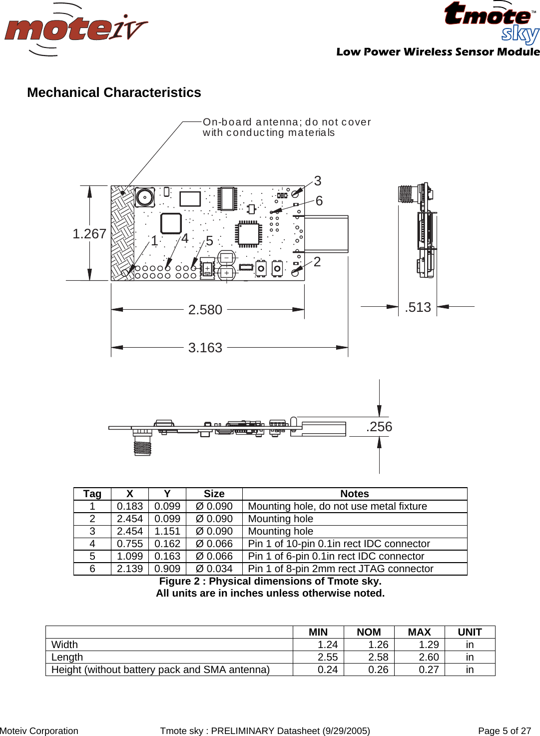
![Low Power Wireless Sensor Module Moteiv Corporation Tmote sky : PRELIMINARY Datasheet (9/29/2005) Page 24 of 27 Agency Certification FCC Certification The Tmote sky module complies with Part 15 of the FCC rules and regulations. Compliance with the labeling requirements, FCC notices and antenna usage guidelines is required. To fulfill FCC Certification requirements, the OEM must comply with the following regulations: 1. The system integrator must ensure that the text on the external label provided with this device is placed on the outside of the final product [Figure 26]. 2. The Tmote sky module may be used only with approved antennas that have been tested with this module. OEM Labeling requirement Contains FCC ID: TOQTMOTESKY The enclosed device complies with Part 15 of the FCC Rules. Operation is subject to the following two conditions: (1) this device may not cause harmful interference and (2) this device must accept any interference received, including interference that may cause undesired operation Figure 26: Required FCC label for OEM products containing the Tmote sky module. FCC Notices WARNING: The Original Equipment Manufacturer (OEM) must ensure that FCC labeling requirements are met. This includes a clearly visible label on the outside of the final product enclosure that displays the contents shown in the figure below. IMPORTANT: The Tmote sky module has been certified by the FCC for use with other products without any further certification (as per FCC section 2.1091). Changes or modifications not expressly approved by Moteiv Corporation could void the user's authority to operate the equipment. IMPORTANT: OEMs must test final product to comply with unintentional radiators (FCC section 15.107 & 15.109) before declaring compliance of their final product to Part 15 of the FCC Rules. IMPORTANT: The RF module has been certified for remote and base radio applications. If the module will be used for portable applications, the device must undergo SAR testing. This equipment has been tested and found to comply with the limits for a Class B digital device, pursuant to Part 15 of the FCC Rules. These limits are designed to provide reasonable protection against harmful interference in a residential installation. This equipment generates, uses and can radiate radio frequency energy and, if not installed and used in accordance with the instructions, may cause harmful interference to radio communications. However, there is no guarantee that interference will not occur in a particular installation. If this equipment does cause harmful interference to radio or television reception, which can be determined by turning the equipment off and on, the user is encouraged to try to correct the interference by one or more of the following measures: Re-orient or relocate the receiving antenna, Increase the separation between the equipment and receiver, Connect equipment and receiver to outlets on different circuits, or Consult the dealer or an experienced radio/TV technician for help.](https://usermanual.wiki/Sentilla/TMOTESKY/User-Guide-613136-Page-21.png)