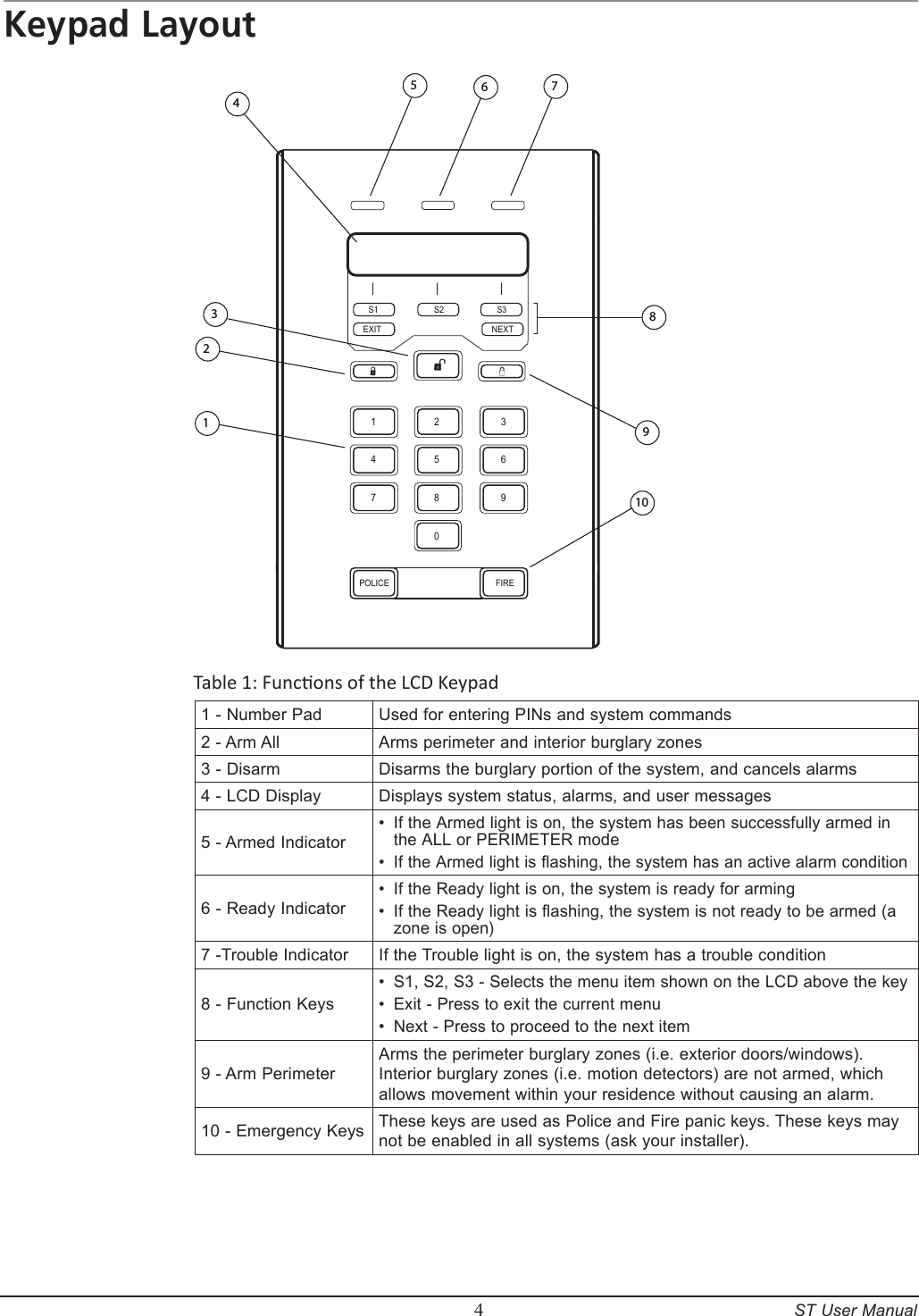
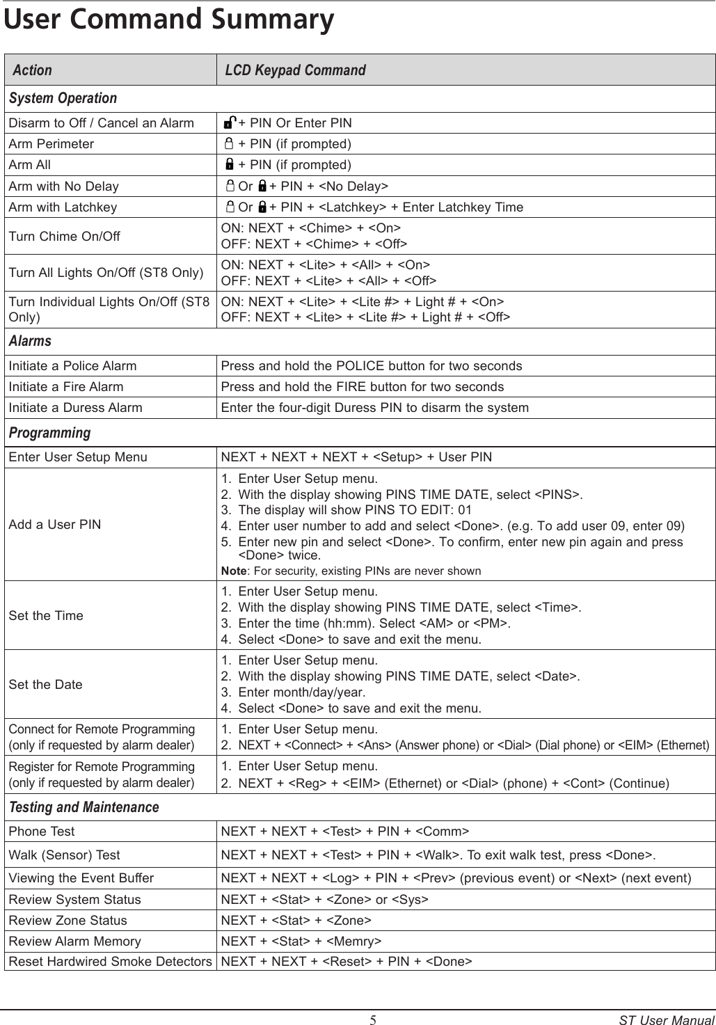
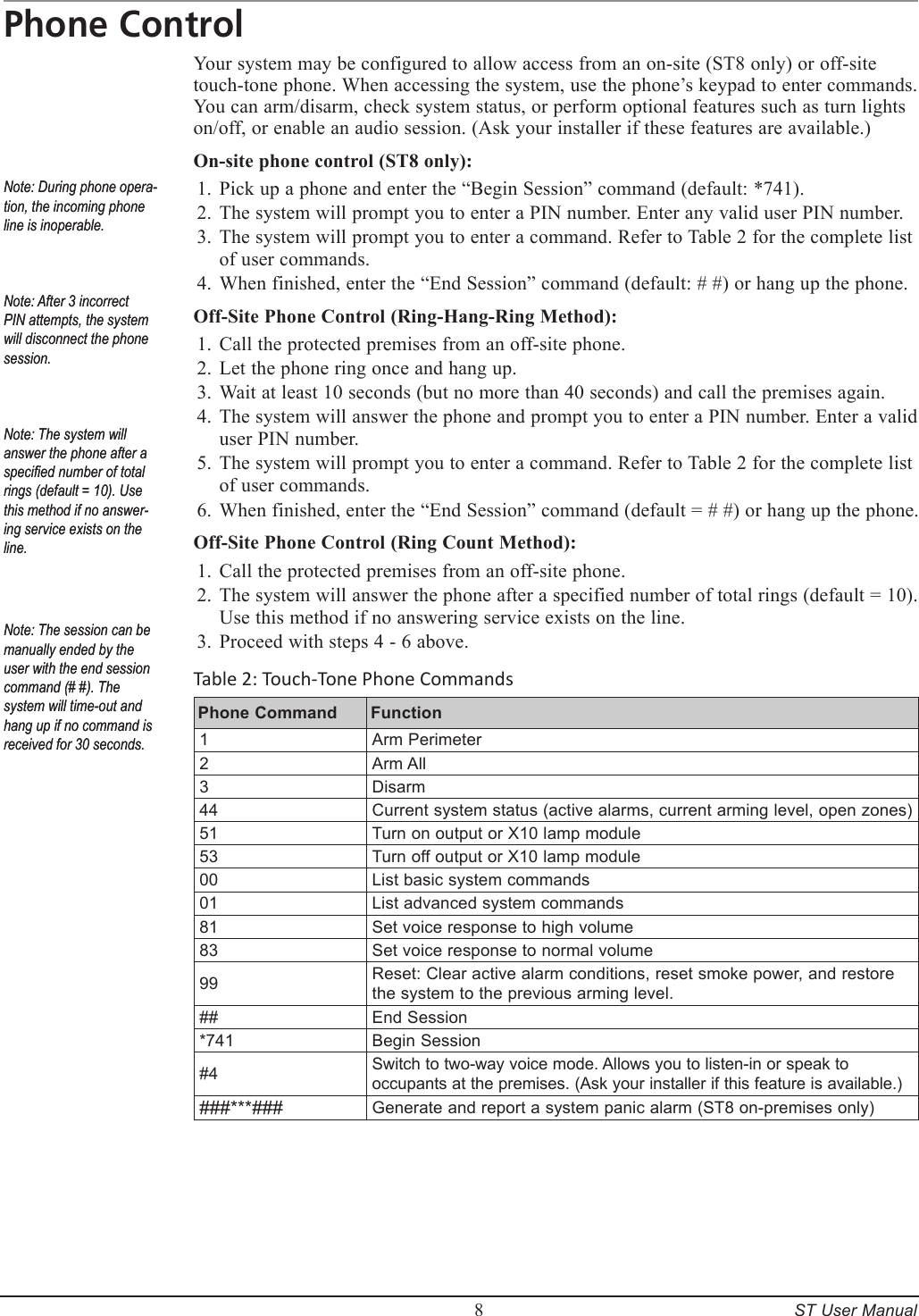
Sequel Technologies STEX01 Control, ST Express User Manual CERTIFICATE OF COMPLIANCE

Sequel Technologies, LLC Control, ST Express CERTIFICATE OF COMPLIANCE

User Manual

Rhein Tech Laboratories, Inc.  Client:  Sequel Technologies, LLC 360 Herndon Parkway    Model:  STCP-STE Suite 1400  Standard: FCC 15.231                                             FCC ID:  V4X-STEX01 Herndon, VA 20170 http://www.rheintech.com Report #: 2008068    Page 26 of 39       Appendix G:  Manual  Please see the following pages.
ST Express / ST8 Security SystemsDocument Number: 550-00008 Rev. AUser ManualCopyright 2008Sequel Technologies, LLC.
iiContentsSystem Overview ............................................. 3Control Panel .............................................. 3Keypads................................................. 3Zones/Sensors ............................................. 3Modules................................................. 3Keypad Layout ............................................... 4User Command Summary ........................................ 5Arming the System ............................................ 6Arming the Perimeter ......................................... 6Arming All ............................................... 6No Delay ................................................ 6Latchkey Feature ............................................ 6Bypassing Sensors ........................................... 6Disarming the System........................................... 7Wireless Keyfob Operation ....................................... 7Phone Control................................................ 8Entry and Exit Delay ........................................... 9Chime Mode................................................. 9X10 Lights .................................................. 9Checking the Status ............................................10Email Notification .............................................10Alarm Conditions .............................................11Fire Alarms ...............................................11Police Alarms..............................................11Activating a Panic Alarm from an LCD Keypad ...........................11Activating Alarms from your Wireless Keyfob ............................11Duress Alarm ..............................................11Siren Time-out .............................................11Dialer Delay ..............................................12System Alarm Responses........................................12User Setup Mode..............................................13Entering User Setup Mode .......................................13User PINs................................................13Setting the Time and Date .......................................14Connecting to the Remote Service Tool (RST) ............................14Testing the System.............................................15Test Command Summary .......................................15Walk Test ................................................15Dialer Test ...............................................16Wireless Sensor Batteries .......................................16Trouble Conditions ............................................17Silencing Trouble Beeps ........................................17
        3     ST User ManualSystem OverviewCongratulations on your ownership of an ST security system, which offers the latest in secu-rity protection technology. The ST system consists of a control panel, at least one keypad and various sensors that provide burglary and/or fire protection. In addition, your system may be programmed to send alarm and status messages to a central alarm monitoring station.Control PanelThe control panel is the main processing unit for all system functions. It receives and responds to signals from sensors throughout the premises. For monitored systems, the control panel con-nects to the premises phone line or an optional Ethernet module for central station reporting.KeypadsLCD KeypadThe 2-line x 16 character LCD keypad allows control and programming of the security system and displays system status messages.Wireless KeyfobThe wireless keyfob allows users the ability to arm and disarm the system, turn lights on/off (if programmed), and activate a panic alarm. The keyfob includes a 5 year user-replaceable battery.Zones/SensorsThe system includes various detection devices, which are identified by the security system as zones. Each zone has a type of detection sensor, which is installed throughout the prem-ises to identify alarm conditions and communicate this information to the control panel. The sensors used in the system may include, but are not limited to, devices such as door/window sensors, smoke detectors, and motion sensors.Door/Window SensorsDoor/Window sensors protect the perimeter of your home or business by alerting the con-trol panel when a door or window is opened.Smoke DetectorsSmoke and heat detectors protect the premises from fire conditions and remain active 24 hours per day regardless of the arming level of the system.Motion SensorsMotion sensors detect a person moving across the field of detection.ModulesOptional modules may be included with your system to provide additional functionality.Ethernet Interface ModuleYour system may include an Ethernet Interface Module that provides Internet central sta-tion reporting, browser access, and email reporting to your PC or cell phone. In addition, a third-party adapter (such as D-Link DWL-G810) can be used to allow the system to have 802.11 Wi-Fi capabilities. Remote Audio Module (Included with the ST Express)The Remote Audio Module provides voice feedback for system conditions. If your system is monitored, the module gives the central station operator the ability to communicate with the occupants on the premises during an alarm. The operator can then determine the appropriate course of action and dispatch the proper assistance. Ask your installer if this feature is enabled.External Transceiver Module (Included with the ST Express)The External Transceiver Module provides bidirectional wireless communications to the system’s wireless sensors.
        4     ST User ManualKeypad Layout1 2 34 5 67 8 90POLICE    FIREEXIT  NEXTS1 S2S3 3 2 110 9 8 7 6 5 4Table 1: Funcons of the LCD Keypad1 - Number PadUsed for entering PINs and system commands2 - Arm AllArms perimeter and interior burglary zones 3 - DisarmDisarms the burglary portion of the system, and cancels alarms4 - LCD DisplayDisplays system status, alarms, and user messages5 - Armed IndicatorIf the Armed light is on, the system has been successfully armed in the ALL or PERIMETER modeIf the Armed light is flashing, the system has an active alarm condition ••6 - Ready IndicatorIf the Ready light is on, the system is ready for armingIf the Ready light is flashing, the system is not ready to be armed (a zone is open)••7 -Trouble IndicatorIf the Trouble light is on, the system has a trouble condition8 - Function KeysS1, S2, S3 - Selects the menu item shown on the LCD above the keyExit - Press to exit the current menuNext - Press to proceed to the next item•••9 - Arm PerimeterArms the perimeter burglary zones (i.e. exterior doors/windows). Interior burglary zones (i.e. motion detectors) are not armed, which allows movement within your residence without causing an alarm.10 - Emergency KeysThese keys are used as Police and Fire panic keys. These keys may not be enabled in all systems (ask your installer).
        5     ST User ManualUser Command SummaryAction  LCD Keypad Command System OperationDisarm to Off / Cancel an Alarm    + PIN Or Enter PINArm Perimeter    + PIN (if prompted)Arm All    + PIN (if prompted)Arm with No Delay    Or    + PIN + <No Delay>  Arm with Latchkey    Or    + PIN + <Latchkey> + Enter Latchkey Time  Turn Chime On/Off ON: NEXT + <Chime> + <On>OFF: NEXT + <Chime> + <Off>Turn All Lights On/Off (ST8 Only) ON: NEXT + <Lite> + <All> + <On>OFF: NEXT + <Lite> + <All> + <Off>Turn Individual Lights On/Off (ST8 Only) ON: NEXT + <Lite> + <Lite #> + Light # + <On>OFF: NEXT + <Lite> + <Lite #> + Light # + <Off>AlarmsInitiate a Police AlarmPress and hold the POLICE button for two secondsInitiate a Fire AlarmPress and hold the FIRE button for two secondsInitiate a Duress AlarmEnter the four-digit Duress PIN to disarm the systemProgrammingEnter User Setup MenuNEXT + NEXT + NEXT + <Setup> + User PINAdd a User PINEnter User Setup menu. With the display showing PINS TIME DATE, select <PINS>.The display will show PINS TO EDIT: 01Enter user number to add and select <Done>. (e.g. To add user 09, enter 09)Enter new pin and select <Done>. To confirm, enter new pin again and press <Done> twice.Note: For security, existing PINs are never shown1.2.3.4.5.Set the Time Enter User Setup menu.With the display showing PINS TIME DATE, select <Time>.Enter the time (hh:mm). Select <AM> or <PM>.Select <Done> to save and exit the menu.1.2.3.4.Set the Date Enter User Setup menu.With the display showing PINS TIME DATE, select <Date>.Enter month/day/year.Select <Done> to save and exit the menu.1.2.3.4.Connect for Remote Programming (only if requested by alarm dealer)Enter User Setup menu.NEXT + <Connect> + <Ans> (Answer phone) or <Dial> (Dial phone) or <EIM> (Ethernet)1.2.Register for Remote Programming (only if requested by alarm dealer)Enter User Setup menu.NEXT + <Reg> + <EIM> (Ethernet) or <Dial> (phone) + <Cont> (Continue)1.2.Testing and MaintenancePhone Test NEXT + NEXT + <Test> + PIN + <Comm>Walk (Sensor) TestNEXT + NEXT + <Test> + PIN + <Walk>. To exit walk test, press <Done>.Viewing the Event BufferNEXT + NEXT + <Log> + PIN + <Prev> (previous event) or <Next> (next event)Review System Status NEXT + <Stat> + <Zone> or <Sys>Review Zone Status NEXT + <Stat> + <Zone>Review Alarm MemoryNEXT + <Stat> + <Memry>Reset Hardwired Smoke DetectorsNEXT + NEXT + <Reset> + PIN + <Done>
        6     ST User ManualArming the SystemArming the PerimeterWhen the system is armed using the Arm Perimeter method, the perimeter zones/sensors (e.g., exterior doors/windows) will be activated, but the interior zones/sensors (e.g., motion detectors) will not be activated. Use the Arm Perimeter method when you are staying home.Close any open protected doors and windows.Press the ARM PERIM      key. Enter a valid user PIN if prompted.The keypad displays the amount of seconds until the system is armed. Optionally, you may select <NoDelay> or <LatchKey>*. If neither is selected, the system will proceed with the exit delay.At the end of the exit delay, all perimeter doors and windows are armed.* The Latchkey option will only be presented if it is enabled (Ask your installer.)Arming AllWhen the system is armed using the Arm All method, all zones/sensors will be activated and will cause an alarm when tripped. Use the Arm All method when no one will be stay-ing on the premises.Close any open protected doors and windows.Press the ARM ALL     key. Enter a valid user PIN if prompted.The keypad displays the amount of seconds until the system is armed. Optionally, you may select <NoDelay> or <LatchKey>*. If neither is selected, the system will proceed with the exit delay.At the end of the exit delay, all zones/sensors are armed.* The Latchkey option will only be presented if it is enabled (Ask your installer.)No DelayThe system can be armed with no delay by selecting <NoDelay> during the exit delay. This method provides greater security while you are on the premises and do not require an exit/entry delay time.Latchkey FeatureIf this option is enabled, the system will present an option to specify a latchkey time when arming. If you select this option and enter a time, the system will send a report if someone, such as a child, does not arrive home and disarm the system by the designated time. A report will be sent to a central monitoring station and/or emailed depending on system configuration.To set the latchkey time:Arm the system by pressing ARM ALL or ARM PERI and entering your user PIN.Select <Latchkey> and enter the latchkey time.Bypassing SensorsIf the system is armed with open zones, the system will prompt you to bypass the zones. A bypassed zone will be unprotected and will not cause an alarm while your system is armed.  To bypass zones:Arm the system using the Arm All or Arm Perimeter method.The system will identify the open zones, display the exit countdown, and emit an alternating exit tone.Select <Bypass> to bypass the open zones or <Cancel> to cancel the arming sequence. If neither is selected, the system will automatically bypass the open zones and arm at the end of the exit delay. The bypassed zones will not be activated with the rest of the system.1.2.3.4.1.2.3.4.1.2.1.2.3.Note: If “Quick Arm” is enabled (ask your installer) the system will not require a user code when arming.Note: If “Quick Arm” is enabled (ask your installer) the system will not require a user code when arming.Note: If “Auto Home Arming” is enabled (ask your installer) and you arm the system from an LCD keypad but do not exit the premises, the system reverts to Perimeter mode.Note: If “Auto Home Arming” is enabled (ask your installer) and you arm the system from an LCD keypad but do not exit the premises, the system reverts to Perimeter mode.Note: Bypassed zones are automatically cancelled each time the system is disarmed.Note: Bypassed zones are automatically cancelled each time the system is disarmed.
        7     ST User ManualDisarming the SystemDisarming the system deactivates all armed zones except for 24-hour zones such as smoke detectors. Regardless of which method you use to arm your system, the disarming sequence is always the same.Using an LCD Keypad:Enter through a door programmed with an entry delay.Press the DISARM key and enter a user PIN or simply enter a user PIN directly.The system will disarm.Using a Wireless Keyfob:Press the DISARM       button to disarm the system. Two tones will emit from the interior sounders.Wireless Keyfob OperationYour system may include a wireless keyfob, which can be used to control the system as follows:To arm/disarm the system:Press the ARM PERIM      button to arm the system to the Arm Perimeter level.Press the ARM ALL     button to arm the system to the Arm All level.Press the DISARM       button to disarm the system. To activate a panic alarm:Press and hold the ARM ALL       and  ARM PERIMETER      buttons simultaneously for three seconds.To turn lights on/off (optional modules must be installed):Press the LIGHTS      button.1.2.3.1.2.•••••Note: All codes can be used interchangeably. For example, a system armed with one user’s code can be disarmed by another user’s code.Note: All codes can be used interchangeably. For example, a system armed with one user’s code can be disarmed by another user’s code.Note The system will sound a short tone on the interior sounders when arming the system using a keyfob (two tones will sound when disarming).Note The system will sound a short tone on the interior sounders when arming the system using a keyfob (two tones will sound when disarming).
        8     ST User ManualPhone ControlYour system may be configured to allow access from an on-site (ST8 only) or off-site touch-tone phone. When accessing the system, use the phone’s keypad to enter commands. You can arm/disarm, check system status, or perform optional features such as turn lights on/off, or enable an audio session. (Ask your installer if these features are available.) On-site phone control (ST8 only):Pick up a phone and enter the “Begin Session” command (default: *741).The system will prompt you to enter a PIN number. Enter any valid user PIN number.The system will prompt you to enter a command. Refer to Table 2 for the complete list of user commands.When finished, enter the “End Session” command (default: # #) or hang up the phone.Off-Site Phone Control (Ring-Hang-Ring Method):Call the protected premises from an off-site phone.Let the phone ring once and hang up.Wait at least 10 seconds (but no more than 40 seconds) and call the premises again.The system will answer the phone and prompt you to enter a PIN number. Enter a valid user PIN number.The system will prompt you to enter a command. Refer to Table 2 for the complete list of user commands.When finished, enter the “End Session” command (default = # #) or hang up the phone.Off-Site Phone Control (Ring Count Method):Call the protected premises from an off-site phone.The system will answer the phone after a specified number of total rings (default = 10).  Use this method if no answering service exists on the line.Proceed with steps 4 - 6 above. Table 2: Touch-Tone Phone CommandsPhone Command  Function1Arm Perimeter2Arm All3Disarm44Current system status (active alarms, current arming level, open zones)51Turn on output or X10 lamp module53Turn off output or X10 lamp module00List basic system commands01List advanced system commands81Set voice response to high volume83Set voice response to normal volume99Reset: Clear active alarm conditions, reset smoke power, and restore the system to the previous arming level.##End Session*741Begin Session#4Switch to two-way voice mode. Allows you to listen-in or speak to occupants at the premises. (Ask your installer if this feature is available.) ###***###Generate and report a system panic alarm (ST8 on-premises only)1.2.3.4.1.2.3.4.5.6.1.2.3.Note: During phone opera-tion, the incoming phone line is inoperable.Note: After 3 incorrect PIN attempts, the system will disconnect the phone session.Note: The system will answer the phone after a specied number of total rings (default = 10). Use this method if no answer-ing service exists on the line.Note: During phone opera-tion, the incoming phone line is inoperable.Note: After 3 incorrect PIN attempts, the system will disconnect the phone session.Note: The system will answer the phone after a specied number of total rings (default = 10). Use this method if no answer-ing service exists on the line.Note: The session can be manually ended by the user with the end session command (# #). The system will time-out and hang up if no command is received for 30 seconds.Note: The session can be manually ended by the user with the end session command (# #). The system will time-out and hang up if no command is received for 30 seconds.
        9     ST User ManualEntry and Exit DelayExit DelayAfter arming your system, the system will allow you time to leave through a designated exit door without setting off an alarm. Exit delay begins immediately after an arming command and applies to all methods of arming (unless No Delay is selected). A steady beep will sound throughout the duration of the exit delay with fast beeps during the last 10 seconds.Entry DelayUpon re-entry through a designated entrance door, the system will allow you time to dis-arm the system. If the system is not disarmed before the expiration of the entry delay time,  an alarm will occur. The keypad will beep during the entry delay period. Chime ModeYour system can be set to alert you to the opening of a door or window by using Chime mode. When activated, the LCD keypad and interior sirens emit a tone whenever a pro-tected perimeter door or window is opened. Chime mode can be activated only when the system is disarmed.To turn Chime on/off:Press NEXT + <Chime> + <On> or <Off>X10 Lights (ST8 Only)The optional PSC-04 Module allows the system to control lights in your home that are plugged into X10 lamp modules. Ask your installer if this feature is enabled with your sys-tem. Lights controlled by your system can be turned on and off manually as follows:To turn lights on/off:Press NEXT + <Lite> + <All>Select <Off> to turn lights off, or select <On> to turn lights on.Press EXIT to exit the Light Menu.To turn individual lights on/off:NEXT + <Lite> + <Lite #>Enter the light number (ID) of the light you wish to control and select <Off> or <On>.Press EXIT to exit the Light menu.•1.2.3.1.2.3.Note: The exit and entry de-lay times are programmed by the installer. If adjust-ments are needed, please contact your installation company.Note: The exit and entry de-lay times are programmed by the installer. If adjust-ments are needed, please contact your installation company.Note: PIR motion detectors do not activate a chime tone.Note: PIR motion detectors do not activate a chime tone.
        10     ST User ManualChecking the StatusChecking the status of your system allows you to view the overall condition of your system including the current arming level, open zones, bypassed zones, low battery con-ditions, power failures, and other trouble conditions. For a complete list of trouble condi-tions please refer to Table 5 in the Trouble Conditions section of this manual.Viewing the statusPress the NEXT key. The keypad will display STAT CHIME LITE.Select <Stat>. The keypad will display ZONE SYS MEMRY.Select <Sys>. The system’s current status will be displayed.Viewing open zonesIf zones are open, the LCD keypad will automatically display “Not Ready to Arm” along with a list of open zones. Open zones may also be manually viewed as follows:Press the NEXT key. The keypad will display STAT CHIME LITE.Select <Stat>. The keypad will display ZONE SYS MEMRY.Select <ZONE>. The keypad will display a list of any/all open zones.Viewing Alarm MemoryYou can view alarms that have occurred during the previous arming sequence by viewing the alarm memory. To view alarm memory:Press the NEXT key. The keypad will display STAT CHIME LITE.Select <Stat>. The keypad will display ZONE SYS MEMRY.Select <MEMRY>. The keypad will display a list of any/all alarms that occurred during the previous arming sequence.Viewing the Event BufferSystem events, such as alarms, are recorded in the event buffer. The event buffer displays a list of the events that have occurred on your system.To view the event buffer:Press NEXT + NEXT + <Log> + User PIN + <Prev> (previous event) or <Next> (next event).Email NotificationThe optional Ethernet Internet Module allows the system to send various system event reports to your email address. The installer can program any email address to receive emails for the following conditions:Fire alarms / Intrusion alarmsZone restoralsSystem troublesZone troublesArming eventsLatchkey events1.2.3.1.2.3.1.2.3.•••••••Note: Existing trouble con-ditions are always shown automatically on the LCD keypad display.Note: Existing trouble con-ditions are always shown automatically on the LCD keypad display.Note: Viewing the status also silences trouble tones for 24 hours.Note: Viewing the status also silences trouble tones for 24 hours.
        11     ST User ManualAlarm ConditionsFire AlarmsIf smoke and fire sensors are a part of your system, they will be active 24 hours a day regardless of the arming level. For monitored systems, the control panel calls the monitor-ing station for proper dispatch.Resetting Hardwired Smoke Detectors (ST8 only):After a hardwired smoke detector has been in alarm, it requires that it be reset using the following procedure:Press Next + Next + <Reset> + Enter PIN + <Done> Police AlarmsIf door/window sensors, motion sensor, and glass break detectors are a part of your sys-tem, they will be active when the system is armed using the Arm All method. Exterior sensors (e.g., exterior doors/windows) will be active using the Arm Perimeter method, but interior sensors (e.g., motion detectors) will not be active in this level. In the event of a police alarm, the sirens and LCD keypad will respond as detailed in Table 3 and the alarm will be reported to the monitoring station if your system is monitored Activating a Panic Alarm from an LCD KeypadYour LCD keypad may include two emergency keys that can activate Fire or Police panic alarms. A panic alarm can be activated at any time, regardless of the current arming level. For monitored systems, the control panel calls the monitoring station for proper dispatch.Fire Panic AlarmTo activate a Fire panic alarm, press and hold the Fire button for two seconds.Police Panic AlarmTo activate a Police panic alarm, press and hold the Police button for two seconds.Activating Alarms from your Wireless KeyfobIn addition to arming and disarming the system, your wireless keyfob can be used to acti-vate a Police alarm. To activate a Police panic alarm from a wireless keyfob:Press and hold the Arm All      and   Arm Perimeter      buttons simultaneously for three seconds.Duress AlarmA Duress alarm is generated when you use the Duress PIN (provided by the installer) to disarm the system. When used, the system will disarm normally and will silently notify the monitoring station of a duress situation. Talk to your security service provider about this option.To activate a Duress Alarm:Enter the four-digit duress PIN. Your system appears to disarm normally. However, a silent signal is sent to your monitoring station that you are in danger.Siren Time-outSirens will “time-out” (shut down) after sounding for a certain length of time. The default siren time-out is 10 minutes. This means that after an alarm has been activated, the sirens will stop emitting sound after 10 minutes. The alarm is still active after the sirens time-out and will remain active until you disarm the system.•••Note: If the Cross Alarm feature is on (ask your installer), your system will not activate an alarm unless a second sensor is activated within 2 minutes.Note: If the Cross Alarm feature is on (ask your installer), your system will not activate an alarm unless a second sensor is activated within 2 minutes.Note: If the system indi-cates an open condition for a smoke detector, it may still be detecting an alarm condition.Note: If the system indi-cates an open condition for a smoke detector, it may still be detecting an alarm condition.Note: Panic keys may not be enabled on some systems.Note: Panic keys may not be enabled on some systems.
        12     ST User ManualDialer DelayDialer delay is an option programmed by your installer that provides time to abort an accidental alarm and prevent it from reporting to the monitoring station. The default dialer delay is 30 seconds, but can be increased up to 45 seconds (consult with your installer).  After an alarm has been activated, you have 30 seconds (default) to disarm the alarm to prevent it from calling the monitoring station. The LCD keypad will display “Alarm Aborted” if you successfully cancel the alarm and prevent it from being reported. If you don’t disarm in time to abort the report, follow the procedures discussed with your install-er to prevent a false dispatch.System Alarm ResponsesWhen an alarm condition occurs, the keypad displays the type of alarm (e.g., Intrusion Alarm) and the description of the zone(s) that caused the alarm. It remains displayed until it is cleared by disarming the system. In the event of an alarm, the sirens and LCD key-pads will respond as detailed in Table 3 and the alarm will be reported to the central moni-toring station if the system is monitoredTable 3: System response for alarmsAlarm Type  Siren Response  LCD Keypad DisplayKeypads & Interior Sirens Exterior SirensFire AlarmTemporal 3Temporal 3Fire Alarm, Zone #, Zone DescriptionPolice AlarmSweeping ToneSweeping ToneIntrusion Alarm, Zone #, Zone DescriptionAuxiliary AlarmSweeping Tone(Silent)Auxiliary Alarm, Zone #, Zone DescriptionDuress Alarm(Silent)(Silent)(No alarm is indicated)Waterflow AlarmTemporal 3Temporal 3Waterflow Alarm, Zone #, Zone DescriptionSupervisory AlarmChirping Tone(Silent)Supervisory Alarm, Zone #, Zone DescriptionGas AlarmTemporal 3Temporal 3Gas Alarm, Zone #, Zone DescriptionWater AlarmChirping Tone(Silent)Water Alarm, Zone #, Zone DescriptionFreeze AlarmChirping Tone(Silent)Freeze Alarm, Zone #, Zone DescriptionTamper AlarmChirping Tone(Silent)Tamper Alarm, Zone #, Zone DescriptionNotes:Sweeping Tone: Starts at 880 Hz and sweeps to approximately 1970 Hz in one second, then repeats.Temporal 3: Three 500 ms tones of 1760 Hz separated by 500 mS, then 1.5 second silence before repeat.Chirping Tone: Five 125 ms tones of 1760 Hz separated by 125 ms, repeat 3 times then 5 seconds of silence before cycle repeats.
        13     ST User ManualUser Setup ModeThe user-programming mode lets you program or view the following system settings:User PINsTime and DateRemote Programming OptionsSystem Version InformationEntering User Setup ModeTo enter User Setup Mode from an LCD keypad Keypad DisplayMake sure the system is disarmed. Press NEXT until the keypad displays the following:Select <Setup> and you will be prompted to enter a user PIN (default PIN = 1234).1.2.Program OptionsSetup    ProgPIN Required:Enter PINUser Setup Mode Shortcut: NEXT + NEXT + NEXT + <Setup> + USER PINUser PINsThe system allows you to program up to 24 user PINs. The PINs are identified as user numbers 01-24.To Add a User PIN:Enter user setup mode (NEXT + NEXT + NEXT + <Setup> + User PIN).The keypad will display PINS TIME DATE. Select <PINS>.The display will show PINS TO EDIT: 01Enter the 2-digit user number (01-24) for the user you are adding and press <Go>. For example, to add user 09, enter 09.Enter new PIN and press <Go>. Confirm by pressing <Go>.To Delete a User PIN:Enter user setup mode (NEXT + NEXT + NEXT + <Setup> + User PIN).The keypad will display PINS TIME DATE. Select <PINS>.The display will show PINS TO EDIT: 01Enter the 2-digit user number (01-24) for the user you are deleting and press <Go>.Enter 0000 and press <Go> to delete the PIN. Confirm by pressing <Go>.••••1.2.3.4.5.1.2.3.4.5.Note: After ve incorrect PIN number entries, the system will implement a strike-out feature which will ignore keypad input for 30 seconds. Note: After ve incorrect PIN number entries, the system will implement a strike-out feature which will ignore keypad input for 30 seconds.
        14     ST User ManualSetting the Time and DateThe installer programs the time and date at the time of installation; however, you can change it if necessary.To set the system time:Enter user setup mode (NEXT + NEXT + NEXT + <Setup> + User PIN).With the display showing PINS TIME DATE, select <Time>.Enter the time (hh:mm). Select <AM> or <PM>.Press <Done> to save and exit the menu.To set the system date:Enter user setup mode (NEXT + NEXT + NEXT + <Setup> + User PIN).Enter user setup menu.With the display showing PINS TIME DATE, select <Date>.Enter month/day/year.Press <Done> to save and exit the menu.Connecting to the Remote Service Tool (RST)Although information can be programmed by using the LCD Keypad, some information may also be programmed remotely from the RST. If remote programming is needed, dis-cuss the following connection options with your installation company.To initiate an upload/download session from the panel:Enter user setup mode (NEXT + NEXT + NEXT + <Setup> + User PIN).Press NEXT and the display will show “Remote Program.”Select <Connect> + <Ans> (Answer phone) or <Dial> (Dial phone) or <EIM> (Ethernet).The system will communicate with the RST using the connection method you selected.To register for the RST:Enter user setup mode (NEXT + NEXT + NEXT + <Setup> + User PIN).Press NEXT and the display will show “Remote Program.”Select <Regis.> + <EIM> (Ethernet) or <Dialer> (Dial phone).The system will register with the RST using the connection method you selected.1.2.3.4.1.2.3.4.5.1.2.3.4.1.2.3.4.
        15     ST User ManualTesting the SystemYour security system is designed to be as maintenance-free as possible. However, it is recommended to test your system periodically to make sure that your system is working properly.This section describes how to perform the following test procedures:Walk Test: Checks that the system responds to zone faultsCommunication Test: Checks that the phone connection to the central station is working properlySensor BatteriesTest Command SummaryAction  Keypad Command Phone Test NEXT + NEXT + <Test> + PIN + <Comm>Walk (Sensor) TestNEXT + NEXT + <Test> + PIN + <Walk>. To exit walk test press <Done>.Viewing the Event BufferNEXT + NEXT + <Log> + PIN + <Prev> (previous event) or <Next> (next event). Review System Status NEXT + <Stat> + <Zone> or <System>Review Alarm Memory NEXT + <Stat> + <Memry>Walk TestThe system contains a walk test mode that allows you to activate any zone/sensor and verify its correct operation without causing an alarm.An audible tone will occur with each tested sensor in walk test, with a display to provide additional feedback.As each wireless sensor is added to the scrolling list of tested sensors, the signal strength will be shown on the LCD display as 1-10. A higher value indicates a stronger signal level. A minimum level of five is recommended.To initiate a walk test:Make sure the system is disarmed.Press NEXT + NEXT and the keypad will display LOG TEST RESET. Select <Test> and enter a user PIN. The display will show WALK COMM.Select <Walk> and the keypad will display “Walk Test Active.”Test all sensors using the procedure described in Table 4.When testing each sensor the system responds with a tone from the LCD keypad. As each wireless sensor is added to the scrolling list of tested sensors, the signal strength will be included on the display (wireless sensors only).Exit walk test mode by pressing <Done>.Table 4: Tesng SensorsDevice  Test Procedure Door/window sensorOpen the door or window.Smoke detectorPress and hold the test button for 10 secondsMotion detectorAvoid the motion detector for three minutes, then walk in front it.Wireless KeyfobPress any button on the Keyfob•••••1.2.3.4.5.6.7.NOTE: Wireless motion detectors will detect mo-tion only if they have not detected motion during the previous 3 minutes (conserves battery life).NOTE: Wireless motion detectors will detect mo-tion only if they have not detected motion during the previous 3 minutes (conserves battery life).
        16     ST User ManualDialer TestPerform a dialer test to check the phone communication between the panel and the central station.Make sure the system is disarmed.Press NEXT + NEXT and the keypad will display LOG TEST RESET. Select <Test> and enter the user PIN. The display will show WALK COMM.Select <Comm> and the keypad will display “Comm Test Sent.”Upon a successful communication the keypad will display “Test Succeeded.”Exit by pressing <Done>.Wireless Sensor BatteriesEach wireless sensor in your system is powered by at least one 3-volt lithium battery, which provides years of operation. Actual battery life depends on the environment in which the sensor is installed, the number of sensor activations, and the specific type of sensor. If a low battery condition occurs in a wireless sensor, the keypad displays “Low Battery” along with the zone number. If the wireless sensor is a smoke detector, the detec-tor emits a single beep approximately every 60 seconds.1.2.3.4.5.6.NOTE: The system can be set to automatically send dialer tests at specied intervals. Ask your installer if this feature is enabled.NOTE: The system can be set to automatically send dialer tests at specied intervals. Ask your installer if this feature is enabled.Note: A low battery mes-sage is a warning that battery replacement in the sensor is due within 30 days. In the meantime, the sensor with the low-battery condition is fully operational.Note: A low battery mes-sage is a warning that battery replacement in the sensor is due within 30 days. In the meantime, the sensor with the low-battery condition is fully operational.
        17     ST User ManualTrouble ConditionsYour system automatically tests signals from wireless sensors, AC power, system and device batteries, and the phone line. When a problem is detected, a trouble message dis-plays on the LCD keypad (see Table 5) and an audible notification emits from the keypad and interior sounders. If your system is monitored, the trouble condition will be reported to the central monitoring station.Table 5: System response for trouble condionsTrouble Condition Description Voice Response LCD Keypad DisplayDisarming OverdueA system armed in Latchkey mode was not disarmed by the specified time.“Disarming is overdue”Disarming OverdueLow Backup BatteryThe 12 VDC backup battery to the control panel has failed its periodic test.“Low backup battery”Low Backup BatteryAC failureThe primary AC power to the control panel has failed.“AC failure”AC failureBus Device FailureCommunication has been lost to an ST bus device.“Device XX failure”Failed Device XXRF Jam FailureA radio signal is interfering with wireless device operation.“RF jammed”RF jammedTransceiver FailureCommunication between the control panel and the EXT has failed.“Transceiver failure”Transceiver FailureFire Output FailureA wiring fault exists on the fire output“Fire output failure”Fire Output FailurePhone TroubleThe monitored phone line voltage is too low“Phone trouble”Phone TroubleNetwork TroubleNo Ethernet connection is detected on the EIM“Network trouble”Network TroublePhone Communication FailureA report to be sent by phone could not be transmitted and was lost.“Phone communication failure”Phone Comm FailureNetwork Communication FailureA report to be sent by Ethernet could not be transmitted and was lost.“Network communication failure”Network Comm FailureZone TroubleThere is a wiring fault with zone 1 in fire mode.“Zone XX trouble”XX: Zone TroubleSupervision FailureNo wireless communication was received from the indicated sensor during the specified supervision interval.“Zone XX supervision failure”XX: Supervision FailSensor Low BatteryA battery in a transmitter is low.“Zone XX battery trouble”XX: Low BatterySensor TamperA transmitter case has been opened.“Zone XX tamper”XX: Zone TamperXX = Zone/Device NumberSilencing Trouble BeepsWhen system trouble conditions are detected, the system will provide audible tones every 30 seconds. The audible tone can be silenced by viewing system status. The trouble beeps will be silenced for 24 hours, unless another new trouble occurs in the meantime.To silence trouble beeps:Perform a system status check (NEXT + <Stat> + <Sys>).The system will provide a full status report.Trouble beeps will be silenced for 24 hours, unless another new trouble occurs in the meantime.1.2.3.
        18     ST User ManualFCC NoticesFCC Compliance StatementChanges or modications  not expressly approved by Sequel Technologies could void your  authority to operate  this equipment. This equipment has been tested and found to comply with the limits for a Class B digital device, pursuant to part 15 of the FCC Rules. These limits are designed to provide reasonable protection against interference in a residential installation. This equipment generates, uses,  and can  radiate radio  frequency energy and,  if not  installed and  used in  accordance with  the instructions,  may cause harmful interference to radio communications. However, there is no guarantee that interference will not occur in a particular installation. If this equipment does cause harmful interference to radio or television reception, which can be determined by turning the equipment off and on, the user is encouraged to try to correct the interference by one or more of the following measures:Re-orient or relocate the receiving antenna.Increase the separation between the equipment and receiver.Connect the equipment into an outlet on a circuit different from that to which the receiver is connected.Consult the dealer or an experienced radio/TV technician for help.ACTA Part 68This equipment complies with Part 68 of the FCC Rules. Located on this equipment is a label that contains, among other information, the FCC registration number and the ringer equivalence number (REN) for this equipment. If requested, this information must be provided to the telephone company.FCC Part 68 Registration No.   XXXXXX-XXXXX-XX-X REN:       0.XXRinger Equivalence Number (REN)The REN is used to determine the maximum number of devices that may be connected to your telephone line. Excessive RENs on a telephone line may result in devices not ringing in response to an incoming call. In most areas, the sum of all device RENs should not exceed ve (5.0). To be certain of the number of devices that may be connected to a line, as determined by the total RENs, contact the local telephone company. For products approved after July 23, 2001, the REN for this product is part of the product identier that has the format US:AAAEQ##TXXXX. The digits represented by ## are the REN without a decimal point (e.g., 03 is a REN of 0.3). For earlier products, the REN is separately shown on the label. Telephone Connection RequirementsA plug and jack used to connect this equipment to the premises wiring and telephone network must comply with the applicable FCC Part 68 rules and requirements as adopted by ACTA. A compliant telephone cord and modular plug is provided with this product. It is designed to be connected to a compliant modular jack that is also compliant. See the Installation Instructions for details. Alarm dialing equipment must be able to seize the telephone line and place a call in an emergency situation. It must be able to do this even if other equipment (telephone, answering system, computer modem, etc.) already has the telephone line in use. To do so, alarm dialing equipment must be connected to a properly installed RJ31X jack that is electrically in series and ahead of all other equipment attached to the same telephone line. Proper installation is depicted in the following diagram. TelephoneTelephoneFax MachineAnsweringMachineCustomer Premises Equipment and WiringNetworkServiceProvider’sFacilitiesTelephoneLineNetworkDemarcationPoint TelephoneRJ-31XJackAlarm DialingEquipmentUnusedRJ-11 JackUnusedRJ-11 JackComputerIf  you  have  any  questions  concerning  these  instructions,  consult  your  local  telephone  company  or  a  qualied  installer  about installing an RJ31X jack and alarm dialing equipment for you. Additional InformationIf  this  equipment  causes  harm  to  the  telephone  network,  the  telephone  company  may  temporarily  disconnect  your  service.  If possible, you will be notied in advance. When advance notice is not practical, you will be notied as soon as possible.You will also be advised of your right to le a complaint with the FCC. The Telephone Company may make changes in its facilities, equipment, operations or procedures that could affect the operation of the equipment. If this happens the Telephone Company will provide advance notice in order for you to make necessary modications to maintain uninterrupted service. If you experience trouble with this equipment, please contact the company that installed the equipment for service and/or repair information. The telephone company may ask you to disconnect this equipment from the network until the problem has been cor-rected or you are sure that the equipment is not malfunctioning. This equipment may not be used on coin service provided by the telephone company. Connection to party lines is subject to state tariffs Contact the state public utility commission, public service commission or corporation commission for information.Canada NoticeThe Canadian Department of Communications label identies certied equipment. This certication means that the equipment meets certain telecommunications network protective, operational, and safety requirements. The department does not guarantee the equipment will operate to the user’s satisfaction. Before installing this equipment, users should ensure that it is permissible to be connected to the facilities of the local ••••
        19     ST User Manualtelecommunications company. The equipment must also be installed using an acceptable method of connection. In some cases, the company’s inside wiring associated with a single-line individual service may be extended by means of a certied connector assembly (telephone extension cord). The customer should be aware that compliance with the above conditions may not prevent degradation of service in some situations. Repairs to certied equipment should be made by an authorized Canadian maintenance facility designated by the supplier. Any repairs or alterations made by the user to this equipment, or equipment malfunctions, may give the telecommunications company cause to request the user to disconnect the equipment. For your protection, make sure that the electrical ground connections of the power utility, telephone lines, and internal metallic water pipe system, if present, are connected together The Load Number (LN) assigned to each terminal device denotes the percentage of the total load to be connected to a telephone loop which is used by the device, to prevent overloading. The termination on a loop may consist of any combination of devices subject only to the requirement that the total of the LNs of all the devices does not exceed 100. Load Number: .1 The term “IC:” before the certication/registration number only signies that the Industry Canada technical specications were met. IC: XXXX XXXXXXXXIndustrie Canada“AVIS: - L ´étiquette du ministère des Communications du Canada identie le matériel homologué. Cette étiquette certie que le matériel est conforme a certaines normes de protection, d ´ exploitation et de sécurité des réseaux de télécommunications. Le ministère n ´ assure toutefois pas que le matériel fonctionnera a la satisfaction de l ´ utilisateur.Avant d ´ installer ce matériel, l ´ utilisateur doit s ´ assurer qu´ il est permis de le raccorder aux installations de l ´ enterprise locale de télécommunication. Le matériel doit également etre installé en suivant une méthod acceptée de raccordement. Dans certains cas, les ls intérieurs de l´ enterprise utilisés pour un service individuel a ligne unique peuvent etre prolongés au moyen d´ un dispositif homologué de raccordement (cordon prolongateur téléphonique interne). L ´ abonné ne doit pas oublier qu ´ il est possible que la conformité aux conditions énoncées ci-dessus n ´ empechent pas le dégradation du service dans certaines situations. Actuellement, les enterprises de télécommunication ne permettent pas que l ´ on raccorde leur matériel a des jacks d ´ abonné, sauf dans les cas précis prévus pasles tarrifs particuliers de ces enterprises.Les réparations de matériel homologué doivent etre effectuées pas un centre d ´ entretien canadien autorisé désigné par le fournisseur. La compagne de télécommunications peut demander a l ´ utilisateur de débrancher un appareil a la suite de réparations ou de modications effectuées par l ´ utilisateur ou a cause de mauvais fonctionnement.Pour sa propre protection, l ´ utilisateur doit s ´ assurer que tous les ls de mise a la terre de la source d ´ énergie électrique, des lignes téléphoniques et des canalisations d ´´ eau métalliques, s ´ il y en a, sont raccordés ensemble. Cette précaution est particulièrement importante dans les régions rurales. Avertissment. - L ´ utilisateur ne doit pas tenter de faire ces raccordements lui-meme; il doit avoir recours a un service d ´ inspection des installations électriques, ou a electricien, selon le cas”. AVIS : L’indice d’équivalence de la sonnerie (IES) assigné à chaque dispositif terminal indique le nombre maximal de terminaux qui peuvent être raccordés à une interface. La terminaison d’une interface téléphonique peut consister en une combinaison de quelques dispositifs, à la seule condition que la somme d’indices d’équivalence de la sonnerie de tous les dispositifs n’excède pas 5.

Navigation menu