Sercomm 0WT01 Wireless Print Server, Wireless MFP Adapter User Manual PS801H v2 Usermanual
Sercomm Corporation Wireless Print Server, Wireless MFP Adapter PS801H v2 Usermanual
Sercomm >
Users manual
W
Wi
ir
re
el
le
es
ss
s
P
Pr
ri
in
nt
t
S
Se
er
rv
ve
er
r,
,
W
Wi
ir
re
el
le
es
ss
s
M
MF
FP
P
A
Ad
da
ap
pt
te
er
r
P
PS
S8
80
01
1H
Hv
v2
2
U
Us
se
er
r
G
Gu
ui
id
de
e

Table of Contents
Chapter 1 Introduction 1
Features........................................................................................................................................1
Safety Instructions......................................................................................................................1
Package Contents .......................................................................................................................3
Physical Details ..........................................................................................................................3
Chapter 2 LAN Installation 6
Procedure .....................................................................................................................................6
Chapter 3 MFP Configuration 7
Overview.....................................................................................................................................7
Using the Windows Wizard .....................................................................................................7
Chapter 4 Web-Based Management 12
Overview...................................................................................................................................12
Preparation.................................................................................................................................12
Connecting to the Print Server...............................................................................................13
Configuration Screens.............................................................................................................13
Appendix A Specifications 20
General Specifications.............................................................................................................20

Page 1
Chapter 1
Introduction
This chapter provides an overview of your Print Server's features.
Features
Congratulations on the purchase of your new Print Server. Your Print Server was designed to
provide a simple and efficient network printing solution. It is packed with features, including:
Ø Wireless LAN Support. Wireless stations supporting the IEEE 802.11b or IEEE
802.11g standard can interoperate with the Print Server. Both LAN and WLAN users can
print to the attached printer.
Ø Versatility. The Wireless Print Server supports all functions of MFP (Multi-function
Printer). It features a 10/100BaseT Ethernet interface port for connection to your LAN and
operating system support includes Microsoft Windows 2000, XP and Vista.
Ø Easy Installation. The Print Server makes adding printers or plotters to your network
simple.
Ø Easy Setup. A number of utility programs are supplied to simplify setup.
Ø Web-based Interface. The Web-based interface provides an easy method of
configuration in TCP/IP networks regardless of your operating system.
Ø Compact Size. This allows the Print Server to be used even where space is limited.
Safety Instructions
For your own safety, and to protect your Print Server, please observe the following safety
advice.
1. Unplug this device from its power source before cleaning. Use only a slightly dampened
cloth for cleaning. Do not use liquid or aerosol cleaners.
2. Avoid using this product near water. Exposure to water poses an electric-shock hazard.
3. Do not place the Print Server on an unstable surface. The device may fall causing serious
damage to the device.
4. This device should only be used with the power supply type specified on the marking label.
If you are not sure of type of your local power supply, consult your dealer or the local
power company.
5. Do not pinch, crimp or otherwise damage the power cord. If exposed to foot traffic,
ensures that the cable is properly shielded and does not pose a tripping hazard.
6. If using an extension cord, makes sure the total ampere rating of the products using the
cord does not exceed the extension cord's ampere rating.
7. Do not attempt to service this device, as opening or removing casing may expose you to
dangerous voltage points or other risks. Refer all servicing to qualified service personnel.
1
Page 2
8. The Print Server should be serviced by qualified service personnel under the following
conditions:
• The power cord is damaged or frayed.
• Liquid has been spilled onto the product.
• The product has been exposed to rain or water.
• The product does not operate normally in accordance with the operating instructions.
• The device has been dropped or the casing has been damaged.
Page 3
Package Contents
You should find the following items packaged with your Print Server. If any items are missing,
contact your dealer immediately.
• The Print Server unit
• Power Adapter
• One CD-ROM containing all support programs and this manual
• Quick Install Guide
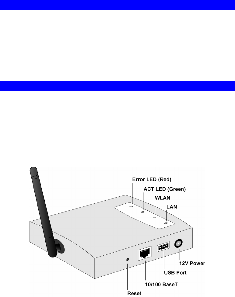
Physical Details
Details of the LEDs and connections are in this Chapter. Further details are contained in
Appendix A - Specifications.
PS801Hv2
• 1 USB Printer Port
• IEEE 802.11g/802.11b Wireless Station
• 10BaseT/100BaseTx LAN connection
Figure 1: PS801Hv2
Page 4
LED Indicators
The Print Servers have LED indicators on the top. The Error LED is red. The Status indicator
LED is green. The LED indicator modes are described in the following table.
Status LED
(Green) Error LED
(Red) Status Description
Off Off No power.
On Off Normal operation - Idle.
Flashing Off Normal operation - transmitting or receiving
packets from the network.
On On Hardware error.
Flashing Flashing Firmware upgrade in progress.
LED Description
WLAN Off - No Wireless connection available.
On - Wireless connection available.
Flashing - Transmitting or receiving data through the Wireless
LAN.
LAN Off - No LAN connection
On - LA N connection available.
Flashing - Transmitting or receiving data through the LAN.
Diagnostic Push Button
The button is recessed; a pin or paper clip can be used to press it. This button has 2 functions:
• Restore the factory default settings
• Print a test page containing all current settings.
To restore the factory default settings:
1. Turn the Print Server OFF.
2. Press and hold the diagnostic button. While pressing the button, switch the Print Server
ON.
3. If you continue pressing the button for 10 seconds, a diagnostic page will be printed,
showing the new (default) settings.
To generate a Diagnostic print out
1. Ensure that both the Print Server and the attached printer are ON.
2. Press the diagnostic button, and hold it in for 2 seconds.
3. The test page, containing the current settings, will be printed.
Note:
Page 5
PostScript printers are unable to print this page. If you have a PostScript printer, the test
page will not be printed.

Page 6
Chapter 2
LAN Installation
This chapter describes how to install the Print Server in your Local Area Network.
Procedure
1. Preparation
• Ensure the power is OFF. Do not connect the Print Server while power is On.
• Find the Default Server Name for your Print Server. The Default Server Name is shown on
a sticker on the base of the device. It consists of 8 letters and/or digits. Record this name; it
may be needed during configuration.
2. Connect the Printer
Use the cable supplied with your printer to connect the printer to the USB port on the Print
Server unit.
3. Connect the Network Cable
Connect the network cable to the 10/100BaseT LAN connector on the Print Server.
• To use the LAN interface, the LAN cable needs to be
inserted BEFORE powering ON.
• The Wired (LAN) interface should be used for initial
configuration.
• In the default Wireless "Infrastructure" mode, connecting a
LAN cable will disable the Wireless interface. To use both
the LAN and Wireless interfaces, the Wireless mode must
be changed to "Ad-hoc".
4. Power Up
Plug in the power adapter cable and power up. Start-up will take only a few seconds.
Use only the Power Supply unit provided with the Print Server. Using a different Power
Supply may cause damage.
5. Check the LEDs
• The Error LED should flash, then turn Off. When the Error LED goes off and the Status
LED remains lit or flashes, the Print Server is ready.
• The Error LED will remain flashing if the Print Server can't connect to the USB printer.
2

Page 7
Chapter 3
MFP Configuration
This chapter provides an overview of the configuration process.
Overview
The Print Server is designed to support many different platforms, and the configuration
required would depend upon the environment in which it is installed.
• The Print Server usually requires configuration, but if there's a DHCP server on your
network, then the device is just plug-and-play. A Windows-based setup Wizard is also
provided on the CD-ROM to simplify this task.
• PCs wishing to use the printer attached to the Print Server always require configuration.
See Chapter 4- Client Configuration for details.
Configuration Methods
The following methods are available to perform the required Print Server configuration:
• Windows-based Wizard - see below for details.
• Web-based setup - see Chapter 4 for details.
Advanced Configuration and Management
The BiAdmin management utility is provided for advanced configuration and management.
This program is installed by default when the Administrator install option is chosen. See
Chapter 5 for details on using BiAdmin.
Using the Windows Wizard
The Windows-based Wizard is supplied on the CD-ROM, and runs on Windows 95, 98, NT4.0,
ME, Windows 2000 and Windows XP.
Using this Wizard is the recommended method to configure the Print Server.
It can be used configure the Print Server for your Network environment, even if the Print
Server does not have a valid IP address.
Procedure
1. Insert the supplied CD-ROM into your drive. If the setup program does not start
automatically, run SETUP.exe in the root folder.
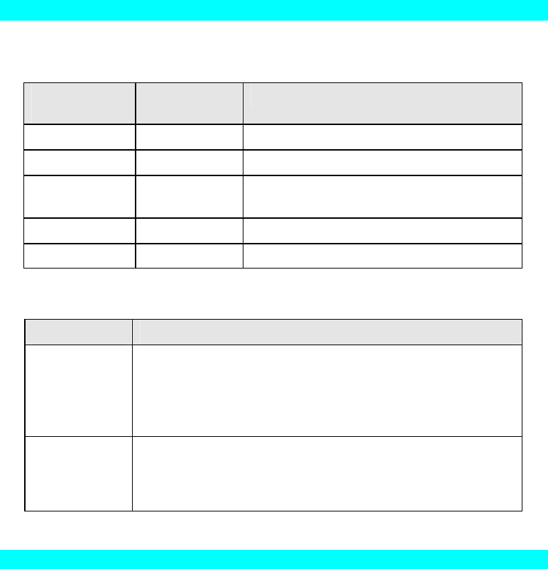
2. On the first screen, shown below, click Setup Wizard.
3
Page 8
Figure 2: MFP Screen
3. Click OK or Skip if all the setup procedures listed on the first screen are checked.
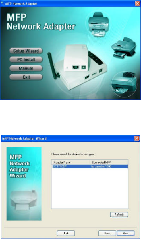
4. Select your MFP Network Adapter, then click Next to continue.
Figure 3: Adapter Screen
5. Click Next to configure the IP Address screen.
• Select Obtain IP Address automatically if your LAN has a DHCP Server, otherwise
select Use following IP address.
• For Use following IP address, enter an unused address from the range used on your
LAN.
Use the same Subnet Mask and Default Gateway as PCs on your LAN.
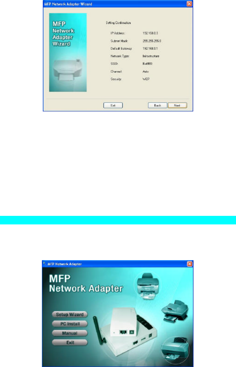
6. Click Next to see the following screen
Page 9
Figure 4: Status Screen
7. Click Next and Exit to continue to the final screen
8. Click Finish to save the data to the MFP Network Adapter.
If the desired MFP is not listed:
• Check that both the MFP Network Adapter and the printer are properly connected, and
powered on.
• Check that the proper Printer Driver has been installed.
Windows Setup
1. Insert the supplied CD-ROM into your drive. If the setup program does not start, run
SETUP.exe in the root folder.
2. Click PC Install to install the utility and bus driver.
Figure 5: Main Screen
3. Follow the prompts to complete the installation.
4. The MFP Network Adapter Utility will then run.
Page 10
MFP Network Adapter Utility Setup
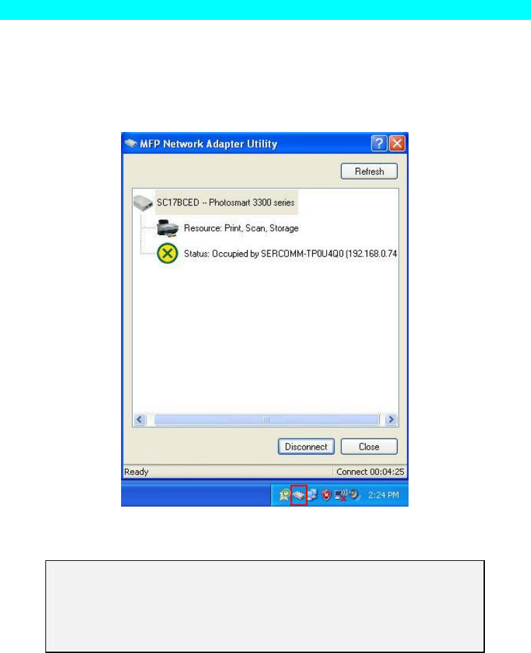
1. The program will search for the MFP Printer Servers on the network, and the MFP
Network Adapter Utility screen will be displayed.
• The names of the attached printer servers will be displayed if possible.
• If the MFP is occupied, the status field will display the information of the user and IP
address. Otherwise the default status should be "Ready" if the MFP is available.
Figure 6: MFP Icon
If your MFP Network Adapter is not listed:
• Check that both the MFP Network Adapter and the printer are properly
connected, and powered on.
• Check that the proper Printer Driver has been installed.
2. Click "Init MFP" button to configure the MFP for the first time. Normally, you only need
to do the configuration once.
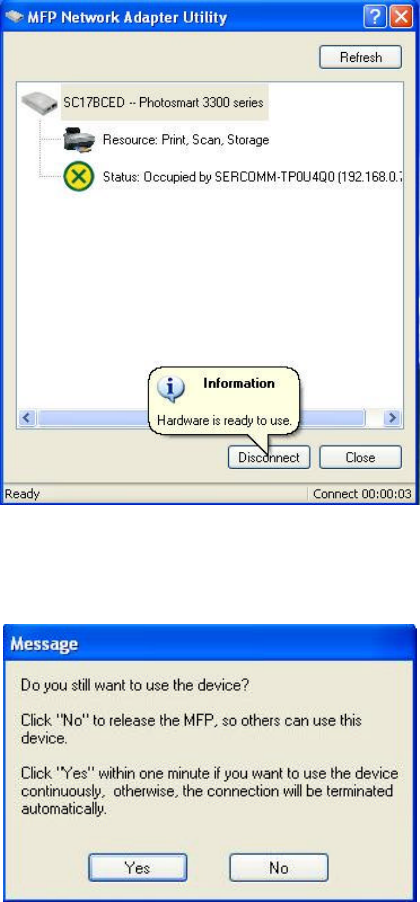
3. Once the MFP has been connected successfully, the button will show "Disconnect" instead
of "Connect".
Page 11
Figure 7: Utility Screen
4. Configuration is now complete.
Note: If MFP has been idled for 5 minutes after connected, you will see the following message
Figure 8: Idle Message
The MFP will be disconnected automatically if you don't respond to the message within
1minute.

Page 12
Chapter 4
Web-Based Management
This chapter explains how to use your Web Browser to configure the Print Server.
Overview
The Print Server incorporates the HTTP server. This allows you to connect to the Print Server
and configure it using your Web Browser. Most browsers should work, provided they support
tables and forms.
Preparation
Because it supports dynamic IP Address allocation using DHCP, BOOTP, or RARP, the Print
Server ships with an IP Address of 0.0.0.0.
This is NOT a valid IP Address.
Therefore, you must do ONE of the following:
• Check your DHCP server (if you have one), and determine the IP Address allocated to the
Print Server.
• Use the Diagnostic Button (if fitted) to print a report which includes the current IP
address. (Press the Diagnostic Button, and hold it for 2 seconds.)
• Use the Setup Wizard or another Print Server utility to allocate a valid IP Address to the
Print Server.
4
Page 13
Connecting to the Print Server
1. Start your Web Browser.
2. In the Address box, enter HTTP:// followed by the IP Address of the Print Server.
e.g.
http://192.168.0.100
3. You will then be prompted for the password. If no password has been set, just press ENTER.
4. Use the menu bar to move from one screen to another. Remember to save each screen
before changing to a different screen.
Configuration Screens
The following configuration screens are available.
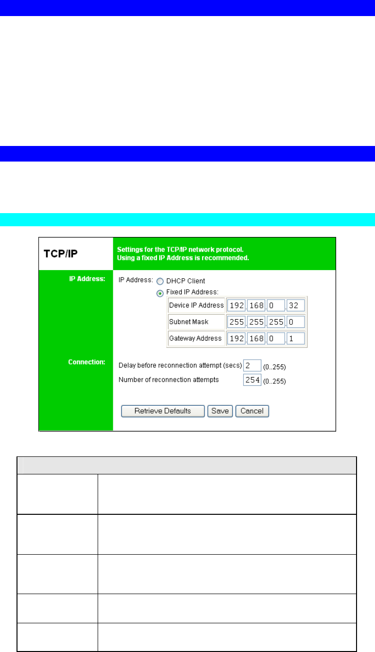
TCP/IP
Figure 9: TCP/IP Screen
IP Address
DHCP Client Select this if your LAN has a DHCP Server.
The Print Server will then automatically obtain an IP address
from the DHCP Server.
Fixed IP
Address Select this to assign a fixed IP address to the Print Server. If
selected, you must enter a the Device IP Address, Subnet
Mask, and Gateway.
Device IP
Address IP Address assigned to the Print Server.
Enter an unused IP address from the address range used on
your LAN.
Subnet Mask
Use the same values as PCs on your LAN (or on the same LAN
segment, if you have a Router).
Gateway
Address Use the same values as PCs on your LAN (or on the same LAN
segment, if you have a Router).

Page 14
Connection
Delay before
reconnection
attempt
Sets how long the Print Server should wait before retrying a
TCP/IP connection which is lost. Allowable values are from 0
to 255 seconds, with 2 as the default.
Number of
reconnection
attempts
Set how many attempts at reconnection will be made. After
that, the TCP/IP session will be terminated.
Allowable values are from 0 to 255, with 254 as the default.
Page 15
Wireless Configuration
There are 2 options on the menu for Wireless configuration - Basic and Security.
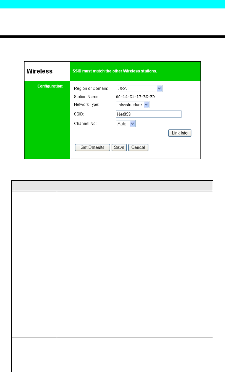
Wireless - Basic
The settings on this screen must match the other Wireless stations in order for communication
to occur.
Figure 10: Wireless Screen
Configuration
Region or
Domain Select your region from the drop-down list.
This field displays the region of operation for which the
wireless interface is intended. It may not be legal to operate the
router in a region other than the region shown here. If your
country or region is not listed, please check with your local
government agency for more information on which channels
you are allowed to use, and select a region, which allows those
channels. (The channel list changes according to the selected
region.)
Station name This is the same as the Device (Host) Name on the WAN
screen. On your PC, some Wireless status screens may display
this name as the Access Point in use.
Network Type Select the correct value for your Wireless LAN.
• Ad-hoc mode is used when there is no Wireless Access
Point, and each Wireless station communicates directly
with other Wireless stations.
• Infrastructure mode is used when each Wireless station
connects to the Wireless Access point. This also provides
access to the wired LAN.
SSID
(ESSID) To communicate, all Wireless stations MUST use the same
SSID/ESSID.
The default value is blank (null).
Note! The SSID is case sensitive.
Page 16
Channel No. In Infrastructure mode, this setting has not effect – the Access
Point determines the Channel used.
For Ad-hoc mode, select the value you wish to use on your
Wireless LAN. If you experience lost connections and/or slow
data transfers you may need to experiment with different
channels to see which is the best.
Link Info
Button Click this button to open a sub screen displaying link
information.
Wireless Security Screen
There are 3 options for Wireless security:
• Disabled - no data encryption is used.
• WEP - data is encrypted using the WEP standard.
• WPA-PSK - data is encrypted using the WPA-PSK standard. This is a later standard than
WEP, and provides much better security than WEP. Use this if possible.
• WPA2-PSK - this is a further development of WPA-PSK, and offers even greater security,
using the AES (Advanced Encryption Standard) method of encryption.
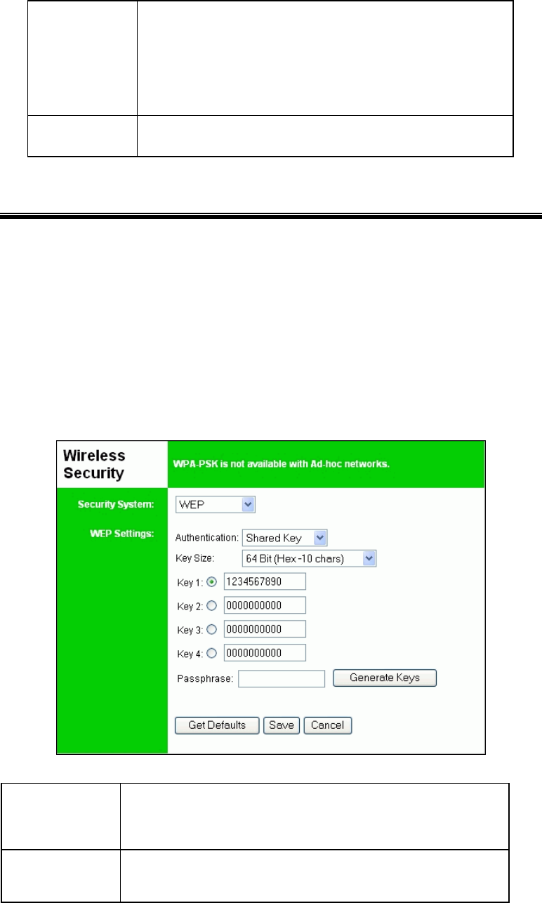
Wireless Security - WEP
If "WEP" is selected, the screen will look like the following example.
Figure 11: WEP Screen
Security
System WEP
The 802.11b standard. Data is encrypted before transmission, but
the encryption system is not very strong.
Authentication Select the appropriate value, as used on your Wireless LAN -
"Open System" or "Shared Key."
Page 17
Key Size Select the WEP Encryption level:
• 64-bit (sometimes called 40-bit) encryption
• 128-bit encryption (sometimes called 104 bit encryption)
This selection also allows you to choose the input type for the
keys – Hex or ASCII.
Keys • Use the radio buttons to select the default key.
• Enter the key value(s) you wish to use. Other stations must
have the same key values.
• Keys can be entered in Hex or ASCII, according to your Key
Size selection. Hex characters are the digits (0 ~ 9) and the
letters A ~ F.
Passphrase Enter some printable characters in the Passphrase field and click
the "Generate Keys" button to automatically configure the WEP
Key(s). For 64 bit keys, four keys fields will be generated. For
128 bit keys, only the selected WEP key will be generated.
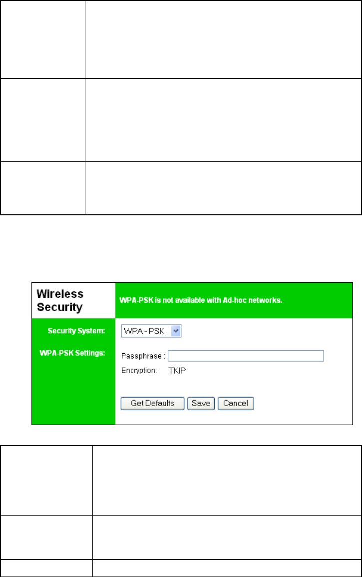
Wireless Security - WPA-PSK
If "WPA-PSK" is selected, the screen will look like the following example.
Figure 12: WPA-PSK Screen
Security
System WPA-PSK
Like WEP, data is encrypted before transmission. WPA is more
secure than WEP, and should be used if possible. WPA-PSK is
the version of WPA, which does NOT require a Radius Server
on your LAN.
Passphrase Enter the Keyword key value. Data is encrypted using a key
derived from the PSK. Other Wireless Stations must use the
same PSK. The PSK must be from 8 to 63 characters in length.
Encryption Other Wireless Stations must use the TKIP method.
Page 18
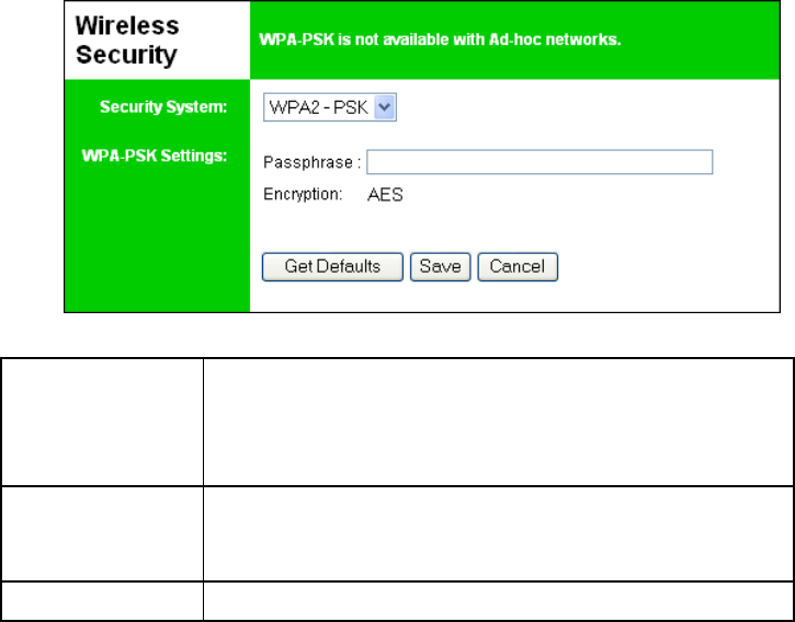
Wireless Security - WPA2-PSK
If "WPA2-PSK" is selected, the screen will look like the following example.
Figure 13: WPA2-PSK Screen
Security
System WPA2-PSK
This is a further development of WPA-PSK, and offers even
greater security, using the AES (Advanced Encryption
Standard) method of encryption.
Passphrase Enter the Keyword key value. Data is encrypted using a key
derived from the PSK. Other Wireless Stations must use the
same PSK. The PSK must be from 8 to 63 characters in length.
Encryption Other Wireless Stations must use the AES method.

Page 19
Other Screens
Server Status
This screen shows server system data and the current settings for all of the other screens. It is
read-only; no data can be input on this screen.
Printer Status
This screen displays the current status of each port. For each port, the following data is listed:
• Connected Printer- the model name of the printer connected to the port, if the printer
name is known. (If the printer is not bi-directional, this information is unavailable.)
• Status - the current status of the printer (On-line, Off-line, Out of paper)
• Printing Information - this will show either Idle or Printing.
Page 20
Appendix A
Specifications
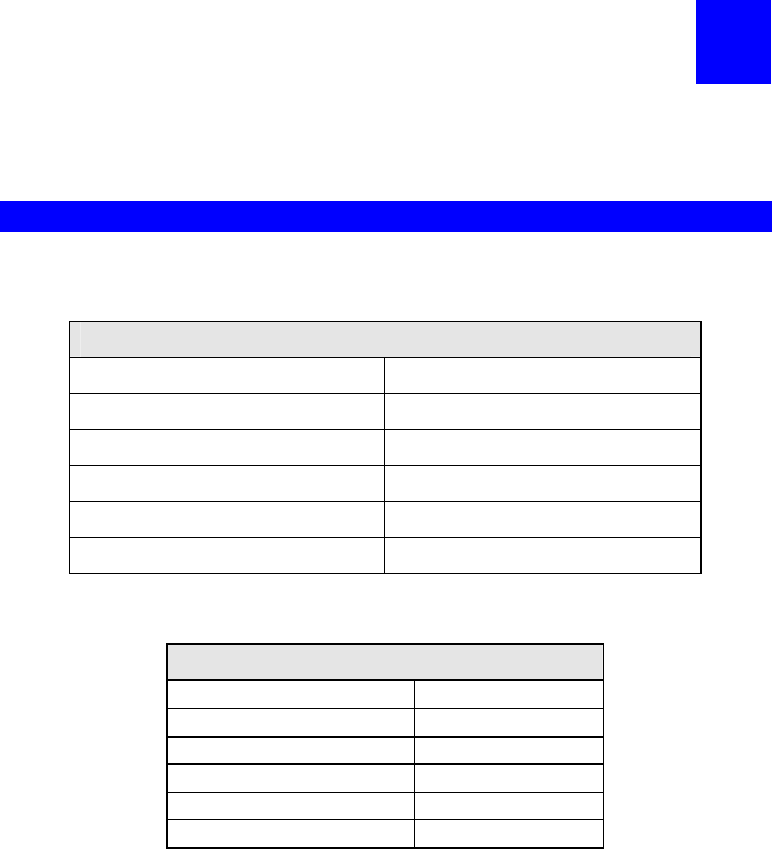
General Specifications
PS801Hv2 Print Server
Power Consumption 5.5w max.
External Power Adapter 5 V DC
LEDs 4
USB 2.0 Port 1
Ethernet Connecter 10/100BaseT
FCC / CE FCC, CE. Class B
Environmental Specifications
Operating Temperature 0 ~ 40°C
Storage Temp erature -10 ~ 70°C
Shipping Temperature -40 ~ 70°C
Operating Humidity 10 ~ 80%
Storage Humidity 5 ~ 90%
Shipping Humidity 5 ~ 100%
A
Page 21
71
FCC STATEMENT
This product has been tested and complies with the specifications for a Class B digital device, pursuant to Part 15
of the FCC Rules. These limits are designed to provide reasonable protection against harmful interference in a
residential installation. This equipment generates, uses, and can radiate radio frequency energy and, if not
installed and used according to the instructions, may cause harmful interference to radio communications.
However, there is no guarantee that interference will not occur in a particular installation. If this equipment does
cause harmful interference to radio or television reception, which is found by turning the equipment off and on,
the user is encouraged to try to correct the interference by one or more of the following measures:
Reorient or relocate the receiving antenna
Increase the separation between the equipment or devices
Connect the equipment to an outlet other than the receiver's
Consult a dealer or an experienced radio/TV technician for assistance
I
FCC RF Radiation Exposure Statement:
1. This Transmitter must not be co-located or operating in conjunction with any other antenna or transmitter.
2. This equipment complies with FCC RF radiation exposure limits set forth for an uncontrolled environment.
This equipment should be installed and operated with a minimum distance of 20 centimeters
You are cautioned that changes or modifications not expressly approved by the party responsible for compliance
could void your authority to operate the equipment.
between the radiator and your body.