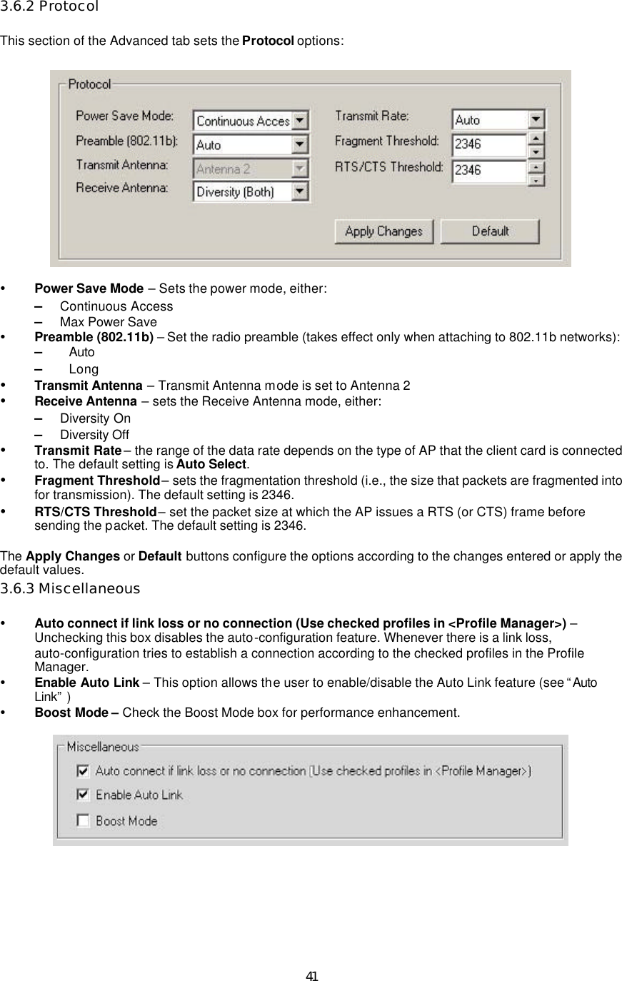
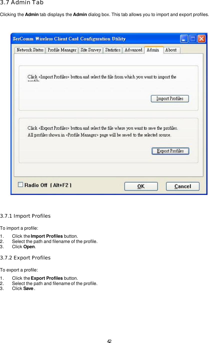
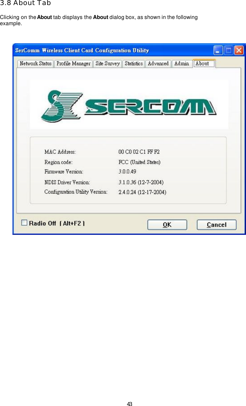
Sercomm CB801M 802.11g Wireless PC Card User Manual Users guide new
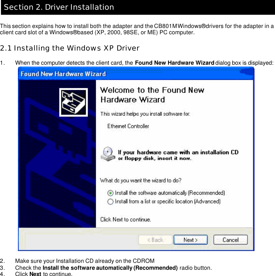
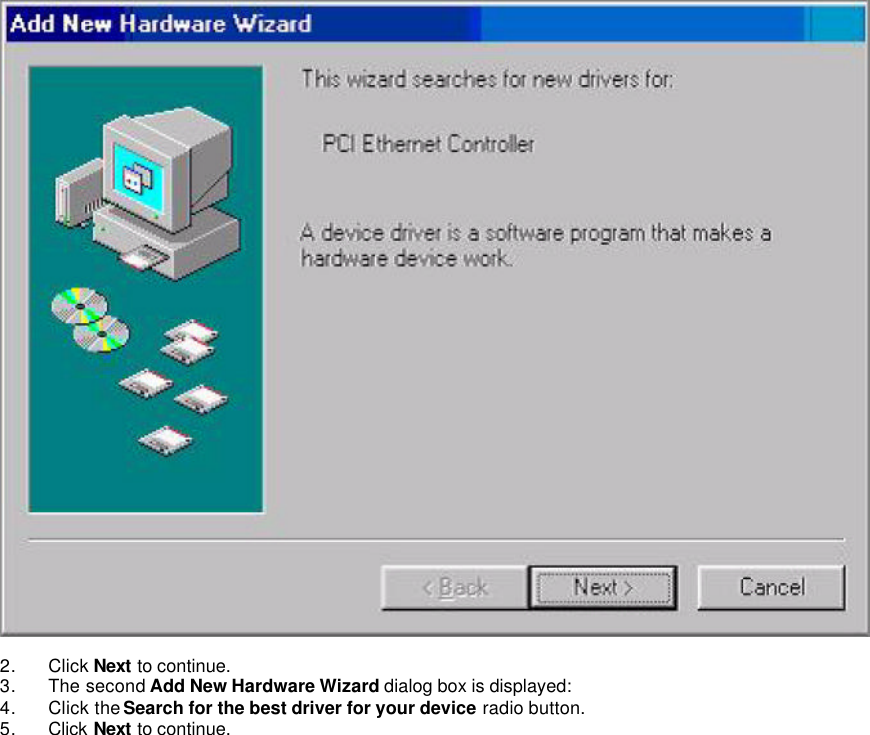
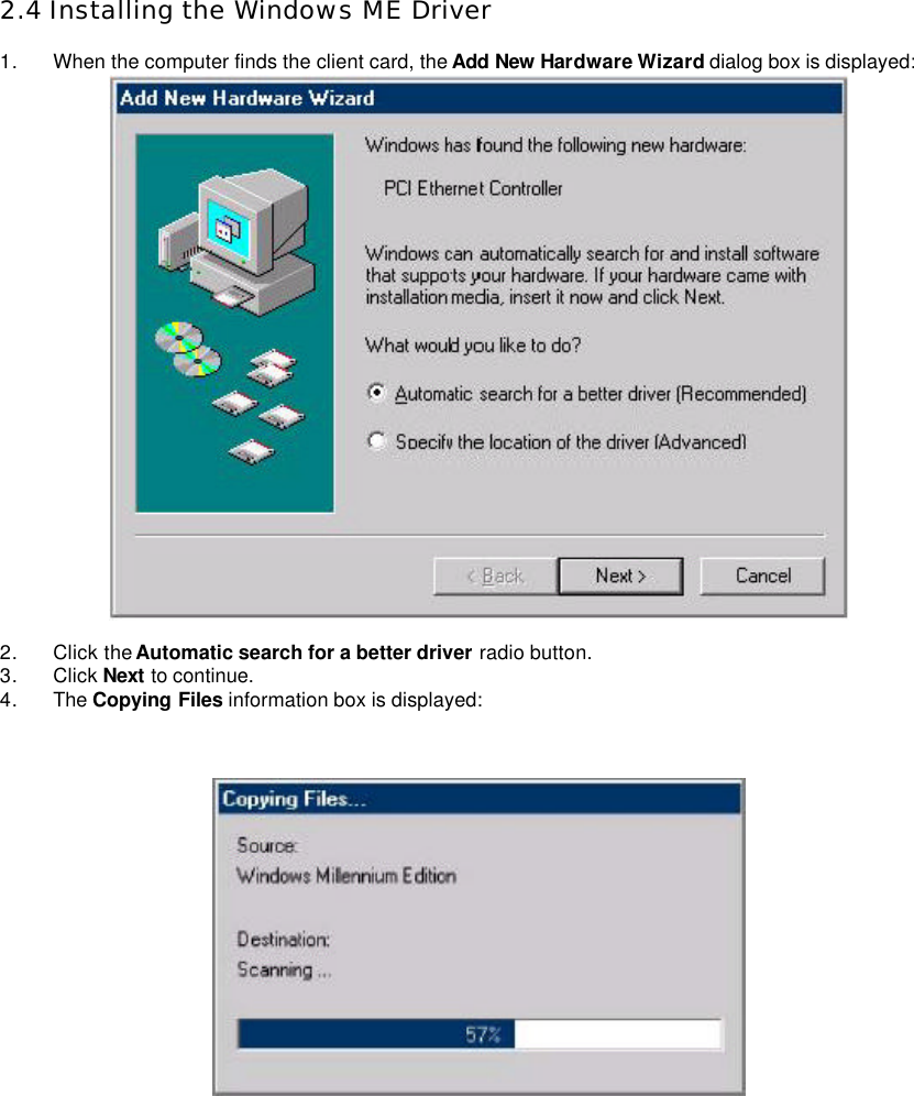
Sercomm Corporation 802.11g Wireless PC Card Users guide new
UserManual.wiki
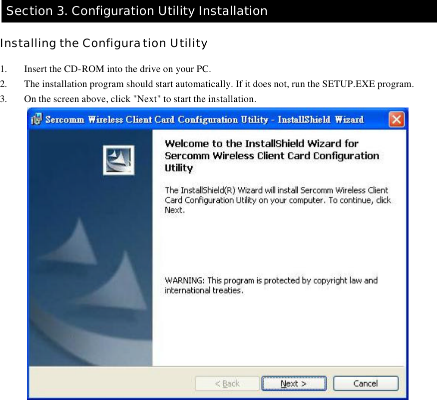
>
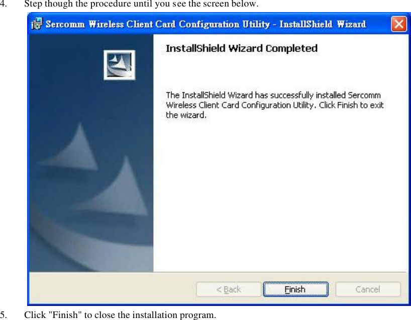
Sercomm
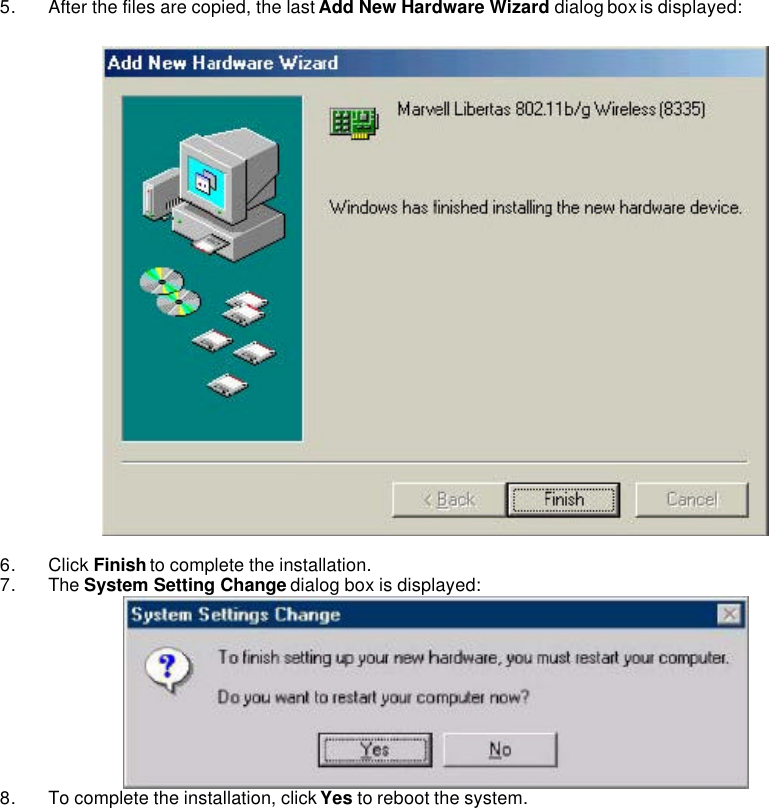
>
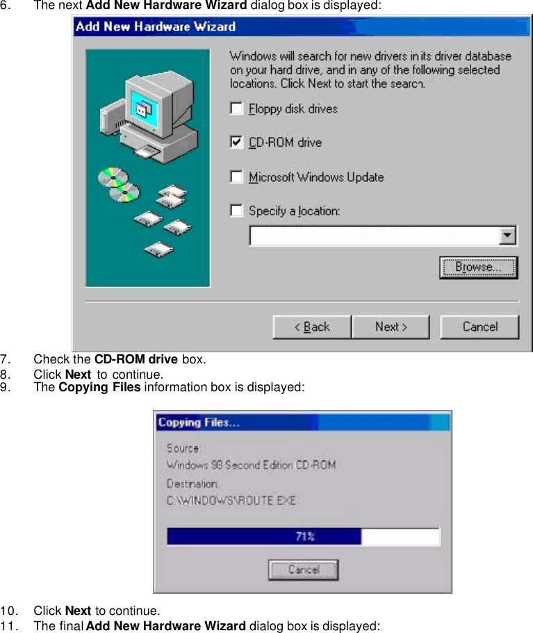
CB801M User Manual
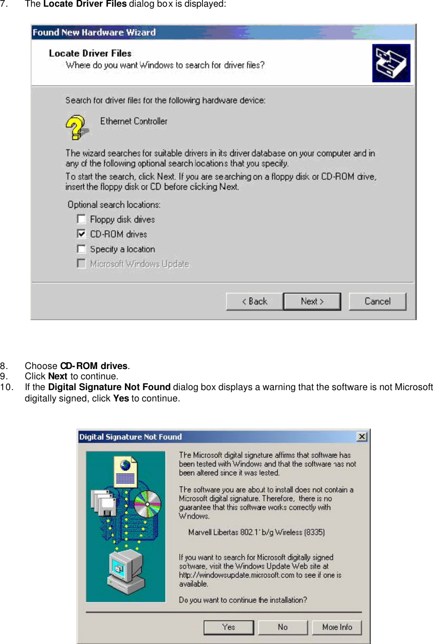
Revised Manual
Navigation menu
Upload a User Manual
Namespaces
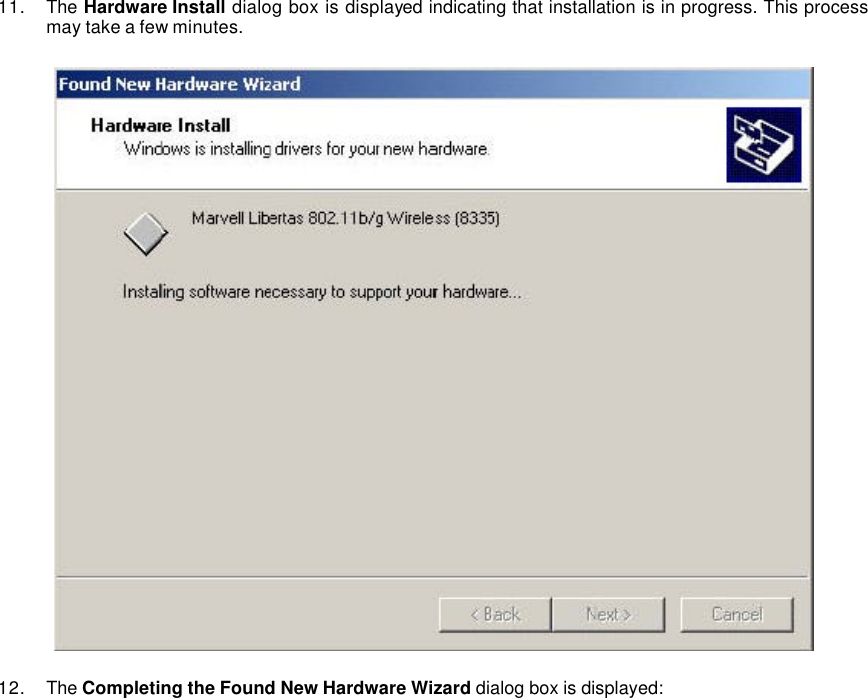
Wiki Guide
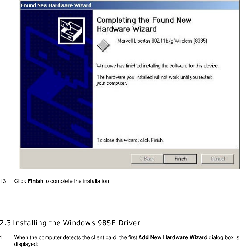
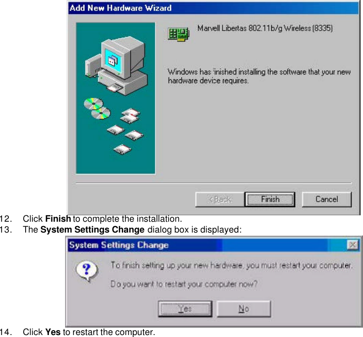
HTML
PDF
Info
Views
User Manual
Discussion / Help
Navigation