Sercomm CB801M 802.11g Wireless PC Card User Manual Users guide new
Sercomm Corporation 802.11g Wireless PC Card Users guide new
Sercomm >
Revised Manual

IEEE802.11g
Wireless PC Card
User Guide

Regulatory Approvals
FCC Statement
This equipment has been tested and found to comply with the limits for a Class B digital
device, pursuant to Part 15 of the FCC Rules. These limits are designed to provide reasonable
protection against harmful interference in a residential installation.
This equipment generates, uses and can radiate radio frequency energy and, if not installed and
used in accordance with the instructions, may cause harmful interference to radio communica-
tions. However, there is no guarantee that interference will not occur in a particular installation.
If this equipment does cause harmful interference to radio or television reception, which can be
determined by turning the equipment off and on, the user is encouraged to try to correct the
interference by one of the following measures:
Reorient or relocate the receiving antenna.
Increase the separation between the equipment and receiver.
Connect the equipment into an outlet on a circuit different from that to which the receiver
is connected.
Consult the dealer or an experienced radio/TV technician for help.
To assure continued compliance, any changes or modifications not expressly approved by the
party responsible for compliance could void the user's authority to operate this equipment.
(Example - use only shielded interface cables when connecting to computer or peripheral
devices).
Channel
The Wireless Channel sets the radio frequency used for communication.
•Access Points use a fixed Channel. You can select the Channel used. This allows you to
choose a Channel which provides the least interference and best performance. In the USA
and Canada, 11 channel are available. If using multiple Access Points, it is better if adjacent
Access Points use different Channels to reduce interference.
• In "Infrastructure" mode, Wireless Stations normally scan all Channels, looking for an
Access Point. If more than one Access Point can be used, the one with the strongest
signal is used. (This can only happen within an ESS.)
• If using "Ad-hoc" mode (no Access Point), all Wireless stations should be set to use the
same Channel. However, most Wireless stations will still scan all Channels to see if there
is an existing "Ad-hoc" group they can join.
This device has been tested and meets the FCC RF exposure guidelines.
The maximum SAR value reported is 0.071 w/kg

Table of Contents
SECTION 1. INTRODUCTION................................................................................................................................3
1.1 OVERVIEW.............................................................................................................................................................. 3
1.2 INSTALLATION....................................................................................................................................................... 3
1.2.1 Adapter Windows Driver............................................................................................................................ 3
1.2.2 Adapter Configuration Utility................................................................................................................... 3
1.3 SYSTEM REQUIREMENTS..................................................................................................................................... 3
1.4 PACKAGE CONTENTS............................................................................................................................................ 3
SECTION 2. DRIVER INSTALLATION...............................................................................................................4
2.1 INSTALLING THE WINDOWS XP DRIVER............................................................................................................ 4
2.2 INSTALLING THE WINDOWS 2000 DRIVER ........................................................................................................ 6
2.3 INSTALLING THE WINDOWS 98SE DRIVER .....................................................................................................11
2.4 INSTALLING THE WINDOWS ME DRIVER........................................................................................................15
SECTION 3. CONFIGURATION UTILITY INSTALLATION ....................................................................17
INSTALLING THE CONFIGURATION UTILITY...........................................................................................................17
SECTION 3. CONFIGURATION UTILITY.......................................................................................................19
3.1 OVERVIEW............................................................................................................................................................19
3.1.1 Windows XP Users ....................................................................................................................................19
3.1.2 Running the Configuration Utility..........................................................................................................20
3.1.3 Tray Status Icons.......................................................................................................................................20
3.1.4 Configuration Utility Window.................................................................................................................20
3.1.5 Auto Link Feature......................................................................................................................................20
3.1.6 WPA Configuration...................................................................................................................................20
3.2 NETWORK STATUS TAB ......................................................................................................................................22
3.2.1 Select Profile..............................................................................................................................................22
3.2.2 Link Information........................................................................................................................................23
3.2.3 Signal Strength / Wireless Mode Indicator............................................................................................24
3.2.4 Internet Protocol (TCP/IP)......................................................................................................................24
3.2.5 Actual Throughput Performance ............................................................................................................25
3.2.6 Radio On/Off Box ......................................................................................................................................25
3.3 PROFILE MANAGER TAB....................................................................................................................................26
3.3.1 Network Info Tab .......................................................................................................................................27
3.3.2 Security Tab................................................................................................................................................28
3.3.3 Protocol.......................................................................................................................................................34
3.4 SITE SURVEY TAB................................................................................................................................................35
3.4.1 Access Point Filter....................................................................................................................................35
3.4.2 Site Survey List Window...........................................................................................................................36
3.4.3 Filter Button...............................................................................................................................................37
3.4.4 Refresh Button............................................................................................................................................37
3.5 STATISTICS TAB...................................................................................................................................................38
3.5.1 Signal Strength...........................................................................................................................................38
3.5.2 Transmit Window.......................................................................................................................................38
3.5.3 Receive Window.........................................................................................................................................39
3.6 ADVANCED TAB...................................................................................................................................................40
3.6.1 CB801M Wireless Card ............................................................................................................................40
3.6.2 Protocol.......................................................................................................................................................41
3.6.3 Miscellaneous............................................................................................................................................41
3.7 ADMIN TAB..........................................................................................................................................................42
3.7.1 Import Profiles...........................................................................................................................................42
3.7.2 Export Profiles...........................................................................................................................................42
3.8 ABOUT TAB..........................................................................................................................................................43
3.9 AUTO LINK...........................................................................................................................................................44
APPENDIX A SPECIFICATIONS......................................................................................................................45

Section 1. Introduction
1.1 Overview
This guide explains how to install the following hardware and software on a Microsoft® Windows® based
laptop computer:
Ÿ CB801M Client Card Adapter
Ÿ CB801M Adapter Driver for Windows XP, 2000, 98SE, or ME
Ÿ CB801M Wireless Adapter Configuration Utility
1.2 Installation
The installation procedure includes four main steps:
1. Install the Driver
2. Install the Configuration Utility
1.2.1 Adapter Windows Driver
The Windows XP, 2000, 98SE, or ME driver for the adapter provides the interface between the CB801M and
the desktop or laptop computer.
Section 2. “Driver Installation" gives detailed instructions on how to install the adapter Windows driver.
1.2.2 Adapter Configuration Utility
The Configuration Utility is used to configure the adapter. Section 3. "Configuration Utility Installation"
explains how to install the utility.
1.3 System Requirements
The minimum system requirements for installing and using the adapter are as follows:
Ÿ Microsoft Windows XP, 2000, 98SE, or ME Operating System
Ÿ 400 MHz or higher CPU
Ÿ 128 MB of RAM
Ÿ 800 Kbytes of free disk space for installation of the driver and configuration utility
Ÿ CD-ROM drive
Ÿ Windows Driver User’s Manual
1.4 Package Contents
The package includes the following items:
. TBD
Section 2. Driver Installation
This section explains how to install both the adapter and the CB801M Windows® drivers for the adapter in a
client card slot of a Windows® based (XP, 2000, 98SE, or ME) PC computer.
2.1 Installing the Windows XP Driver
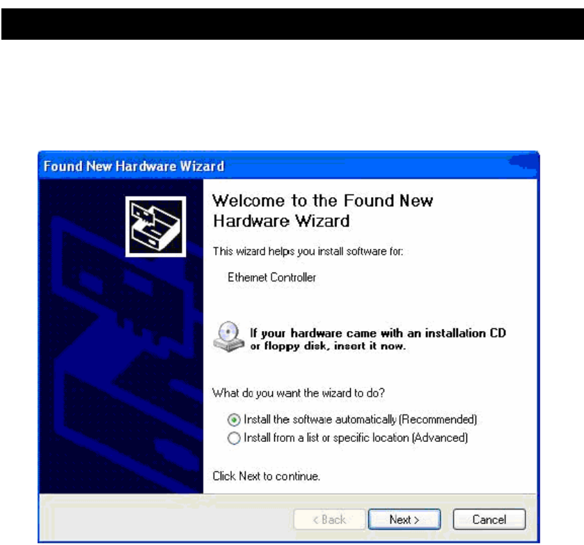
1. When the computer detects the client card, the Found New Hardware Wizard dialog box is displayed:
2. Make sure your Installation CD already on the CDROM
3. Check the Install the software automatically (Recommended) radio button.
4. Click Next to continue.
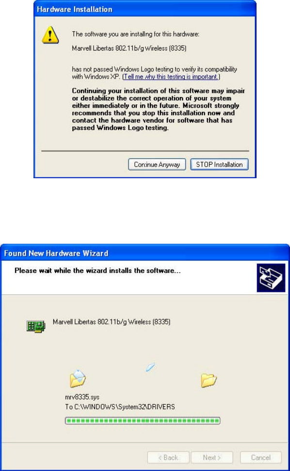
5. If the Hardware Installation dialog box displays a warning that the software has not passed Windows
Logo Testing, click Continue Anyway.
6. The Please wait while the wizard installs the software dialog box is displayed:
7. Click Next to continue.
8. The Completing the Found New Hardware Wizard dialog box is displayed:
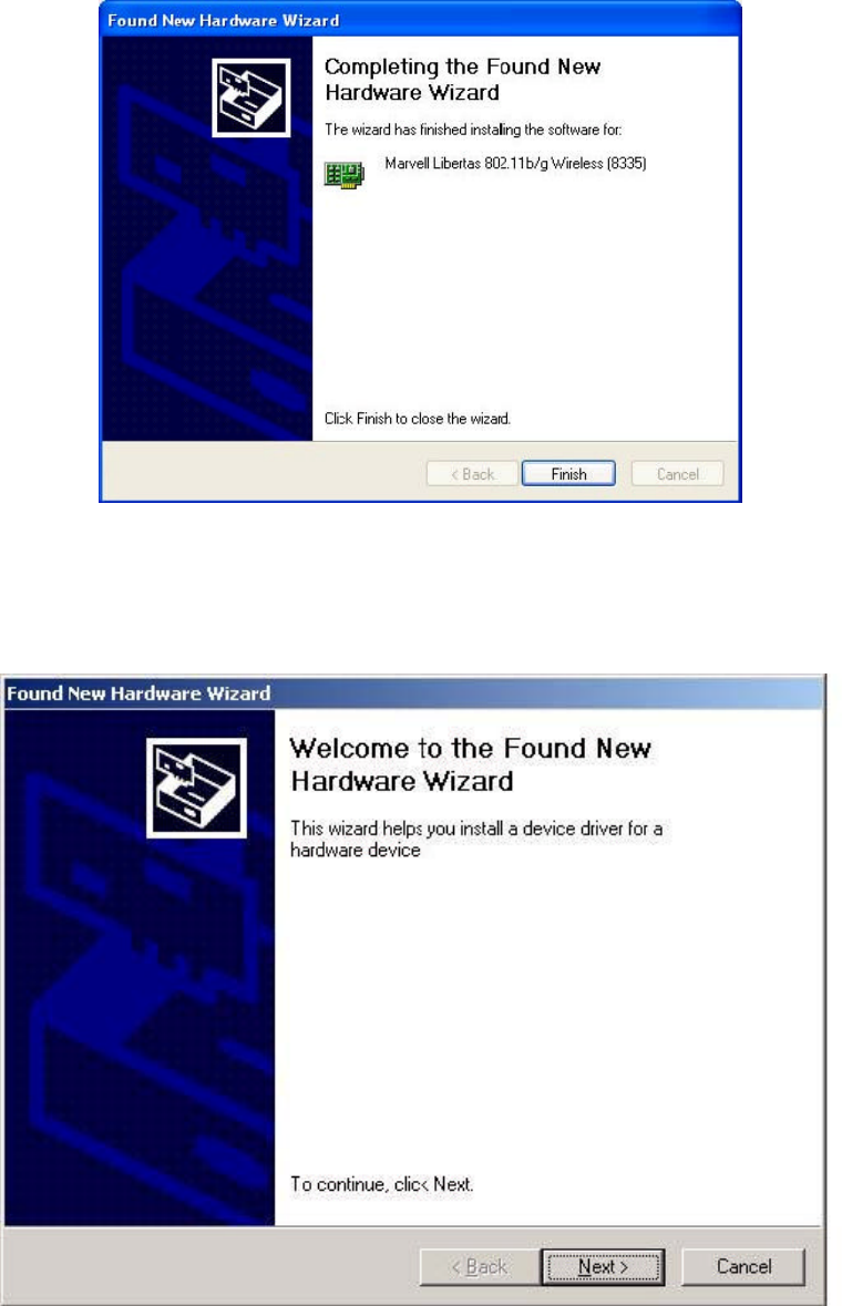
9. Click Finish to complete the installation.
2.2 Installing the Windows 2000 Driver
1. When the computer detects the Client Card, the Found New Hardware Wizard dialog box is
displayed:
2. Check the Install from a list or specific location (Advanced) radio button.
3. Click Next to continue.
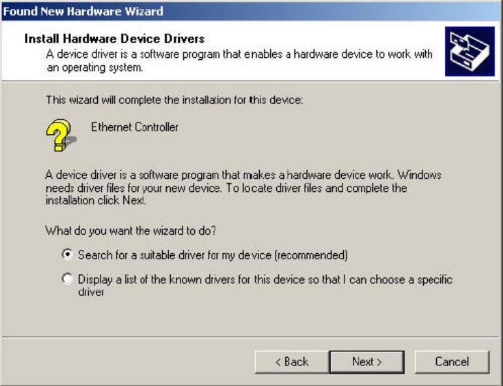
4. The Install Hardware Device Drivers dialog box is displayed:
5. Click the Search for a suitable driver for my device radio button.
6. Click Next to continue.
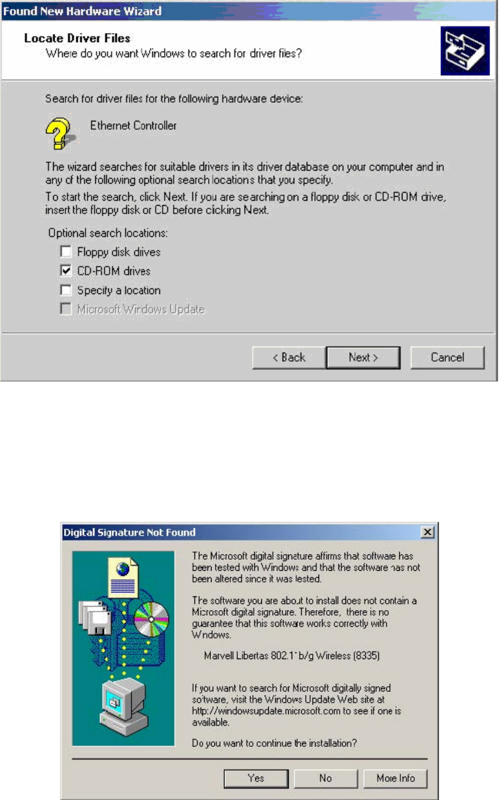
7. The Locate Driver Files dialog box is displayed:
8. Choose CD-ROM drives.
9. Click Next to continue.
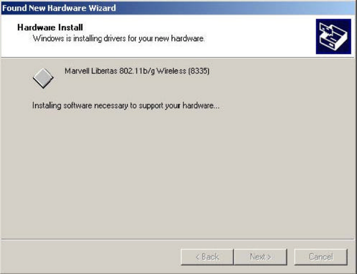
10. If the Digital Signature Not Found dialog box displays a warning that the software is not Microsoft
digitally signed, click Yes to continue.
11. The Hardware Install dialog box is displayed indicating that installation is in progress. This process
may take a few minutes.
12. The Completing the Found New Hardware Wizard dialog box is displayed:
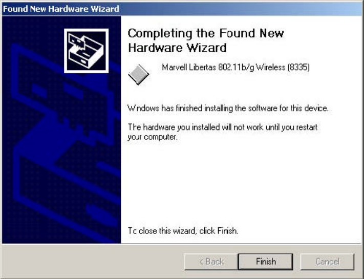
13. Click Finish to complete the installation.
2.3 Installing the Windows 98SE Driver
1. When the computer detects the client card, the first Add New Hardware Wizard dialog box is
displayed:
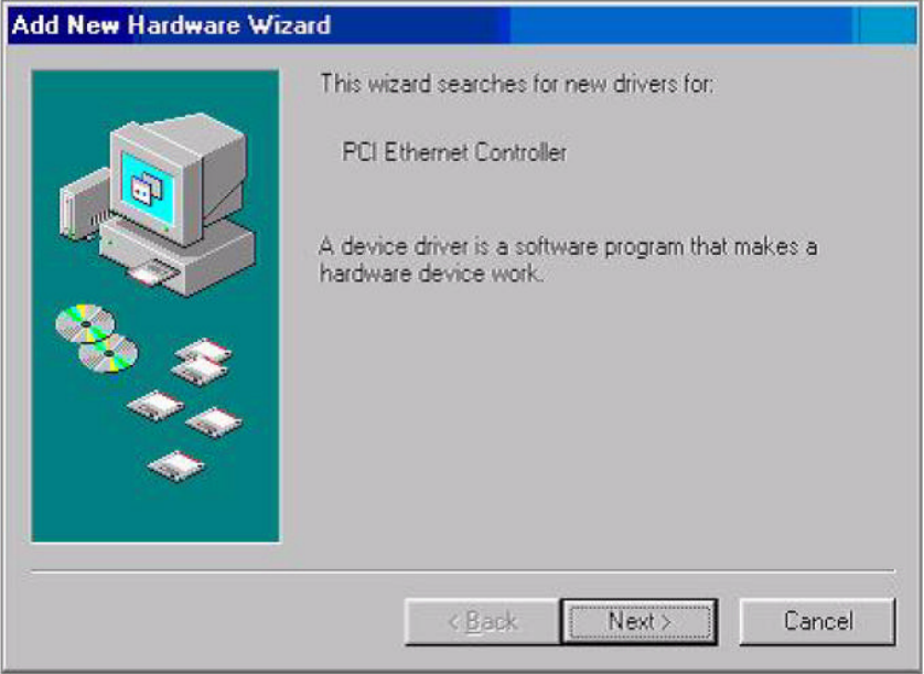
2. Click Next to continue.
3. The second Add New Hardware Wizard dialog box is displayed:
4. Click the Search for the best driver for your device radio button.
5. Click Next to continue.
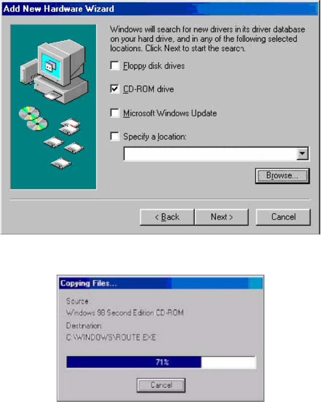
6. The next Add New Hardware Wizard dialog box is displayed:
7. Check the CD-ROM drive box.
8. Click Next to continue.
9. The Copying Files information box is displayed:
10. Click Next to continue.
11. The final Add New Hardware Wizard dialog box is displayed:
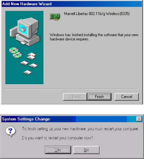
12. Click Finish to complete the installation.
13. The System Settings Change dialog box is displayed:
14. Click Yes to restart the computer.
2.4 Installing the Windows ME Driver
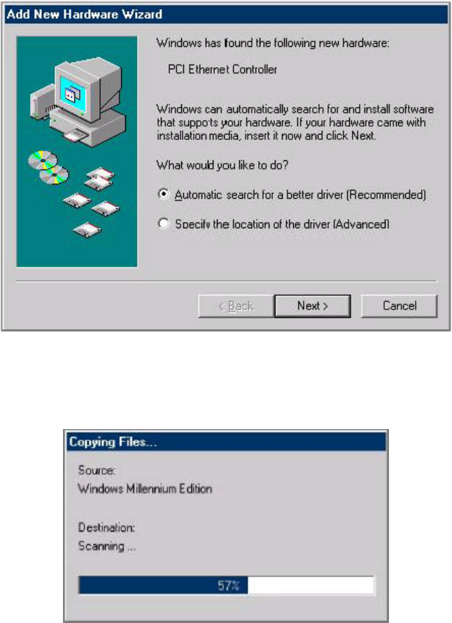
1. When the computer finds the client card, the Add New Hardware Wizard dialog box is displayed:
2. Click the Automatic search for a better driver radio button.
3. Click Next to continue.
4. The Copying Files information box is displayed:
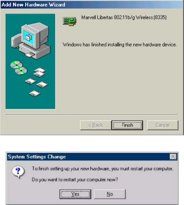
5. After the files are copied, the last Add New Hardware Wizard dialog box is displayed:
6. Click Finish to complete the installation.
7. The System Setting Change dialog box is displayed:
8. To complete the installation, click Yes to reboot the system.
Section 3. Configuration Utility Installation
Installing the Configuration Utility
1. Insert the CD-ROM into the drive on your PC.
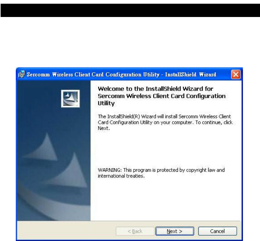
2. The installation program should start automatically. If it does not, run the SETUP.EXE program.
3. On the screen above, click "Next" to start the installation.
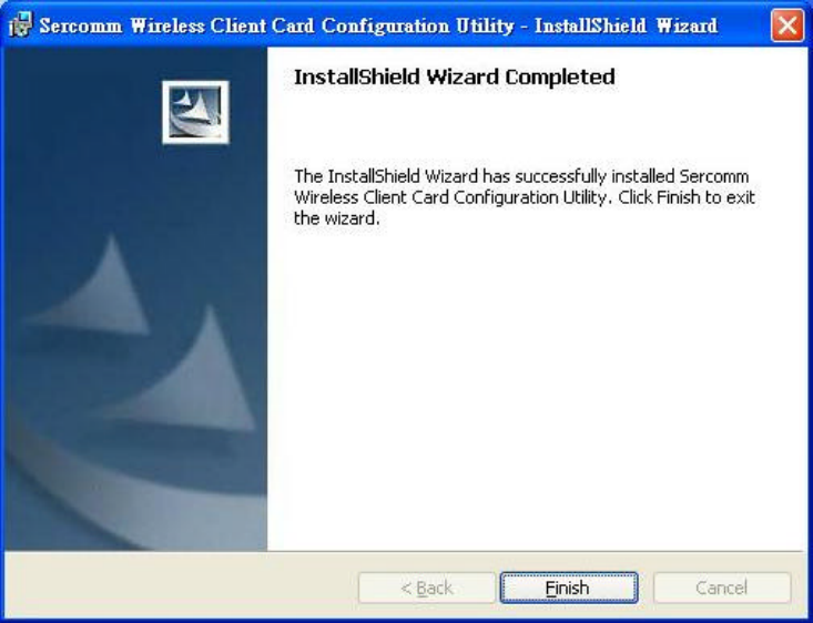
4. Step though the procedure until you see the screen below.
5. Click "Finish" to close the installation program.
Section 3. Configuration Utility
3.1 Overview
The CB801M Wireless Adapter Configuration Utility is a Microsoft® Windows® application that allows
configuration and management of the CB801M client cards. The Configuration Utility sets up profiles and
performs other wireless network management tasks. See the Installation Guide for instructions on how to
install the Configuration Utility.
3.1.1 Windows XP Users
For Windows XP, use either the Zero Configuration Utility or the Marvell Configuration Utility to configure
the CB801M wireless adapter cards.
To use the CB801M Configuration Utility:
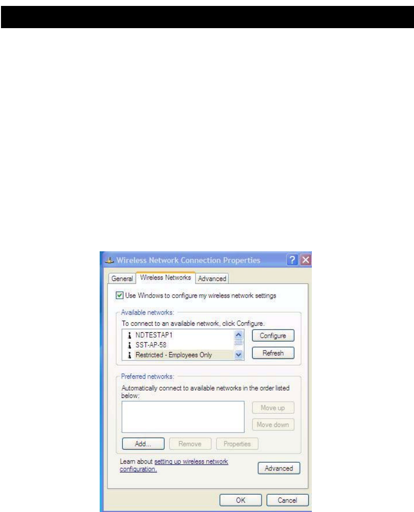
1. 1. Open the Zero Configuration Utility Window
2. 2. Uncheck the “Use Windows to configu re my wireless settings” checkbox.
When the CB801M Configuration Utility is opened, the Windows XP Zero Configuration Utility will be
closed automatically by the CB801M Configuration Utility.
Once the user exits the CB801M Configuration Utility, the Windows XP Zero Configuration Utility is restored
to managing the wireless configuration.
3.1.2 Running the Configuration Utility
Once installed, the Configuration Utility is accessed from the Start menu in the following ways:
Ÿ Start > SerComm Client Configuration Manager
Ÿ Start > Programs > SerComm 802.11g Client > SerComm Client Configuration Manager)
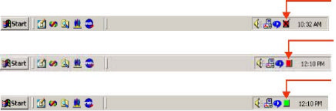
3.1.3 Tray Status Icons
Different icons in the system tray indicate the status of the wireless connection:
3.1.4 Configuration Utility Window
The Configuration Utility window displays the following tabs:
Ÿ Network Status – displays the status of the network to which the user is connected. The
Configuration Utility initializes on this page. See “Network Status Tab” for details.
Ÿ Profile Manager – displays the current profiles and allows the user to set attributes for network
type, security options, and protocols, as well as create/modify/delete profiles. See “Profile
Manager Tab” for details.
Ÿ Site Survey – shows a list of all of the stations w ithin range of the adapter. See “Site Survey Tab”
for details.
Ÿ Statistics – displays the statistics of the current session. See “Statistics Tab” for details.
Ÿ Advanced – allows you to set protocol parameters. See “Advanced Tab” for details.
Ÿ Admin – allows you to import and export profiles. See “Admin Tab” for details.
Ÿ About – gives the version number for the Configuration Utility. See “About Tab” for details.
The following subsections explain how to use the Configuration Utility.
3.1.5 Auto Link Feature
TBD
3.1.6 WPA Configuration
3.1.6.1 Security Infrastructure Setup
Implementing a security infrastructure to monitor physical access to WLAN networks is more difficult than
monitoring access on wired networks. Unlike wired networks where a physical connection is required,
anyone within range of a wireless Access Point can send and receive frames, as well as listen for frames
being sent.
IEEE 802.11 defines a set of standards and protocols for use in minimizing the security risks on wireless
networks. Two of the security standards are as follows:
Ÿ 802.1x — 802.1x authentication provides authenticated access to 802.11 wireless networks and
Adapter
Unplugged
(Red with “X” mark)
Not Connected
(Red)
Connected
(Green)
to wired Ethernet networks. 802.1x minimizes wireless network security risks by providing user
and computer identification, centralized authentication, and encryption services based on the
WEP algorithm. 802.1x supports Extensible Authentication Protocol (EAP). EAP allows the use
of different authentication methods, such as smart cards and certificates.
Ÿ Wi-Fi Protected Access (WPA) — WPA is an implementation based on a subset of the 802.11i
standard. WPA provides enhanced security for wireless networks when used with the TKIP and
the Message Integrity Check (MIC) algorithms.
3.1.6.2 WPA Connectivity
The CB801M Configuration Utility currently supports the following Authentication Modes:
Ÿ WPA-PSK
Ÿ 802.1x EAP/TLS
Ÿ 802.1x PEAP See “Security Tab” for details on configuring security options.
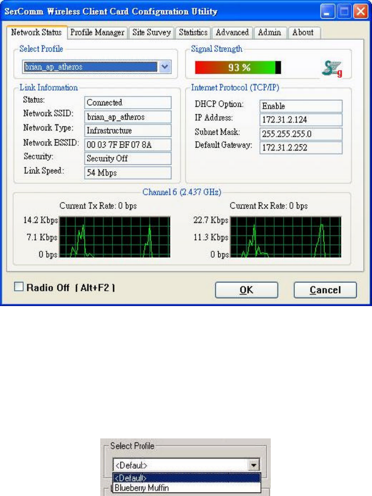
3.2 Network Status Tab
The Network Status tab displays the status of the network. When the Wireless Client Card Configuration
Utility initializes, it displays the Network Status tab:
3.2.1 Select Profile
The Select Profile window displays the name of the profile in use. Additional information about the profile is
provided in the Profile Manager.
Select one of the profiles previously defined by clicking the down arrow and highlighting a profile from the
pulldown list.
Profiles are created, modified, and deleted through the Profile Manager.
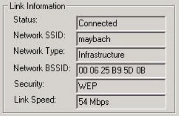
3.2.2 Link Information
The Link Information section contains the current information about the wireless
connection:
Ÿ Status – the status of the wireless network connection:
– Card Unplugged – adapter plugged in, but not recognized
See “Troubleshooting” on page 39 for possible solutions.
– Connected – card plugged in and connected to a wireless network
– Not connected – card plugged in, but cannot find a wireless network
See “Troubleshooting” on page 39 for possible solutions.
– No Radio – card plugged in, but the radio is turned off. Uncheck the Radio Off box to turn
the radio on.
Ÿ Network SSID – network SSID label (i.e., Network Name). The Network Name is a text string of
up to 32 characters.
Ÿ Network Type – type of environment to which you are connected The choices are
Infrastructure mode or Ad Hoc mode.
– Infrastructure Mode: In this mode, wireless clients send and receive information through
APs. When a wireless client communicates with another, it transmits to the AP. The AP
receives the information and rebroadcasts it. Other devices then receive the information.
APs are strategically located within an area to provide optimal coverage for wireless
clients. A large WLAN uses multiple APs to provide coverage over a wide area. APs can
connect to a LAN through a wired Ethernet connection. APs send and receive information
from the LAN through the wired connection.
– Ad Hoc Mode: In this mode, wireless clients send and receive information to other wireless
clients without using an AP. This type of WLAN only contains wireless clients. Us e Ad Hoc
mode to network computers at home or in small office, or to set up a temporary wireless
network for a meeting.
Ÿ Network BSSID – Network Basic Service Set Identifier. The BSSID is a 48-bit identity used to
identify a particular BSS within an area. In Infrastructure BSS networks, the BSSID is the MAC
address of the AP. In independent BSS or Ad Hoc networks, the BSSID is generated randomly.
Ÿ Security – reports the type and level of security set. The security level is set through the Profile
Setting of the Profile Manager tab. Configure WEP settings also through the Site Survey tab
when connecting to a network.
Ÿ Link Speed – connection speed, (i.e., 54 Mbps, 48 Mbps, etc.)
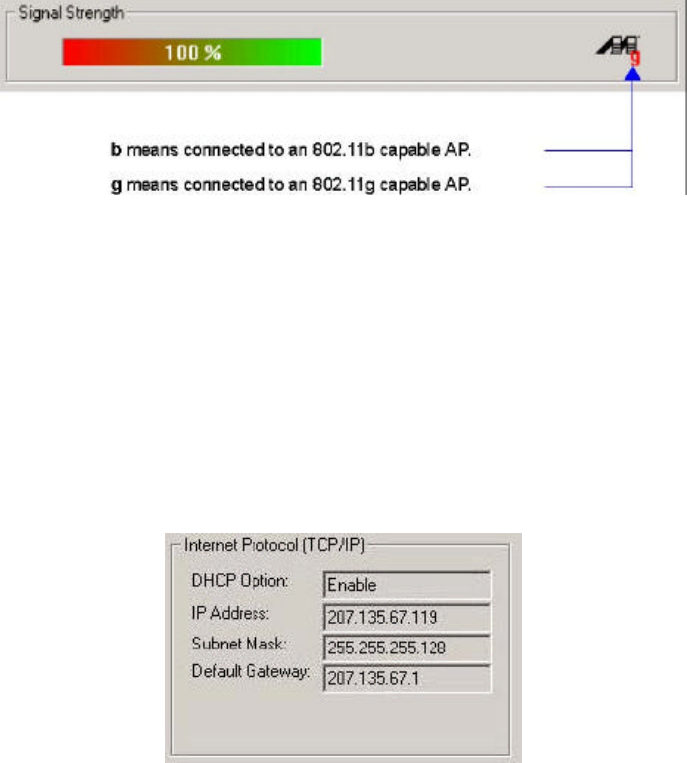
3.2.3 Signal Strength / Wireless Mode Indicator
The color-coded Signal Strength bar displays the signal strength of the last packet received by the adapter:
Signal strength is reported as a percentage. A signal in the red indicates a bad connection. A signal in the
green indicates a good connection.
The Wireless Mode indicator shows the data rates the client card operates. There are two modes: 802.11b
and 802.11g (backward compatible to 802.11b).
3.2.4 Internet Protocol (TCP/IP)
The Internet Protocol specifies the format of packets, also called datagrams, and the addressing scheme.
Most networks combine IP with a higher-level protocol called TCP, which establishes a virtual connection
between a destination and a source.
The parameters of the Internet Protocol are:
Ÿ DHCP Option – Dynamic Host Configuration Protocol. Eith er enabled or disabled.
Ÿ IP Address – an identifier for a computer or device on a TCP/IP network. The format of an IP
address is a 32-bit numeric address written as four numbers separated by periods. Each number
can be 0 to 255.
Ÿ Subnet Mask – a mask used to determine what subnet an IP address belongs to. An IP address
has two components, the network address and the host address. The first two numbers represent
the Class B network address, and the second two numbers identify a particular host on this
network.
Ÿ Default Gateway – the default node on a network that serves as an entrance to another network.
In enterprises, the gateway is the computer that routes the traffic from a workstation to the
outside network that is serving the Web pages. In homes, the gateway is the ISP that connects
the user to the internet.
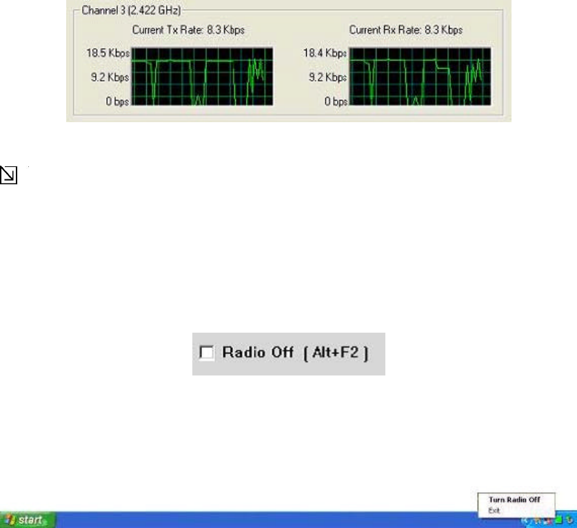
3.2.5 Actual Throughput Performance
This section of the Network Status tab displays the Current Tx Rate and the Current Rx Rate of the channel
being monitored.
Note
These are actual throughput diagrams (without the WLAN overhead delivered by the client card).
3.2.6 Radio On/Off Box
Clicking the Radio Off check box turns off the radio. Unchecking the box turns on the radio:
Another way to turn the radio on or off is to right-click the Configuration Utility icon in the System Tray and
click Turn Radio Off to turn the radio off. When the radio is off, click Turn Radio On to turn the radio back
on.
You can also use the system hot key Alt+F2 to turn the radio on/off.
When the radio is off, there is no radio activity, and the following property pages are disabled:
Ÿ Site Survey
Ÿ Statistics
Ÿ Advanced
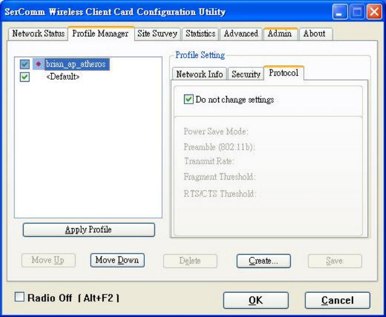
3.3 Profile Manager Tab
Clicking on the Profile Manager tab displays the Profile Manager dialog box. The Profile Manager displays
the p rofiles available and allows you to create, modify, and delete profiles:
Profile List Window
The window on the left side of this tab lists all of the profiles available. Highlighting a profile selects it. If the
Default box is checked, that profile is used in auto-configuration mode when the link is lost. If it is unchecked,
that profile is excluded in auto-configuration. The controls associated with this window are:
Ÿ Apply Profile – applies the profile selected. Apply the profile by double-clicking on the desired
profile.
Ÿ Move Up / Move Down – move the list up and down in the window. All profiles with the Network
Type set to Infrastructure are displayed before the profiles with the Network Type set to Ad Hoc.
Ÿ Delete – deletes a profile
Ÿ Create – creates a profile
Ÿ Save – saves changes made to a selected profile
Profile Setting The Profile Settings are used to display information about the profile selected in the Profile
List window. The information is divided into three tabs: Network Info, Security, and Protocol.
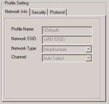
3.3.1 Network Info Tab
The Profile Manager initially displays the Network Info
tab:
The Network Info tab contains the following fields:
Ÿ Profile Name – the profile selected.
Ÿ Network SSID – the network SSID label.
Ÿ Network Type – the type of environment to which you are connected. The choices are
Infrastructure mode or Ad Hoc mode.
Ÿ Channel – the channel being used.
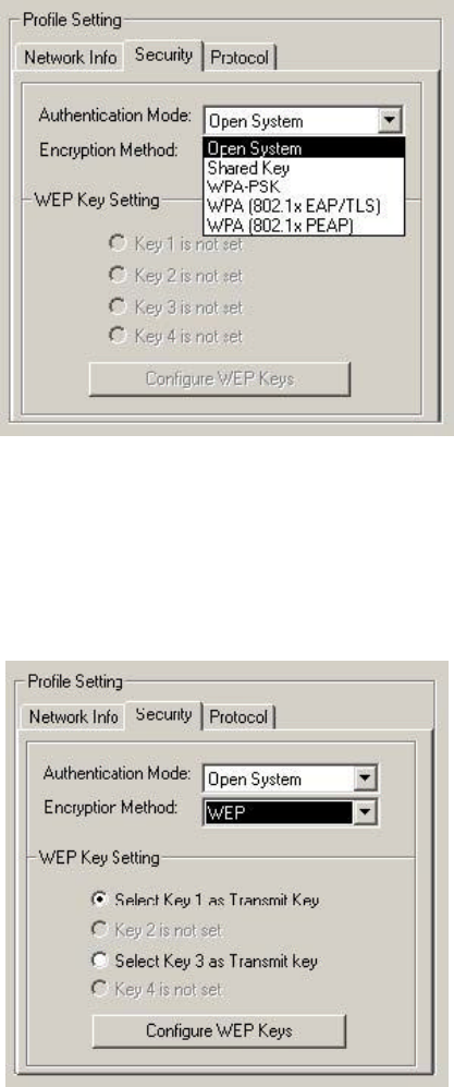
3.3.2 Security Tab
This section describes the Security tab configuration. See Section 2.1.6 "WPA Configuration" for
information on security infrastructure and WPA connectivity . Clicking the Security tab displays the security
options:
The Security tab contains the following fields:
Ÿ Authentication Mode – options are Open System, Shared Key, WPA-PSK, WPA 802.1x
EAP/TLS, and WPA 802.1x PEAP. To connect to an AP through the Radius Server, the user can
select either WPA 802.1x EAP/TLS or WPA 802.1x PEAP as the Authentication Mode.
Ÿ Encryption Method – options are TKIP, WEP, or Security Off, depending on the Authentication
Mode.
Ÿ WEP Key Setting – if WEP Encryption Method is selected, the WEP keys can be configured:
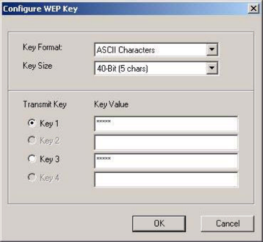
3.3.2.1 Configure WEP Keys
Clicking the Configure WEP Keys button displays the Configure WEP Key dialog
box:
Ÿ Key Format – either ASCII characters or hexadecimal digits.
Ÿ Key Size – 40-bit or 104-bit:
– 40-bit, 5 character ASCII key size (40-bit, 10 character hexadecimal)
– 104-bit, 13 character ASCII key size (104-bit, 26 character hexadecimal)
Ÿ Transmit Keys – there are four transmit keys. The key value is displayed in ASCII or hexadecimal,
depending on the format selected. Likewise, the key size shown depends on the key size selected.
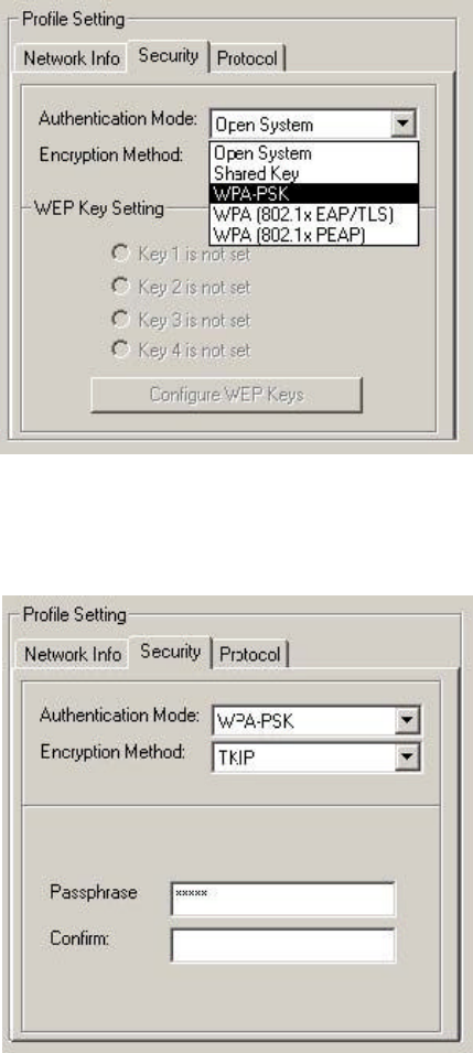
3.3.2.2 WPA-PSK Support in Infrastructure Mode
Ÿ In Infrastructure Mode, if WPA-PSK is selected as the Authentication Mode, TKIP is automatically
selected as the Encryption Method.
Ÿ Enter the network passphrase in the “Passphrase” and “Confirm” fields.
Ÿ WPA-PSK is not supported in Ad-Hoc network mode.
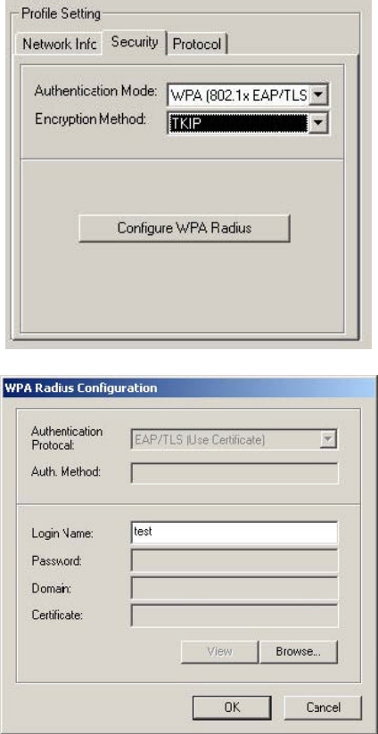
3.3.2.3 WPA (802.1x EAP/TLS) Support in Infrastructure Mode
To connect to an AP through the Radius Server, the user can select WPA 802.1x EAP/TLS as the
Authentication Mode.
1. In Infrastructure Mode, the user can select TKIP or WEP as the Encryption Method.
2. Click the Configure WPA Radius button to configure security settings.
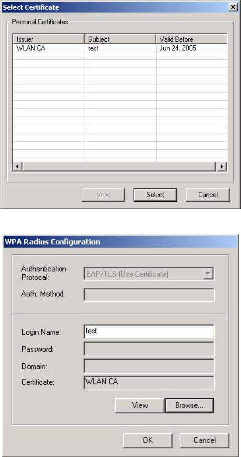
3. Click the Browse button to activate the dialog for selecting a certificate.
4. Before clicking the OK button to exit the dialog, make sure that the Login Name is entered.
33
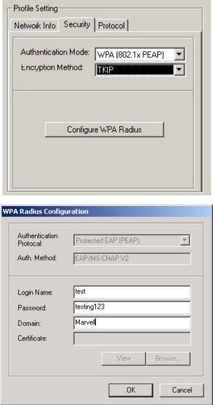
3.3.2.4 WPA (802.1x PEAP) Support in Infrastructure Mode
To connect to an AP through the Radius Server, the user can select WPA 802.1x PEAP as the Authentication
Mode. In Infrastructure Mode, the user can then select TKIP or WEP as the Encryption Method.
1. Click on the Configure WPA Radius button to configure security settings.
2. Make sure to enter all of the required information.
34
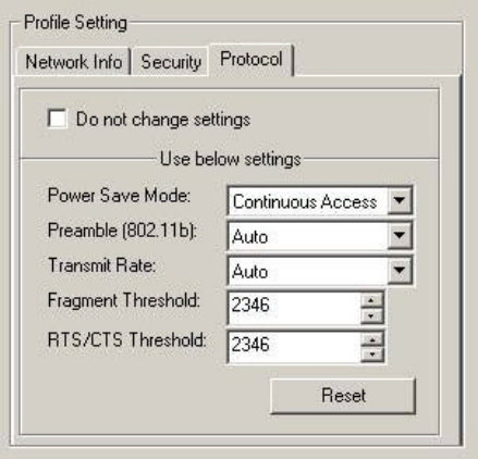
3.3.3 Protocol
Set or change protocol information from the Protocol tab.
Do not change settings
If this box is checked, the protocol setting is not changed when the profile is applied.
Use below settings
Some of the protocol settings below can be changed if the Do not change setting box is unchecked:
Ÿ Power Save Mode – Sets the power mode. Available options are Continuous Access or Max
Power Save. The default is Continuous Access.
Ÿ Preamble (802.11b) – Sets the Radio Preamble to Auto or Long. This option takes effect
only when attaching to an 802.11b network.
Ÿ Transmit Rate – The range of the data rate depends on the type of AP that the client card is
connected to. The default setting is Auto Select.
Ÿ Fragment Threshold – Sets the fragmentation threshold (the size that packets are fragmented
into for transmission). The default setting is 2346.
Ÿ RTS/CTS Threshold – Sets the packet size at which the AP issues a Request-To-Send (or
Clear-to-Send) frame before sending the packet. The default setting is 2346.
Ÿ Reset button – Clicking Reset returns the protocol settings to their default values.
35
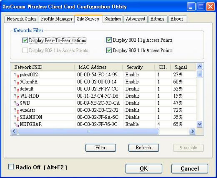
3.4 Site Survey Tab
Clicking on the Site Survey tab displays the Site Survey dialog
box:
This tab shows a list of all of the peer-to-peer and AP stations within range of the adapter.
3.4.1 Access Point Filter
This section lets you customize which sites are displayed in the Site Survey list window:
Ÿ Display Peer-To-Peer stations – checking this box displays all of the peer-to-peer stations within
range.
Ÿ Display 802.11a Access Points – checking this box displays all of the 802.11a APs within range.
Ÿ Display 802.11g Access Points – checking this box displays all of the 802.11g APs within range.
Ÿ Display 802.11b Access Points – checking this box displays all of the 802.11b APs within range.
36
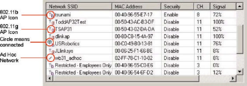
3.4.2 Site Survey List Window
This window reports information on the Ad Hoc or AP stations detected:
Ÿ Network SSID – the network SSID label; i.e., the Network Name. The Network Name is a text
string.
Ÿ MAC Address – the MAC address, a hardware address that uniquely identifies each node of a
network.
Ÿ Security – security enabled or disabled.
Ÿ CH. – displays the channel used by the detected device.
Ÿ Signal – displays the signal strength of the detected device as a percentage.
Ÿ Icons – the following icons may be displayed left of the Network SSID:
– an antenna icon with a superscript b indicates an 802.11b AP.
– an antenna icon with a supers cript g indicates an 802.11g AP.
– a circle around the antenna icon means the adapter is connected to this network.
– a slash icon indicate an Ad Hoc network.
37
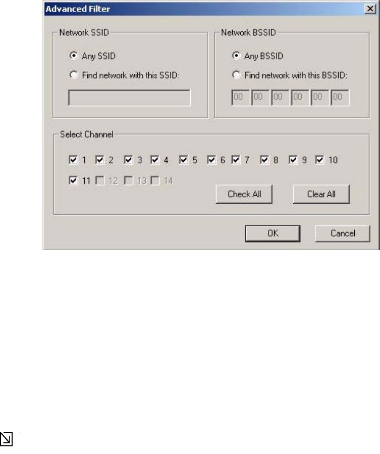
3.4.3 Filter Button
Clicking the Filter button displays the Advanced Filter dialog
box:
3.4.3.1 Network SSID
. • Any SSID – if selected, any SSID is used.
. • Find network with this SSID – if selected, the utility searches for the specified SSID.
3.4.3.2 Network BSSID
. • Any SSID – if selected, any BSSID is used.
. • Find network with this BSSID – if selected, the utility searches for the specified BSSID.
3.4.3.3 Select Channel
Allows channels to be checked individually or all checked or all cleared.
Note
Only the checked channels will be used in the site
survey.
3.4.4 Refresh Button
Clicking the Refresh button requests a survey of the wireless networks in the
area.
38
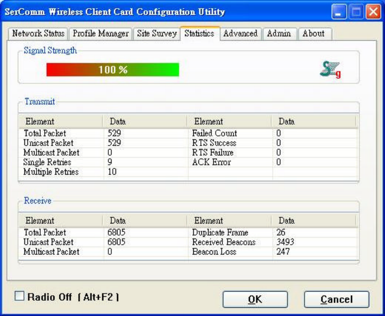
3.5 Statistics Tab
Clicking on the Statistics tab displays the statistics of the current connect session:
3.5.1 Signal Strength
The color-coded Signal Strength bar displays the signal strength of the last packet received by the adapter.
Signal strength is reported as a percentage. A signal in the red indicates a bad connection. A signal in the
green indicates a good connection.
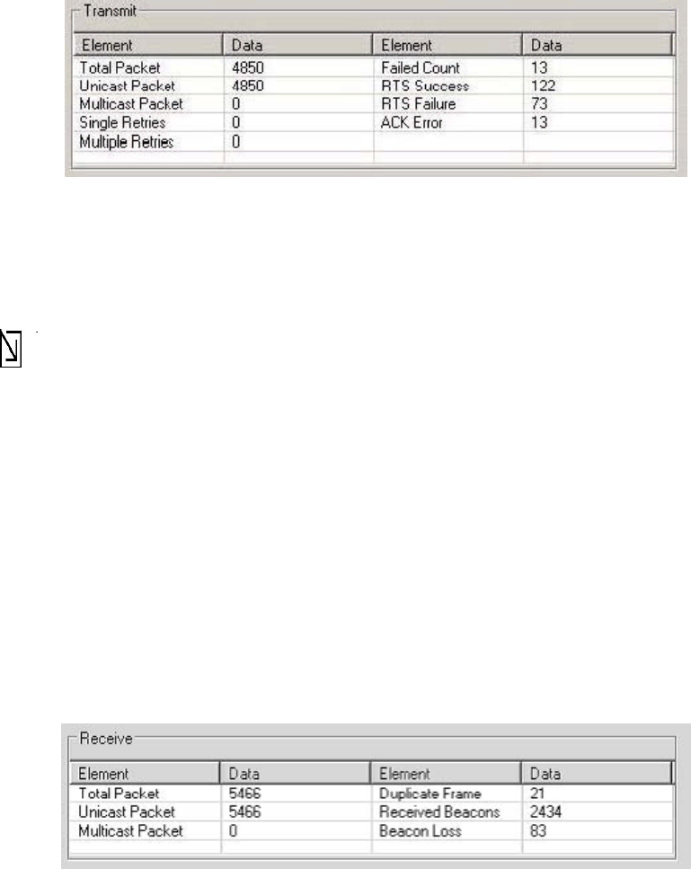
3.5.2 Transmit Window
The Transmit window displays the information on the packets
sent:
39
Ÿ Total Packet – reports the total number of packets transmitted.
Ÿ Unicast Packet – reports the number of packets transmitted by the adapter that were destine for
a single network node.
Ÿ Multicast Packet – reports the number of packets transmitted by the adapter that were destine
for more than one network node.
Ÿ Single Retries – reports the number of packets that require one retry before the adapter
received an acknowledgement.
Note
After the adapter sends a packet, it waits for an acknowledge from the receiving radio to confirm that
the packet was successfully received. If the acknowledge is not received within a specified period of
time, the adapter retransmits the packet.
Ÿ Multiple Retries – reports the number of packets that require more than one retry before the
adapter received an acknowledgement.
Ÿ Failed Count – reports the number of packets that were not successfully transmitted because
the adapter did not received an acknowledge within the specified period of time.
Ÿ RTS Success – reports the number of RTS attempts that were successful.
Ÿ RTS Failure – reports the number of RTS attempts that were not successful.
Ÿ ACK Error – reports the number of unicast transmit attempts for which no ACK was received.
3.5.3 Receive Window
The Receive window displays the information on the packets received:
Ÿ Total Packet – Reports the total number of packets received.
Ÿ Unicast Packet – Reports the number of packets received by the adapter that were destined for
a single network node.
Ÿ Multicast Packet – Reports the number of packets received by the adapter that were destined
for more than one network node.
Ÿ Duplicate Frame – Reports the number of duplicate frames received.
Ÿ Received Beacons — Reports the number of beacons received after association is established.
Ÿ Beacon Loss — Reports the number of missing beacons after association is established.
40
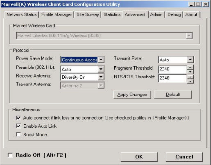
3.6 Advanced Tab
Clicking on the Advanced tab displays the Advanced dialog box.
This tab displays the advanced parameters available. The major components of this tab are described in the
sections which follow.
3.6.1 CB801M Wireless Card
This window reports the type of CB801M WLAN adapter installed.
41
3.6.2 Protocol
This section of the Advanced tab sets the Protocol options:
Ÿ Power Save Mode – Sets the power mode, either:
– Continuous Access
– Max Power Save
Ÿ Preamble (802.11b) – Set the radio preamble (takes effect only when attaching to 802.11b networks):
– Auto
– Long
Ÿ Transmit Antenna – Transmit Antenna mode is set to Antenna 2
Ÿ Receive Antenna – sets the Receive Antenna mode, either:
– Diversity On
– Diversity Off
Ÿ Transmit Rate – the range of the data rate depends on the type of AP that the client card is connected
to. The default setting is Auto Select.
Ÿ Fragment Threshold – sets the fragmentation threshold (i.e., the size that packets are fragmented into
for transmission). The default setting is 2346.
Ÿ RTS/CTS Threshold – set the packet size at which the AP issues a RTS (or CTS) frame before
sending the packet. The default setting is 2346.
The Apply Changes or Default buttons configure the options according to the changes entered or apply the
default values.
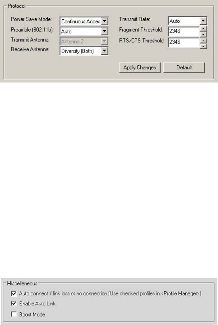
3.6.3 Miscellaneous
Ÿ Auto connect if link loss or no connection (Use checked profiles in <Profile Manager>) –
Unchecking this box disables the auto-configuration feature. Whenever there is a link loss,
auto-configuration tries to establish a connection according to the checked profiles in the Profile
Manager.
Ÿ Enable Auto Link – This option allows the user to enable/disable the Auto Link feature (see “Auto
Link” )
Ÿ Boost Mode – Check the Boost Mode box for performance enhancement.
42
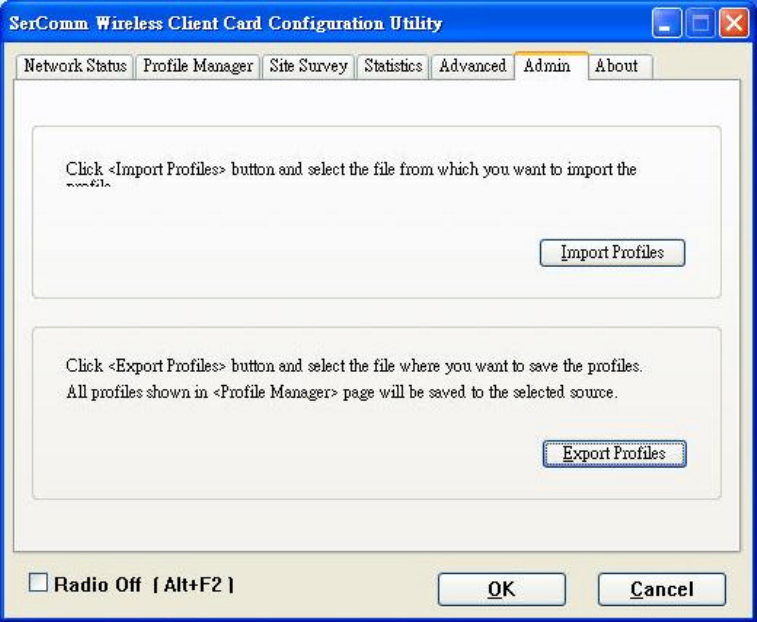
3.7 Admin Tab
Clicking the Admin tab displays the Admin dialog box. This tab allows you to import and export profiles.
3.7.1 Import Profiles
To import a profile:
1. Click the Import Profiles button.
2. Select the path and filename of the profile.
3. Click Open.
3.7.2 Export Profiles
To export a profile:
1. Click the Export Profiles button.
2. Select the path and filename of the profile.
3. Click Save .
43
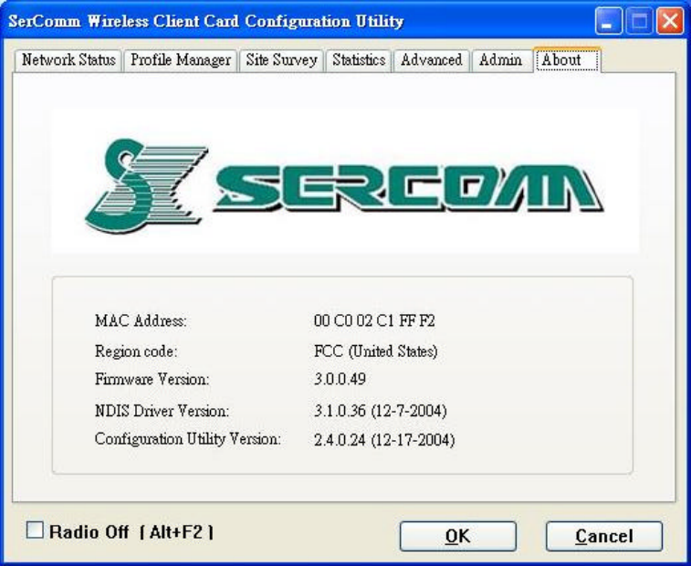
3.8 About Tab
Clicking on the About tab displays the About dialog box, as shown in the following
example.
44
3.9 Auto Link
TBD

45
Appendix A Specifications
Chipset: Marvell 88W8335
RF Chip: Marvell 88W8010
Bus Type: CardBus
54, 48, 36, 24, 18, 12, 9, and 6 Mbps (802.11g)
Data Rates : 11, 5.5, 2, 1 Mbps (802.11b)
Frequency Band : 2.4GHz to 2.462GHz
Wireless Medium : DSSS and OFDM
Media Access Protocol:
CSMA/CA
Operating Channels: 1-14(FCC:1 -11、ETSI:1 -13、Japan:1-13 )
Operating Range: • Indoors: Up to 328 ft (100 meters)
• Outdoors: Up to 1312 ft (400 meters)
Receive Sensitivity :
54 Mbps: -70 dBm
48 Mbps: -72 dBm
36 Mbps: -77 dBm
24 Mbps: -80 dBm
18 Mbps: -82 dBm
12 Mb ps: -85 dBm
9 Mbps: -86 dBm
802.11g
6 Mbps: -88 dBm
11 Mbps: -86 dBm
5.5 Mbps: -89 dBm
2 Mbps: -91 dBm
802.11b
1 Mbps: -91 dBm
Wireless Medium: DSSS (Direct Sequence Spread Spectrum)
Media Access Protocol:
CSMA/CA
Transmit Power:
802.11g:
14±2 dBm
802.11b:
16±2 dBm
Security : 64/128-bit WEP
WPA—Wi-Fi Protected Access
Standards Conformance:
WPA certified, IEEE 802.11g, IEEE 802.11b
EMI: FCC, CE
Environmental Range:

46
Operating temperature:
0o to 40oC (32o to 104oF)
Operating humid
ity:
0 to 90% non-condensing
System Requirements Notebook PC must be running Windows 98SE/ME/XP/ 2000