Sercomm DRG600WIFI Wireless Router User Manual DRG600 Wifi User Guide
Sercomm Corporation Wireless Router DRG600 Wifi User Guide
UserManual.wiki
>
Sercomm
>
DRG600WIFI User Manual
User manual
Navigation menu
Upload a User Manual
Namespaces
Wiki Guide
HTML
PDF
Info
Views
User Manual
Discussion / Help
Navigation


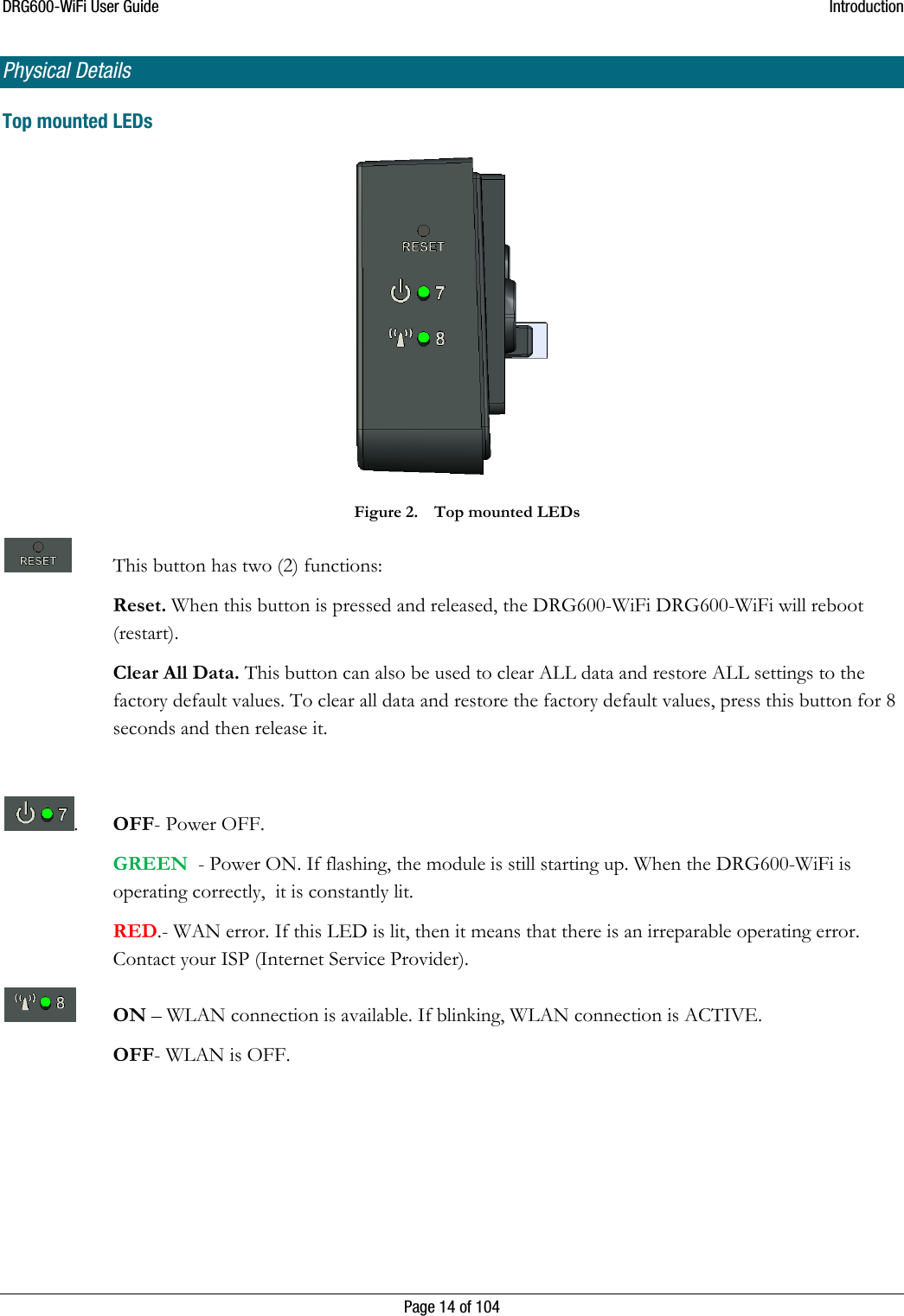
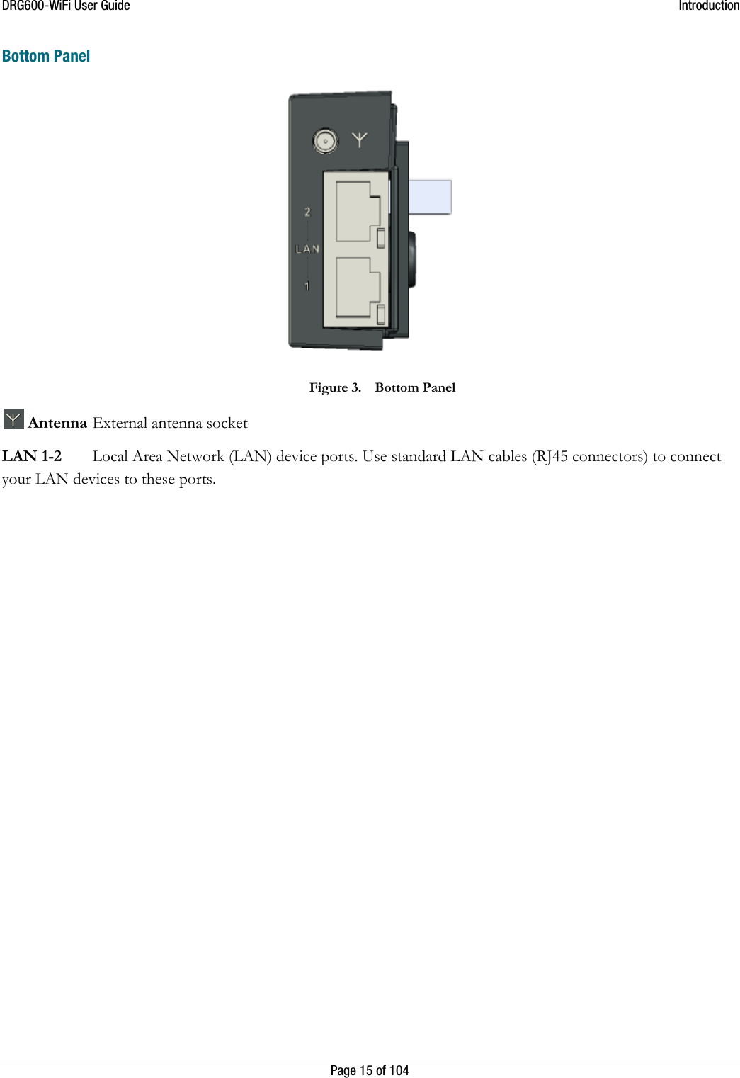
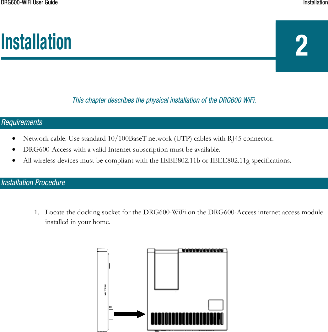
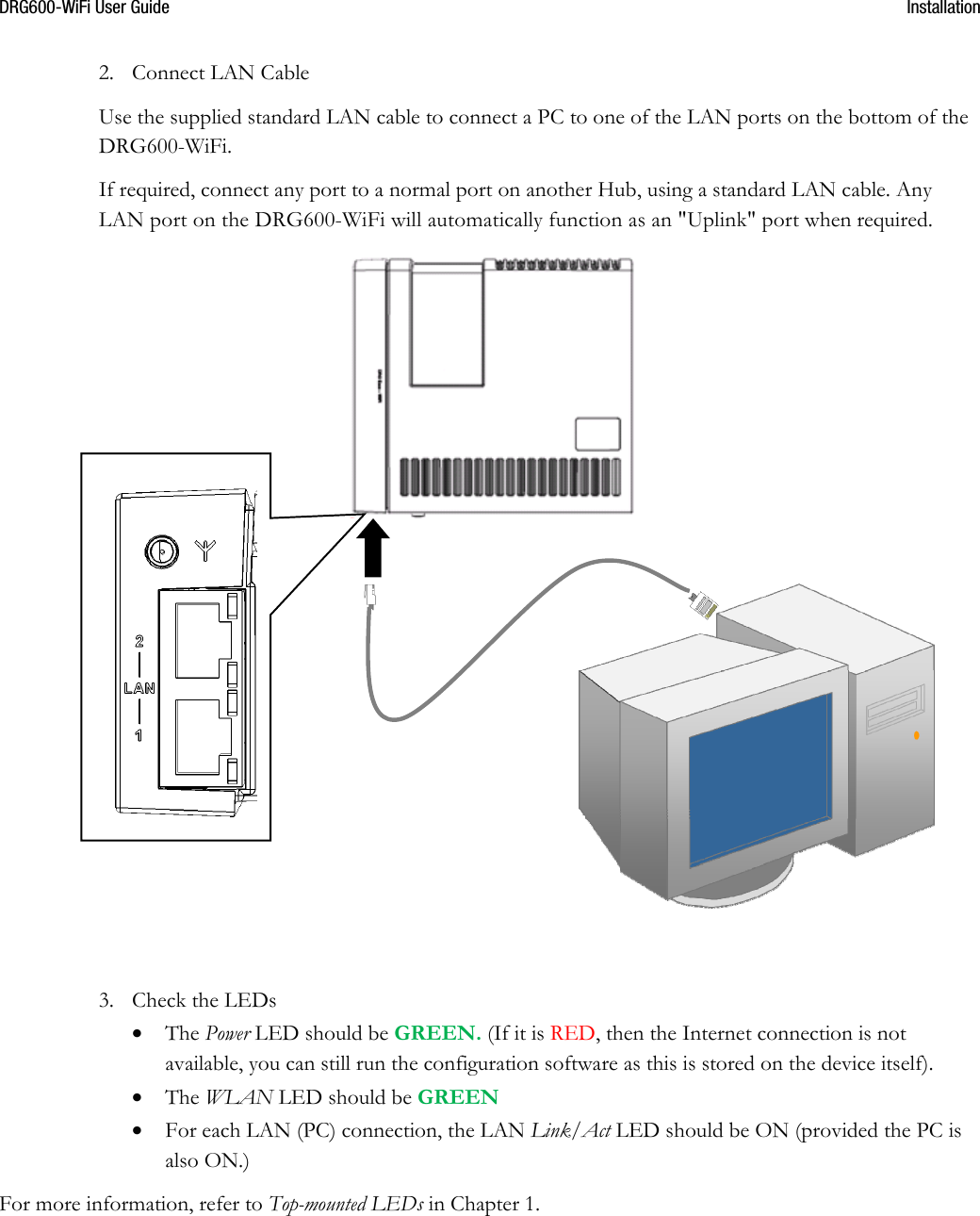
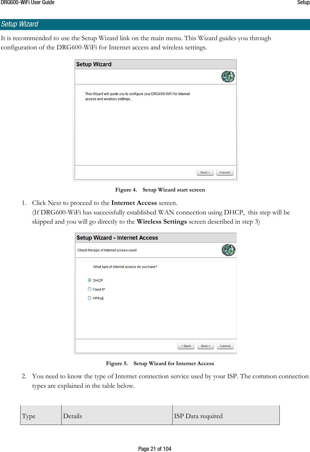
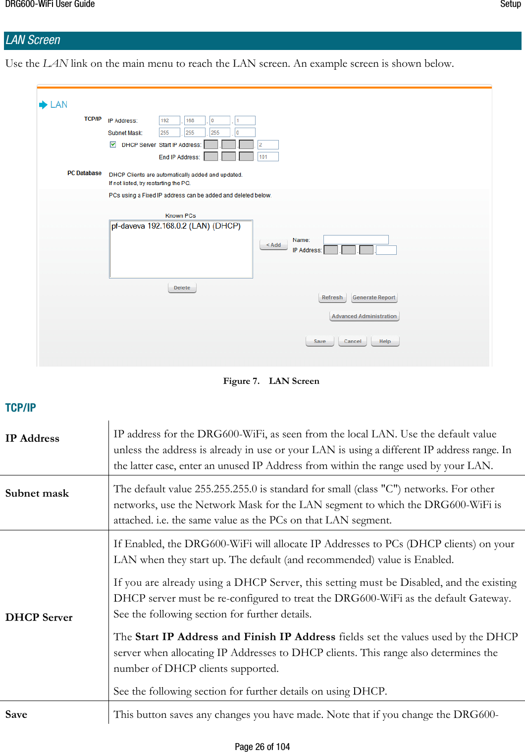
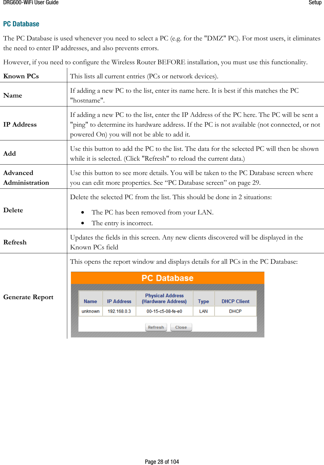
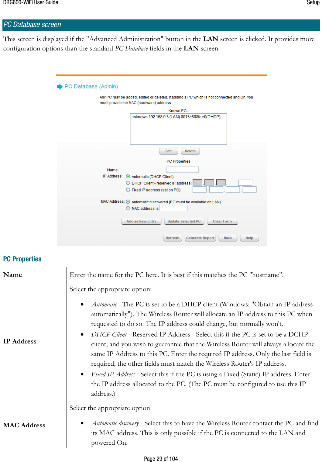
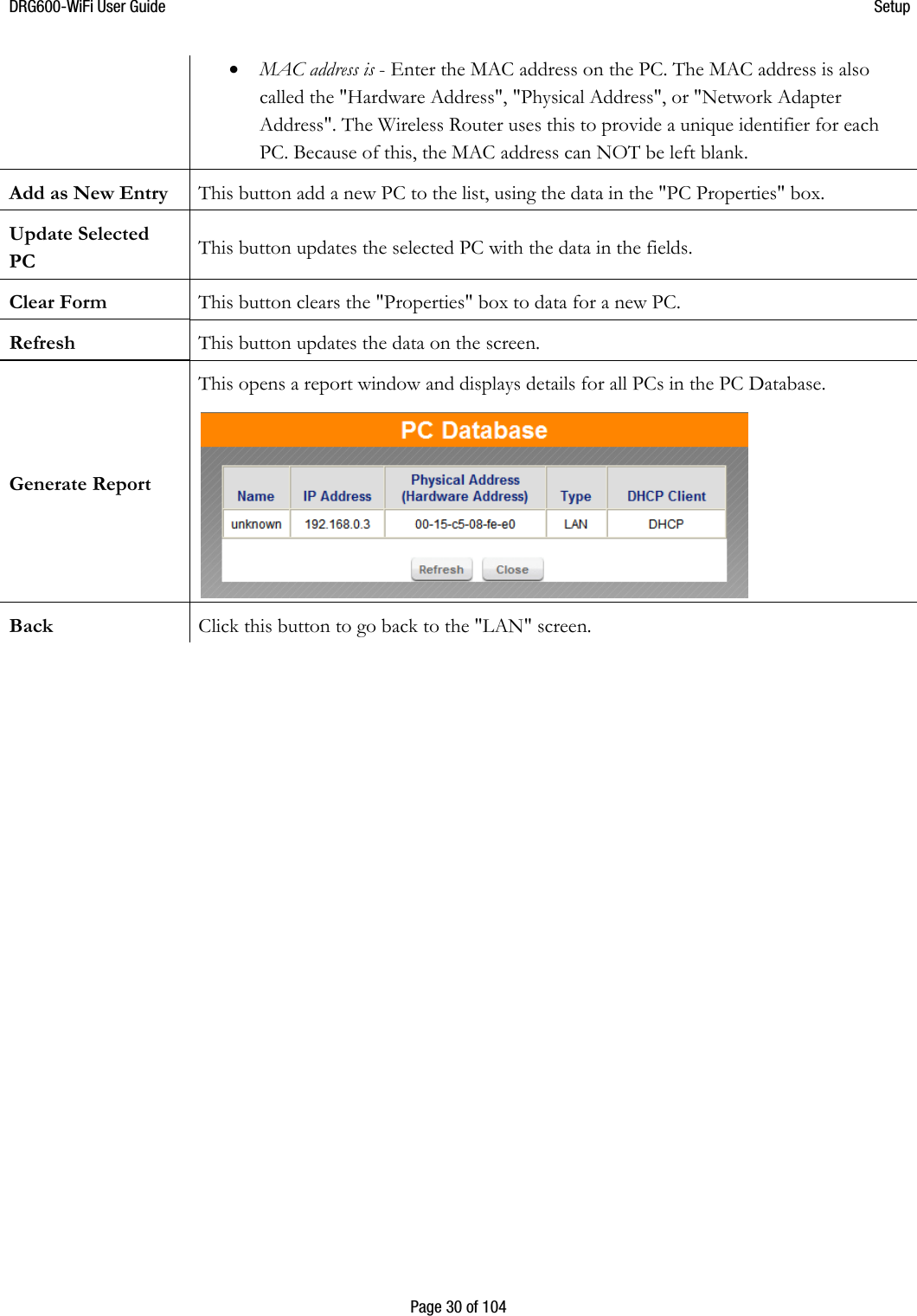
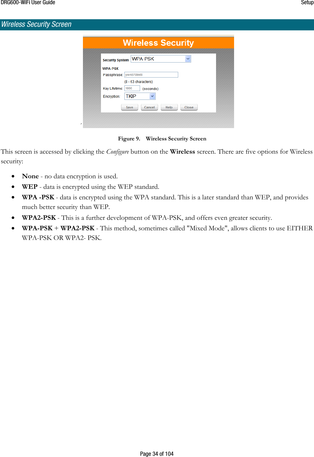
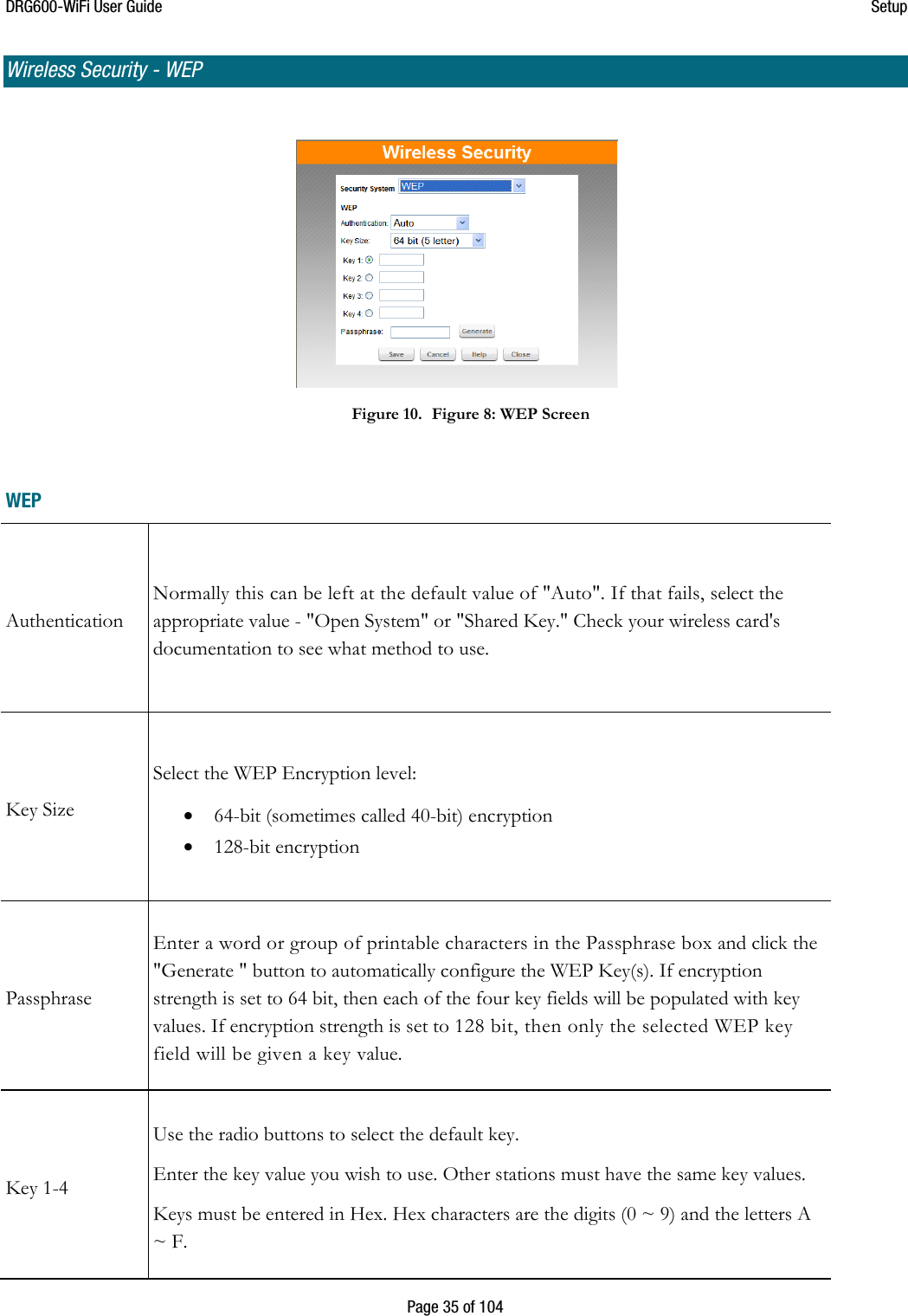
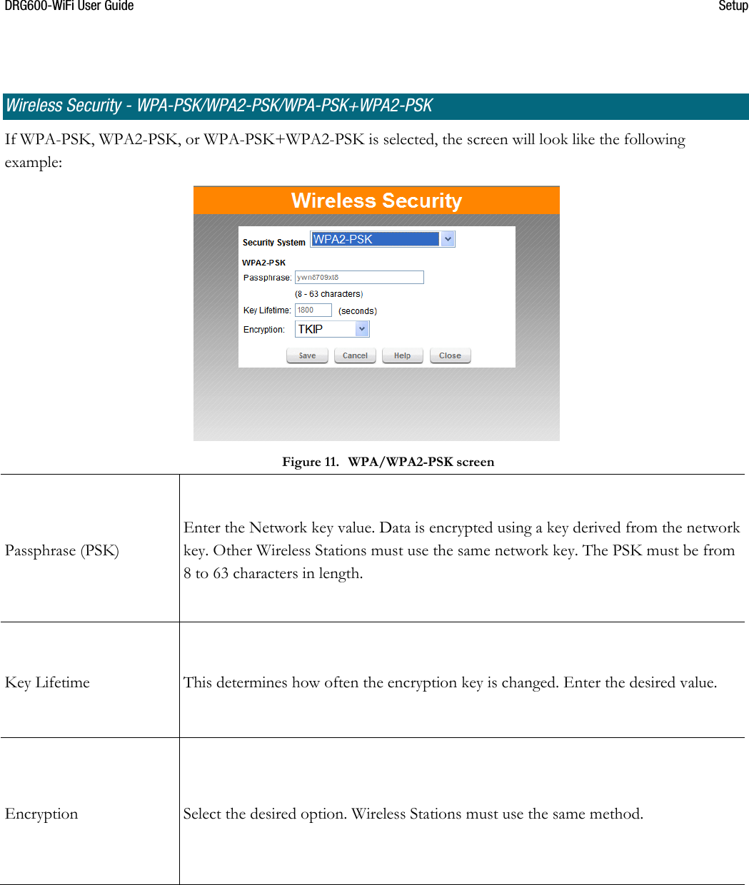
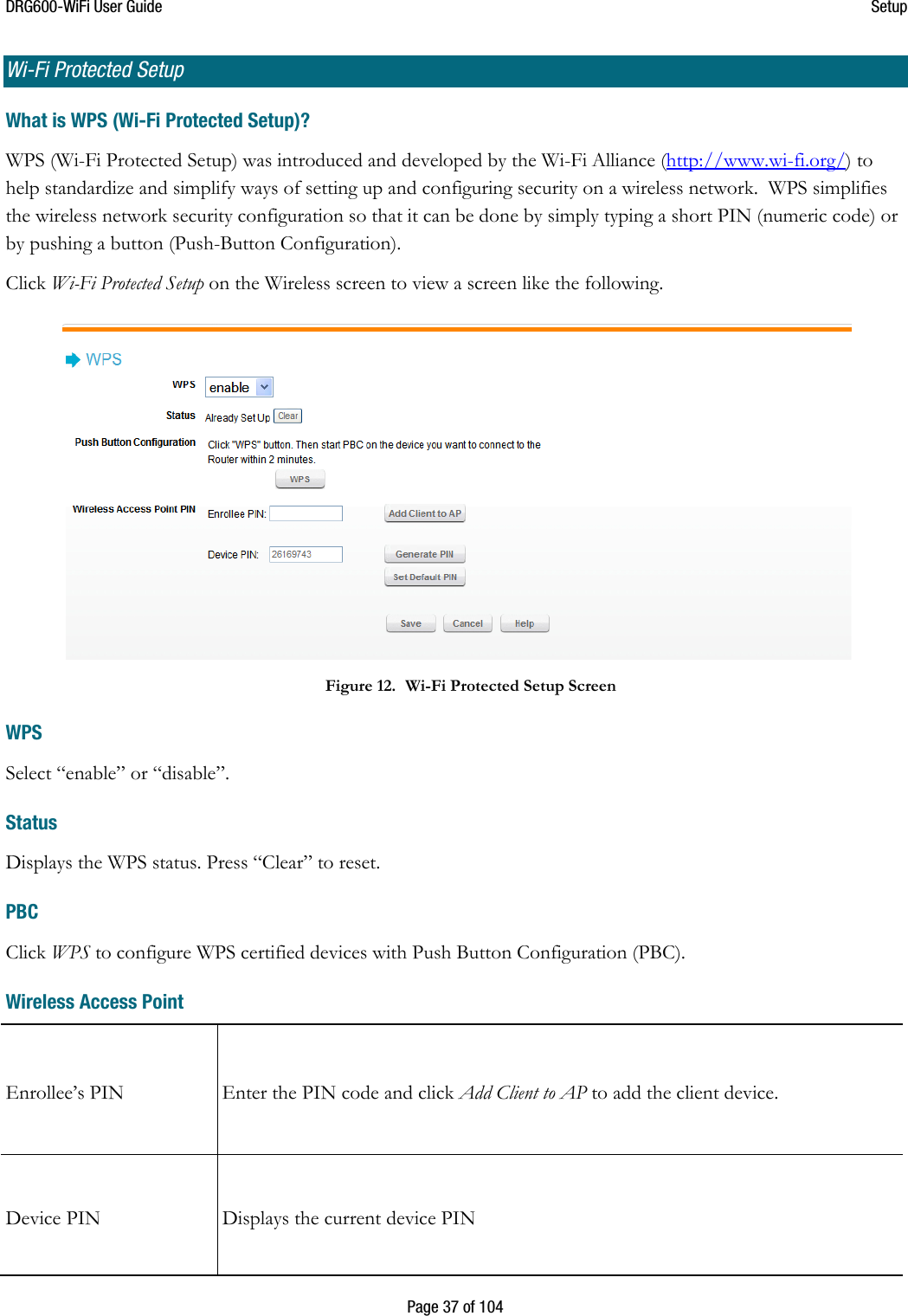

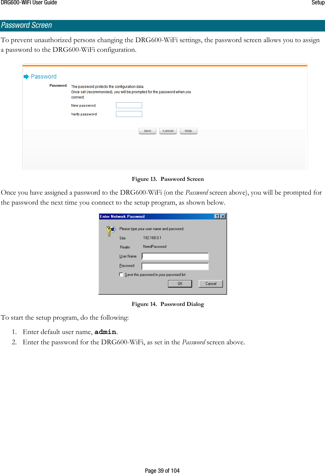
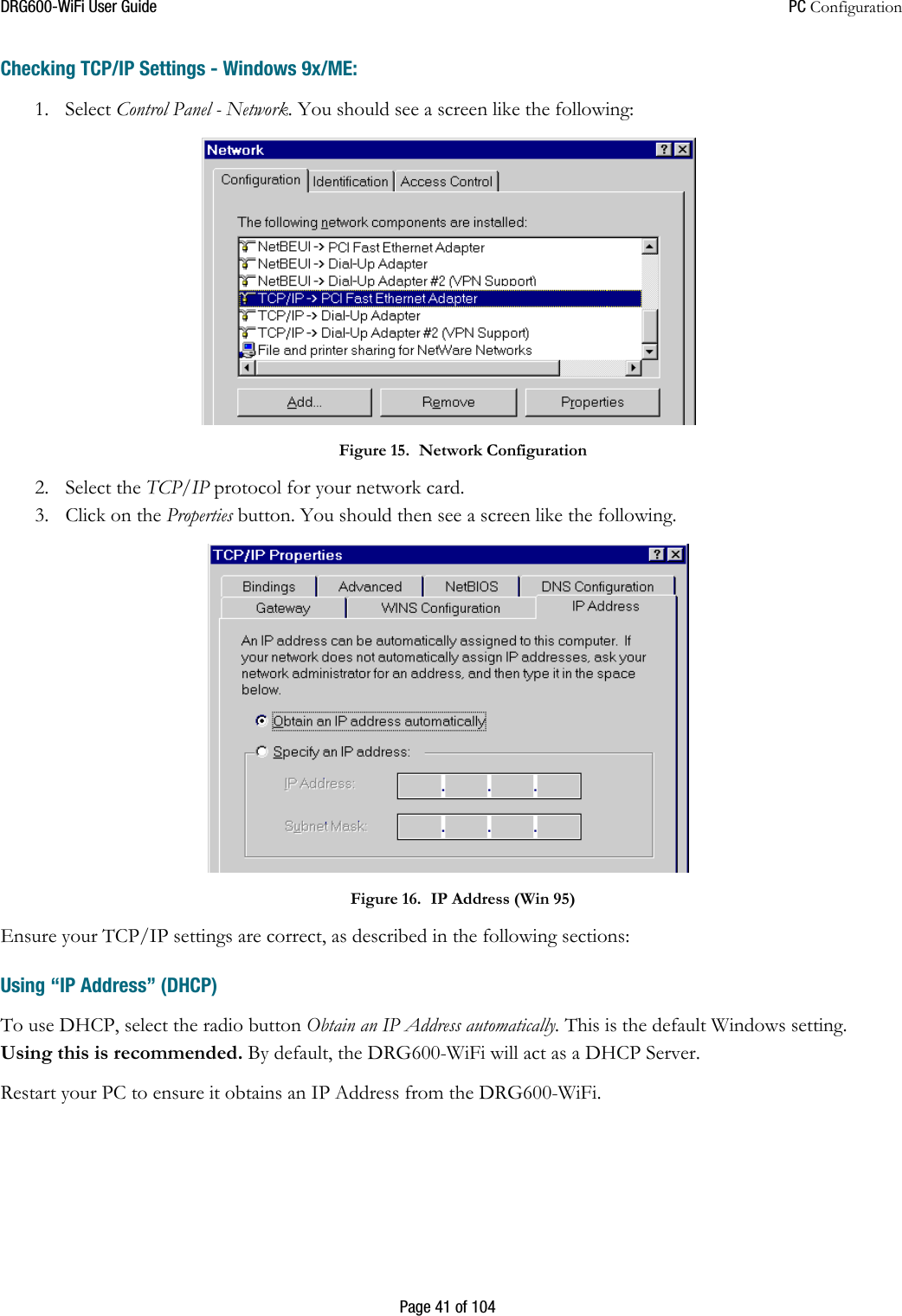
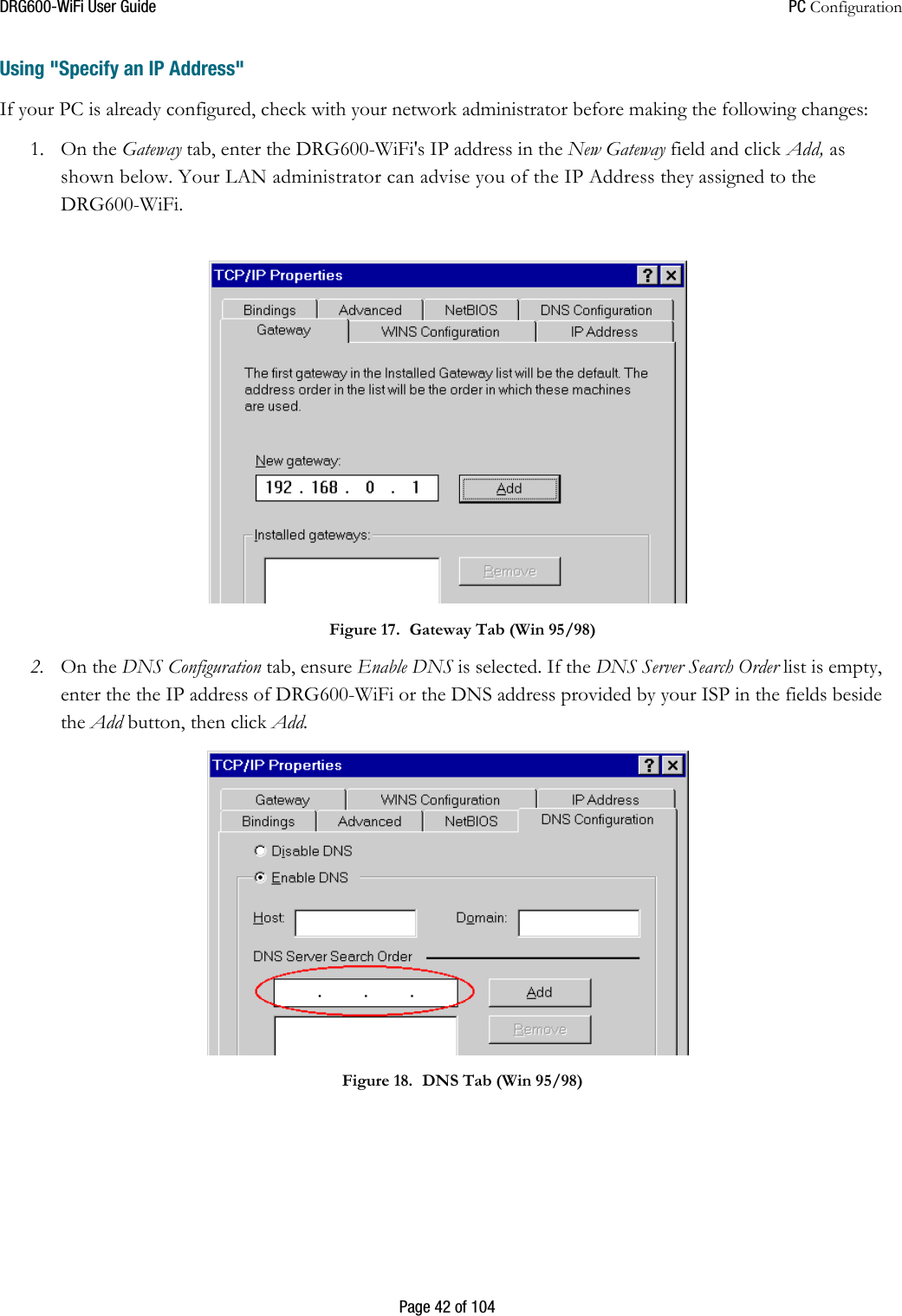
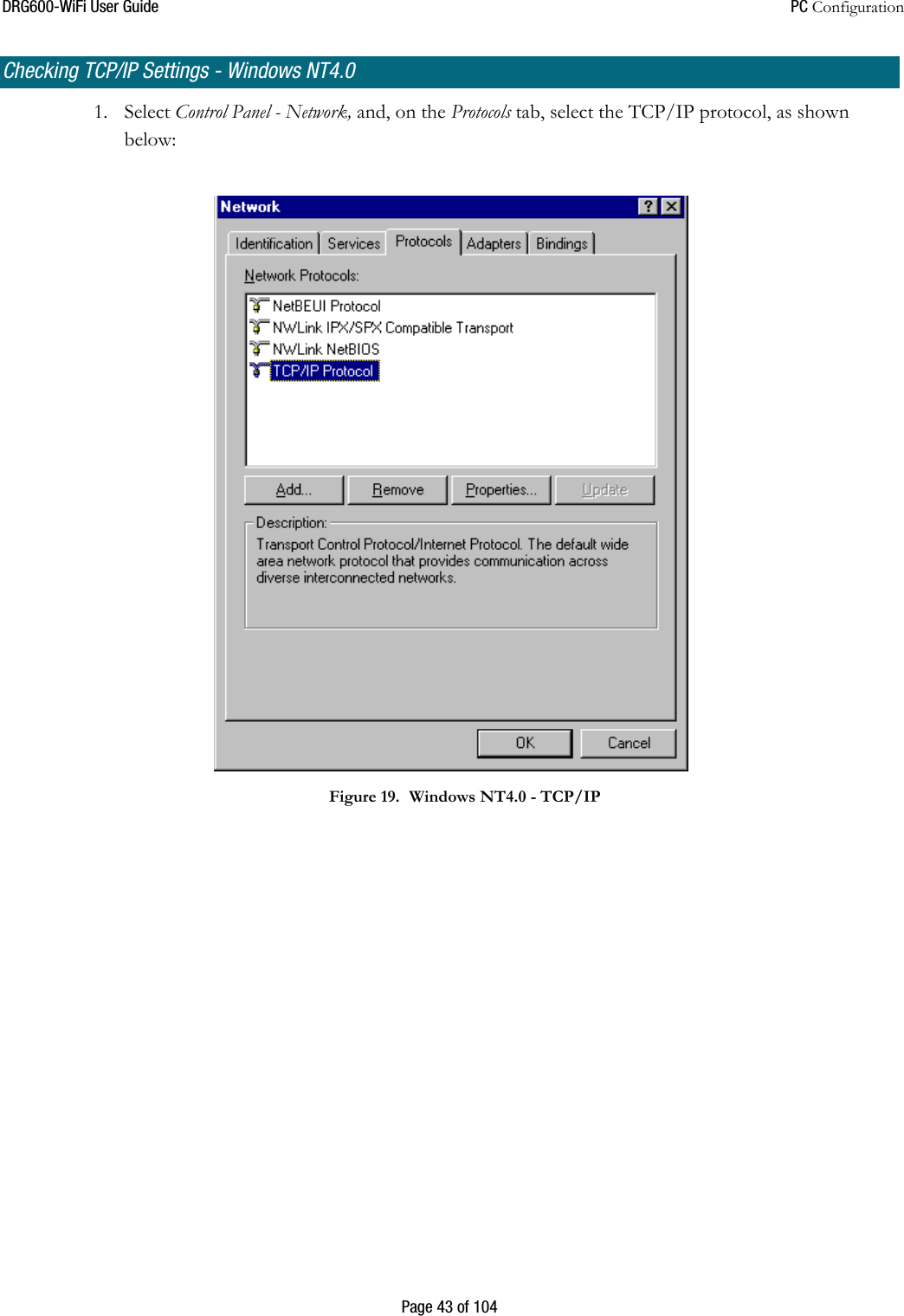
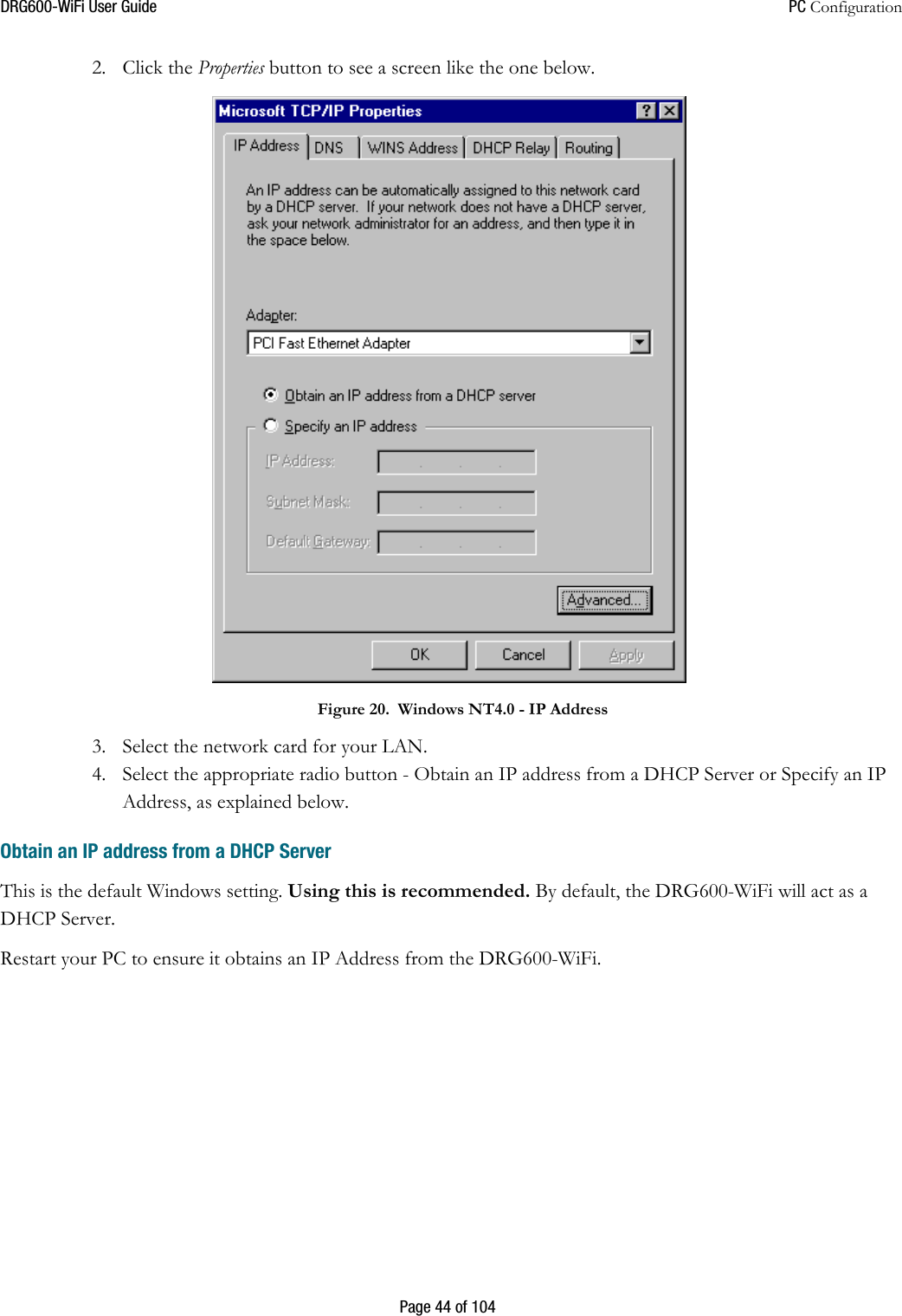
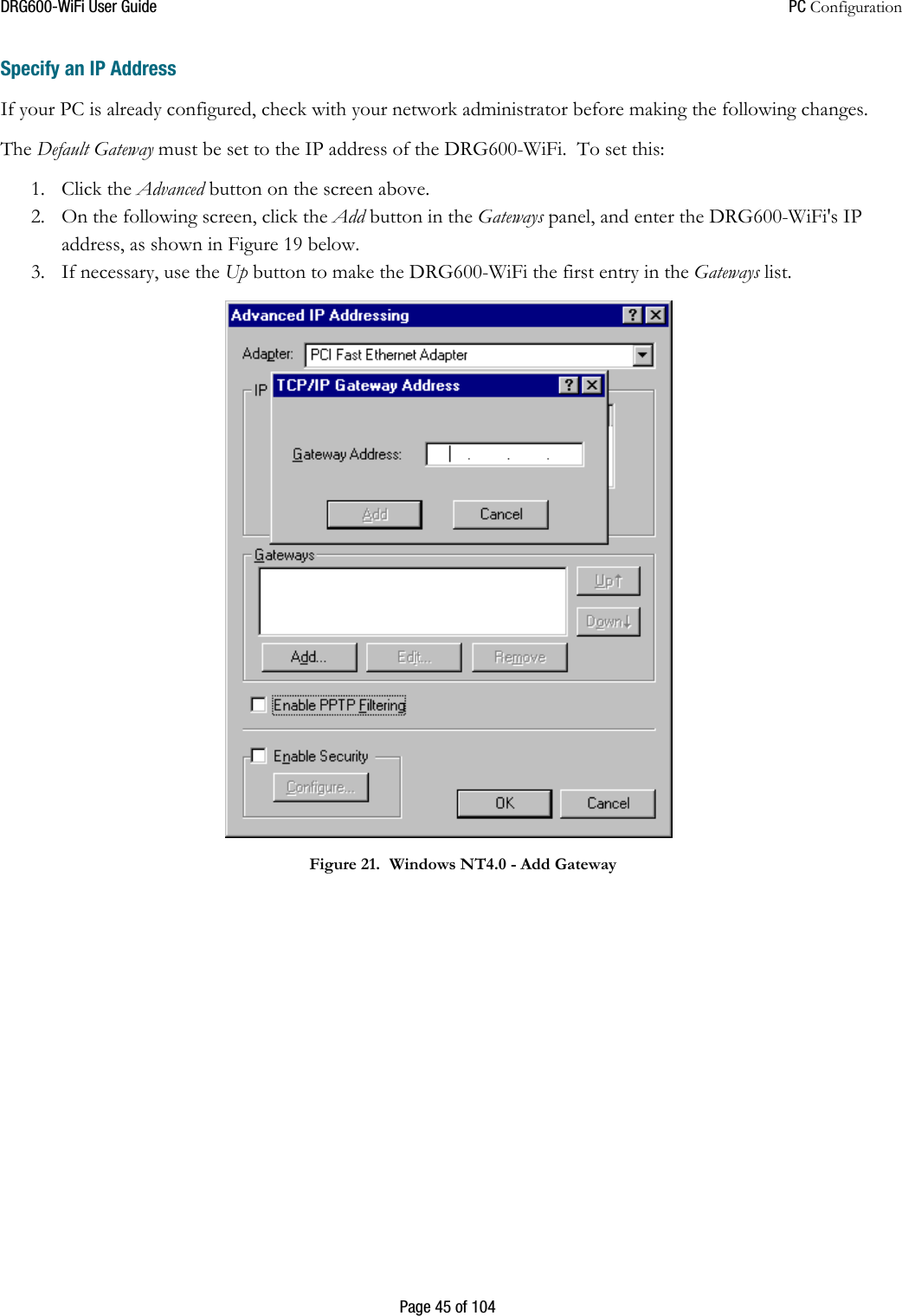
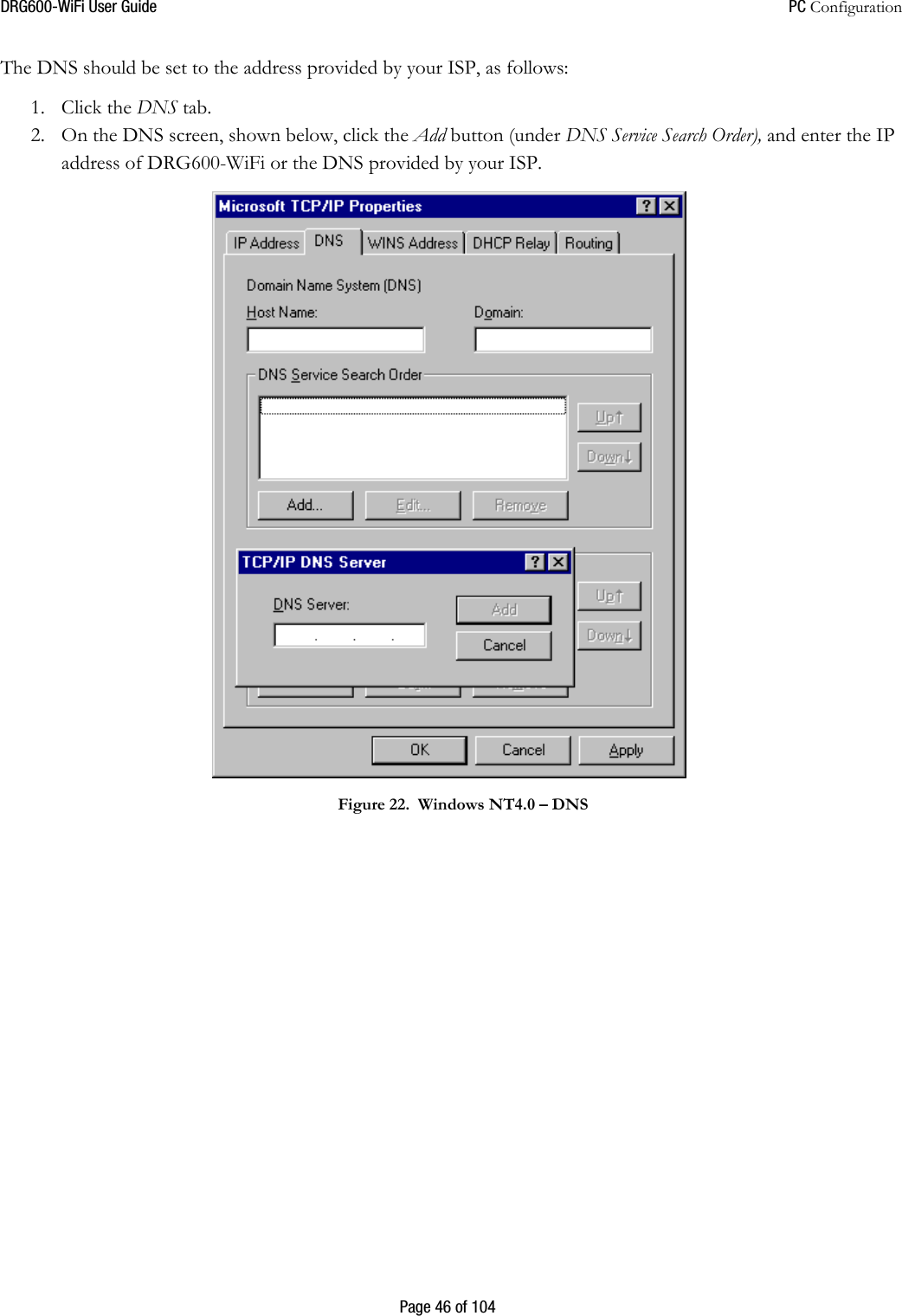
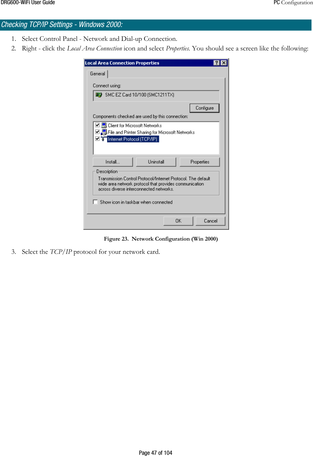
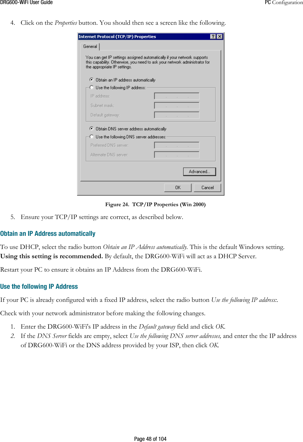
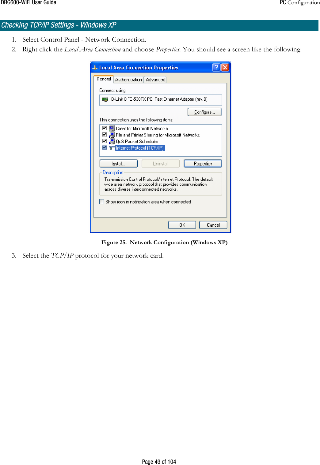
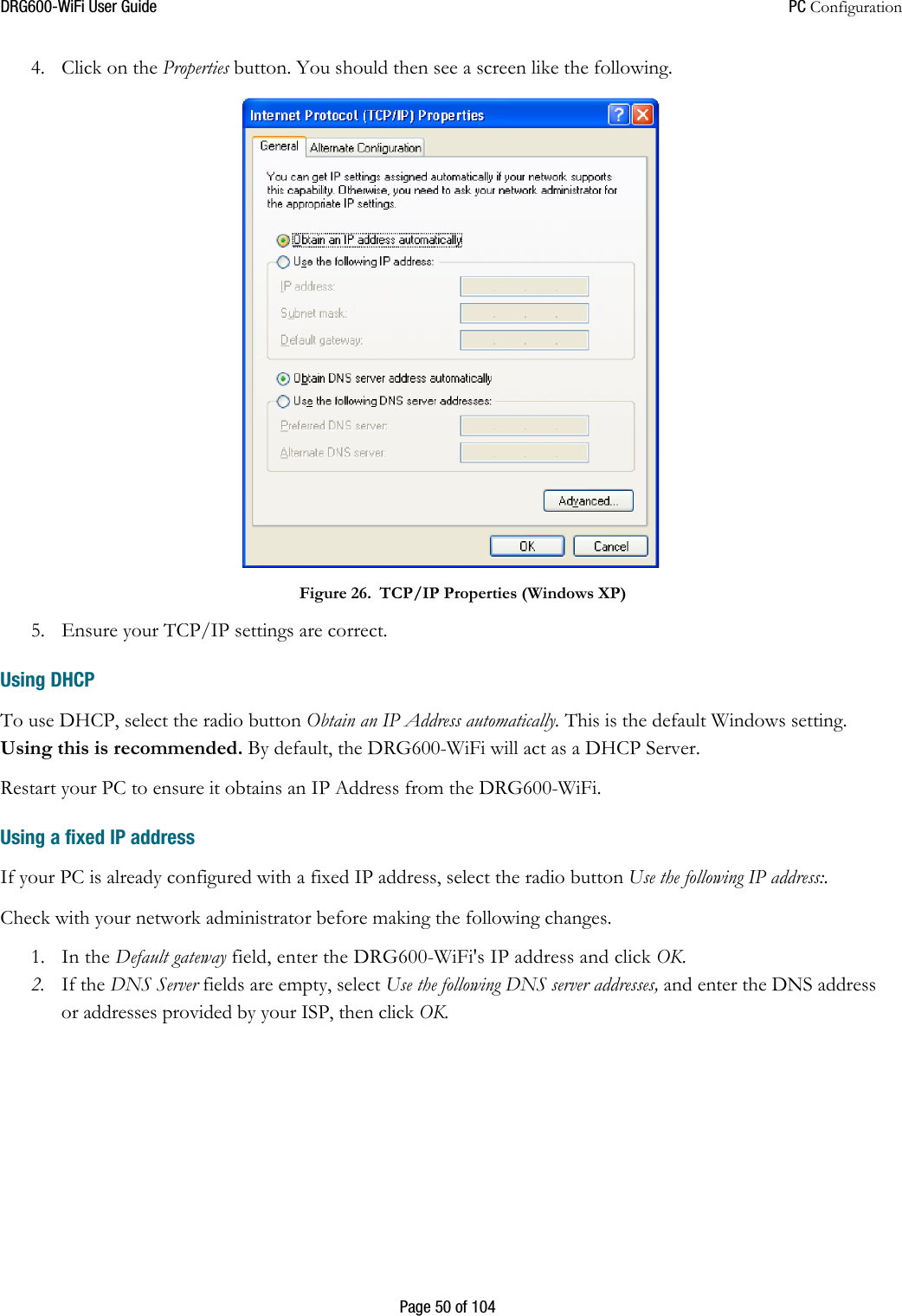
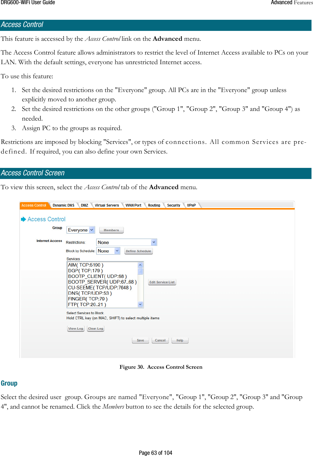
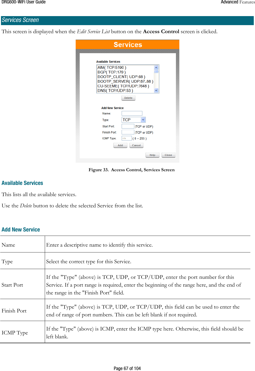
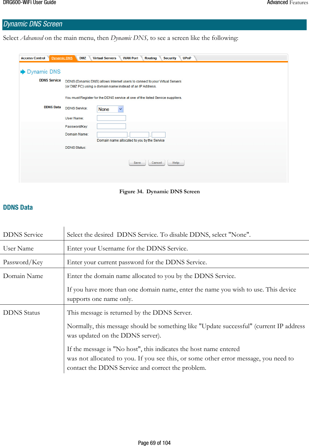
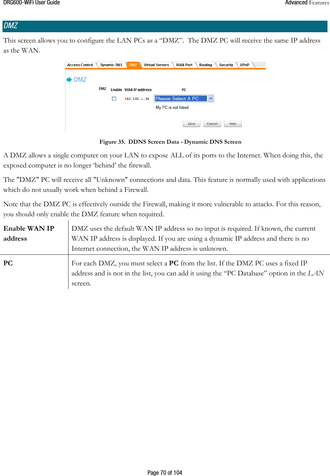
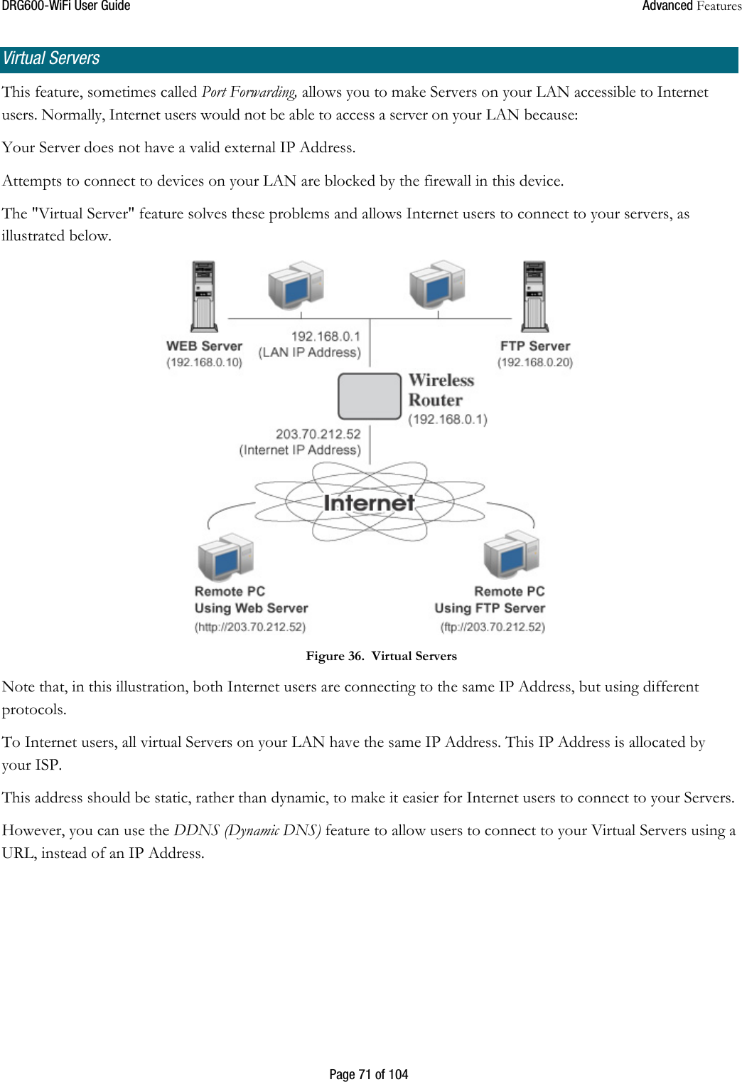
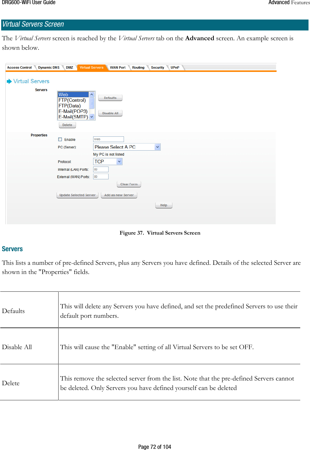
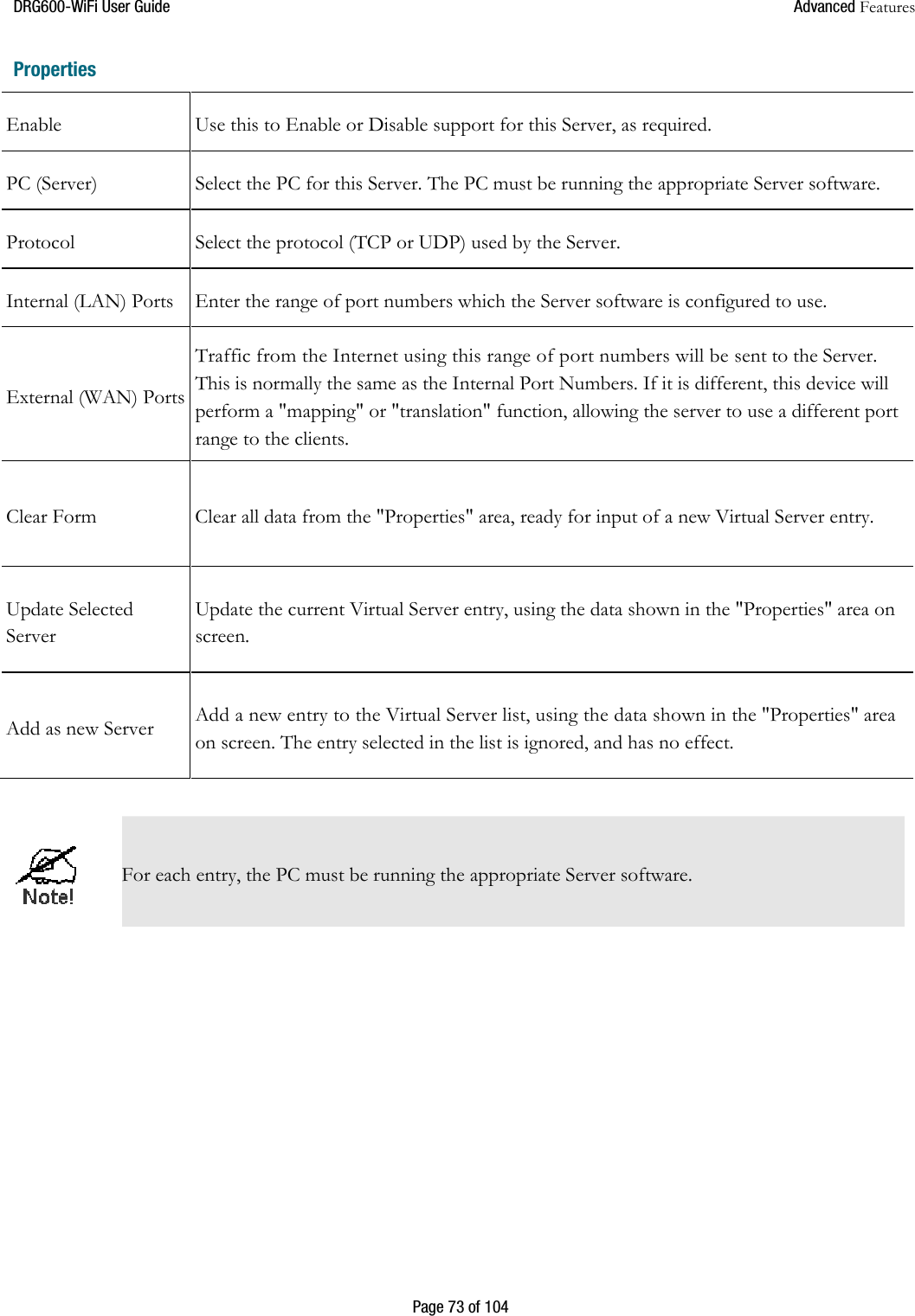
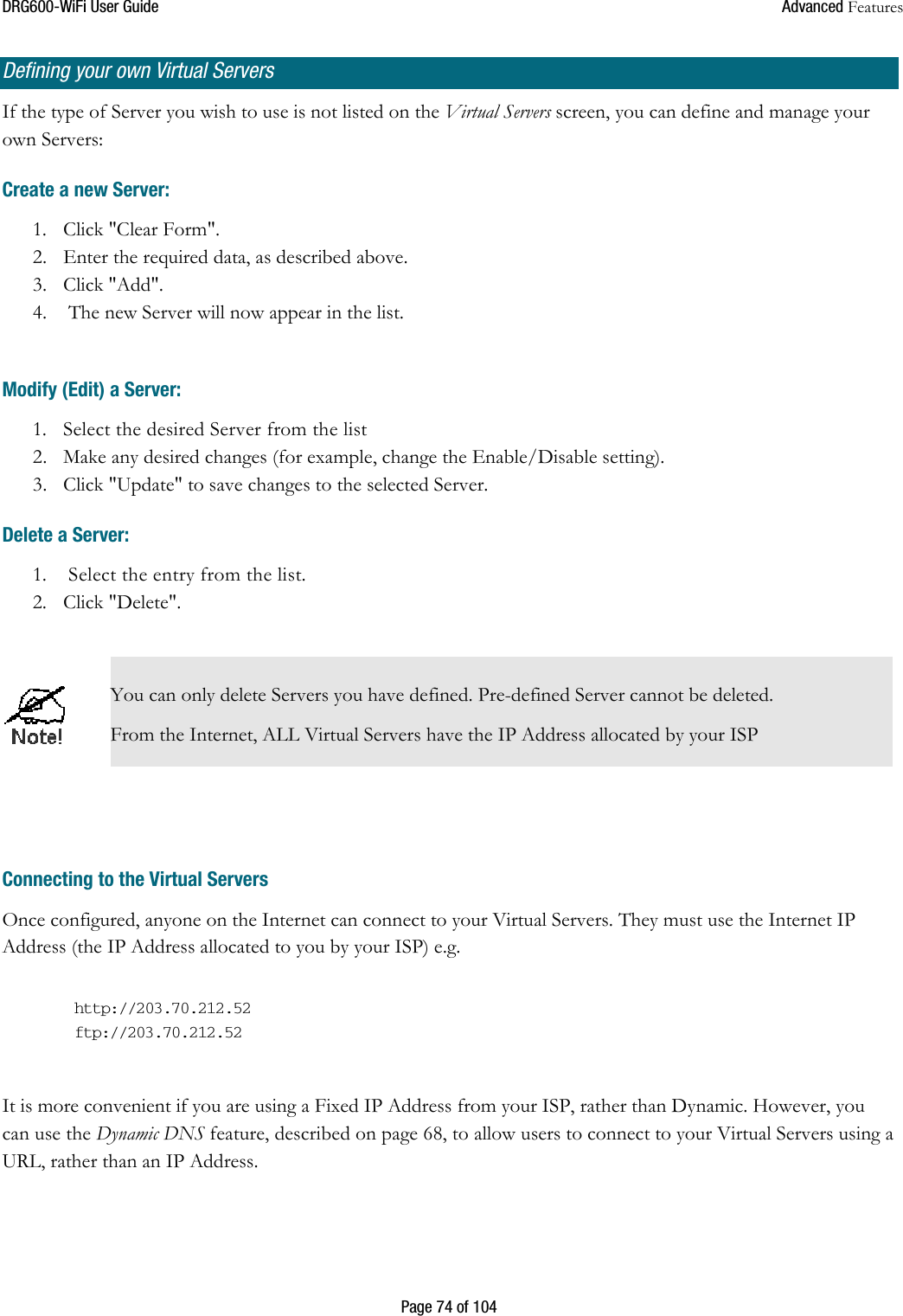

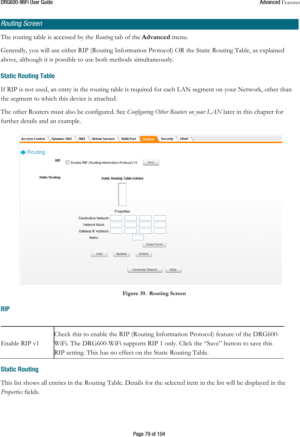
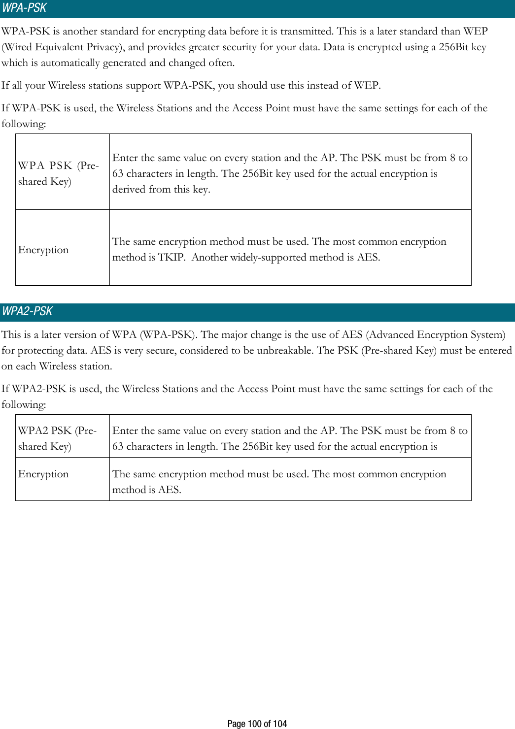
![DRG600WiFi User Guide Advanced Features Page 78 of 104 Routing • If you don't have other Routers or Gateways on your LAN, you can ignore the "Routing" page completely. • If the DRG600-WiFi is only acting as a Gateway for the local LAN segment, ignore the "Routing" page even if your LAN has other Routers. • If your LAN has a standard Router on your LAN, and the DRG600-WiFi is to act as a Gateway for all LAN segments, enable RIP (Routing Information Protocol) and ignore the Static Routing table. • If your LAN has other Gateways and Routers, and you wish to control which LAN segments use each Gateway, do NOT enable RIP (Routing Information Protocol). Configure the Static Routing table instead. (You also need to configure the other Routers.) • If you are using Windows 2000 Data center Server as a software Router, you must enable RIP on the Wireless Router, and ensure the following Windows 2000 settings are correct: o Open Routing and Remote Access o In the console tree, select Routing and Remote Access , [server name], IP Routing, RIP o In the "Details" pane, right-click the interface you want to configure for RIP version 2, and then click "Properties". o On the "General" tab, set Outgoing packet protocol to "RIP version 2 broadcast", and Incoming packet protocol to "RIP version 1 and 2".](https://usermanual.wiki/Sercomm/DRG600WIFI/User-Guide-971958-Page-78.png)