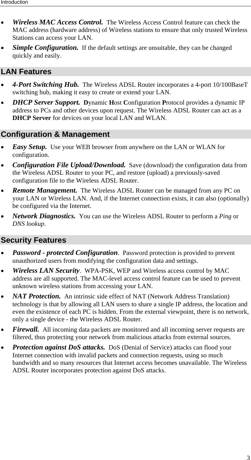
Sercomm IP806GAV3 ADSL Wireless Router with 4-Port Switch User Manual Wireless ADSL VPN Router
Sercomm Corporation ADSL Wireless Router with 4-Port Switch Wireless ADSL VPN Router
UserManual.wiki
>
Sercomm
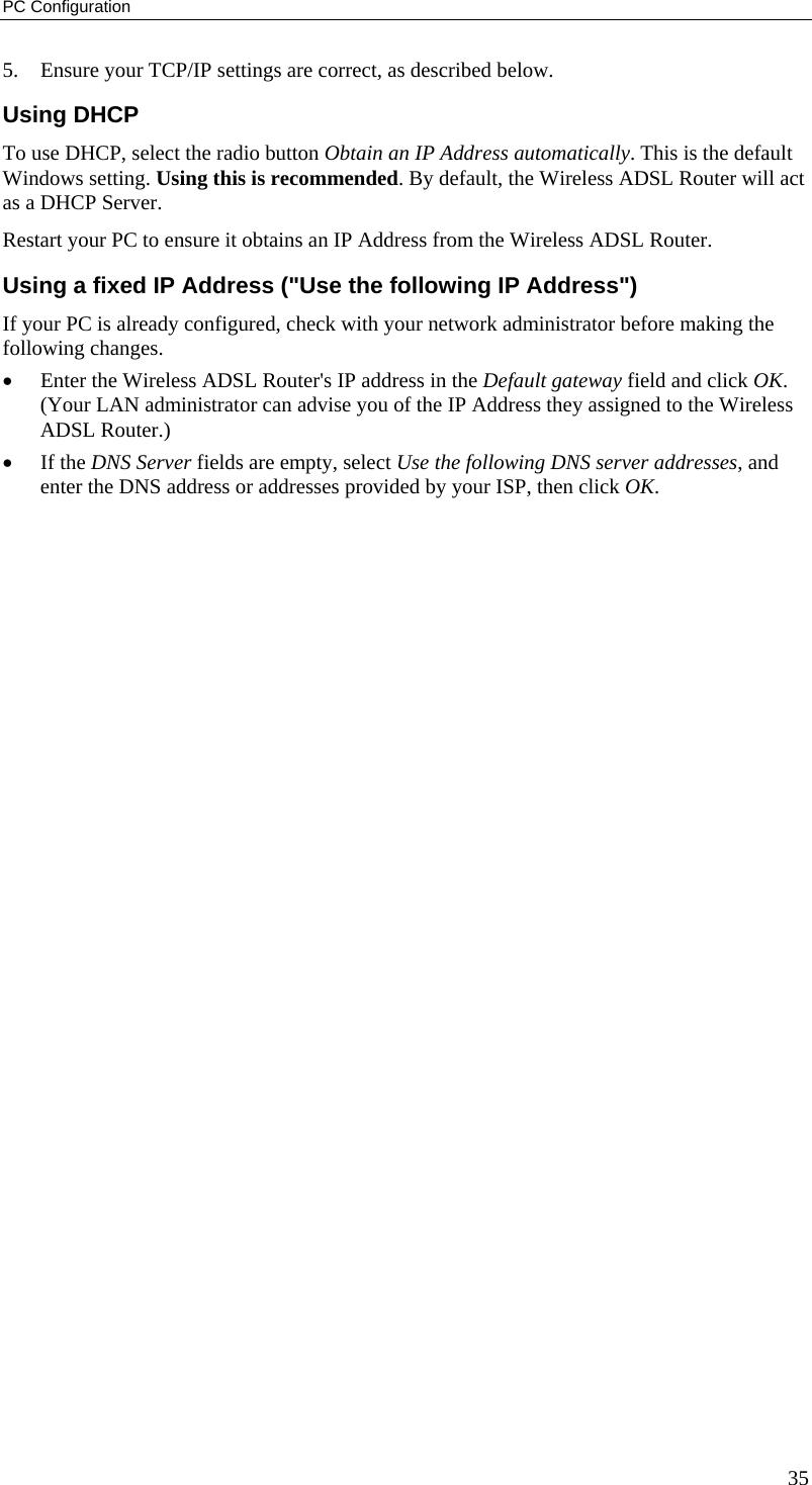
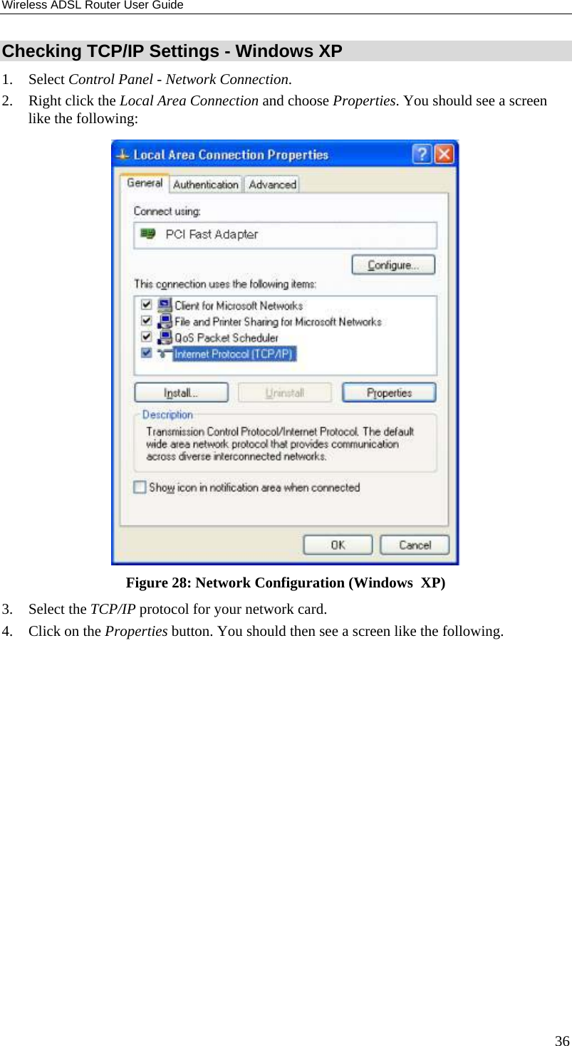
>
IP806GAV3 User Manual
Users manual
Navigation menu
Upload a User Manual
Namespaces
Wiki Guide
HTML
PDF
Info
Views
User Manual
Discussion / Help
Navigation
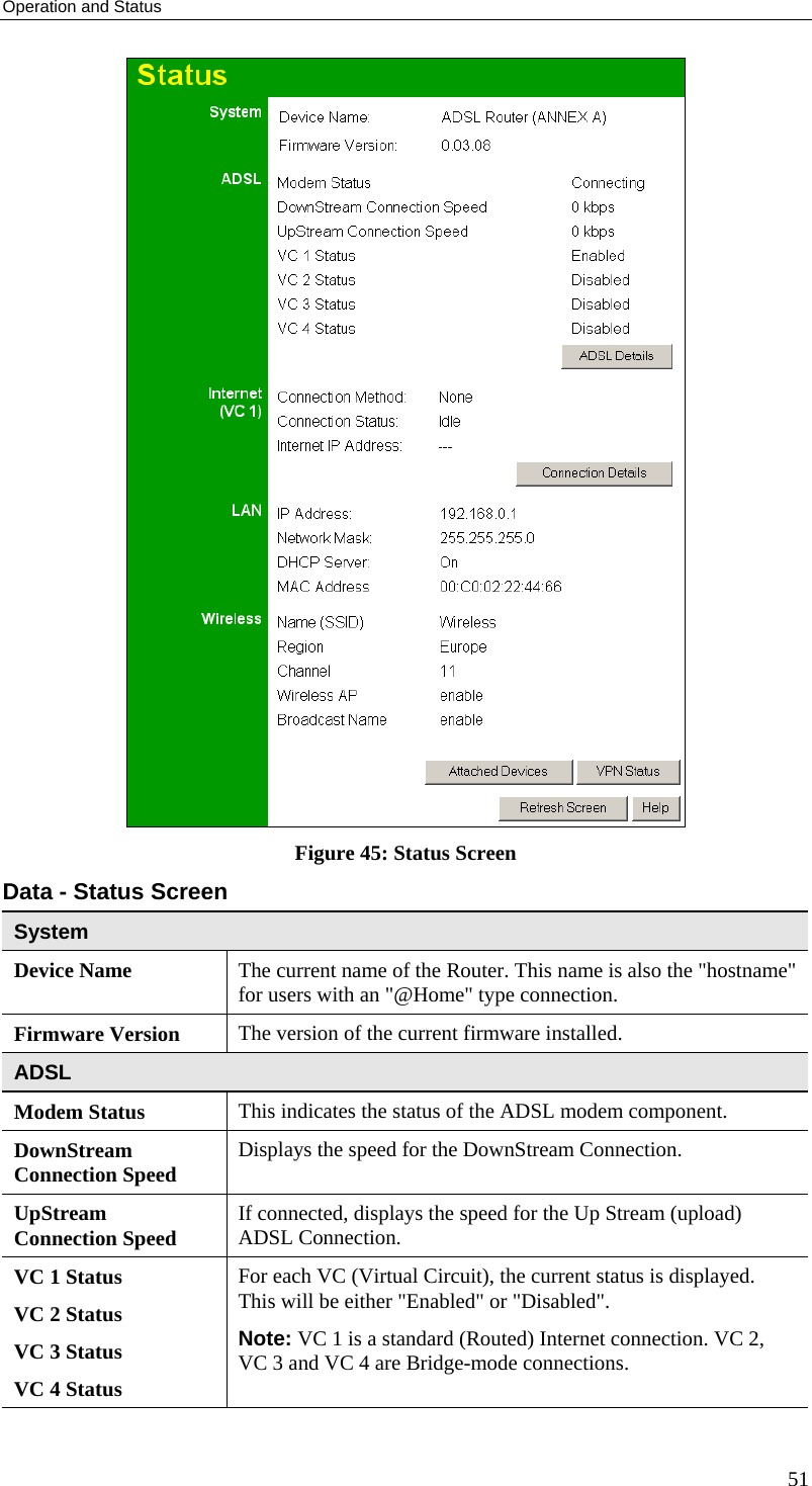
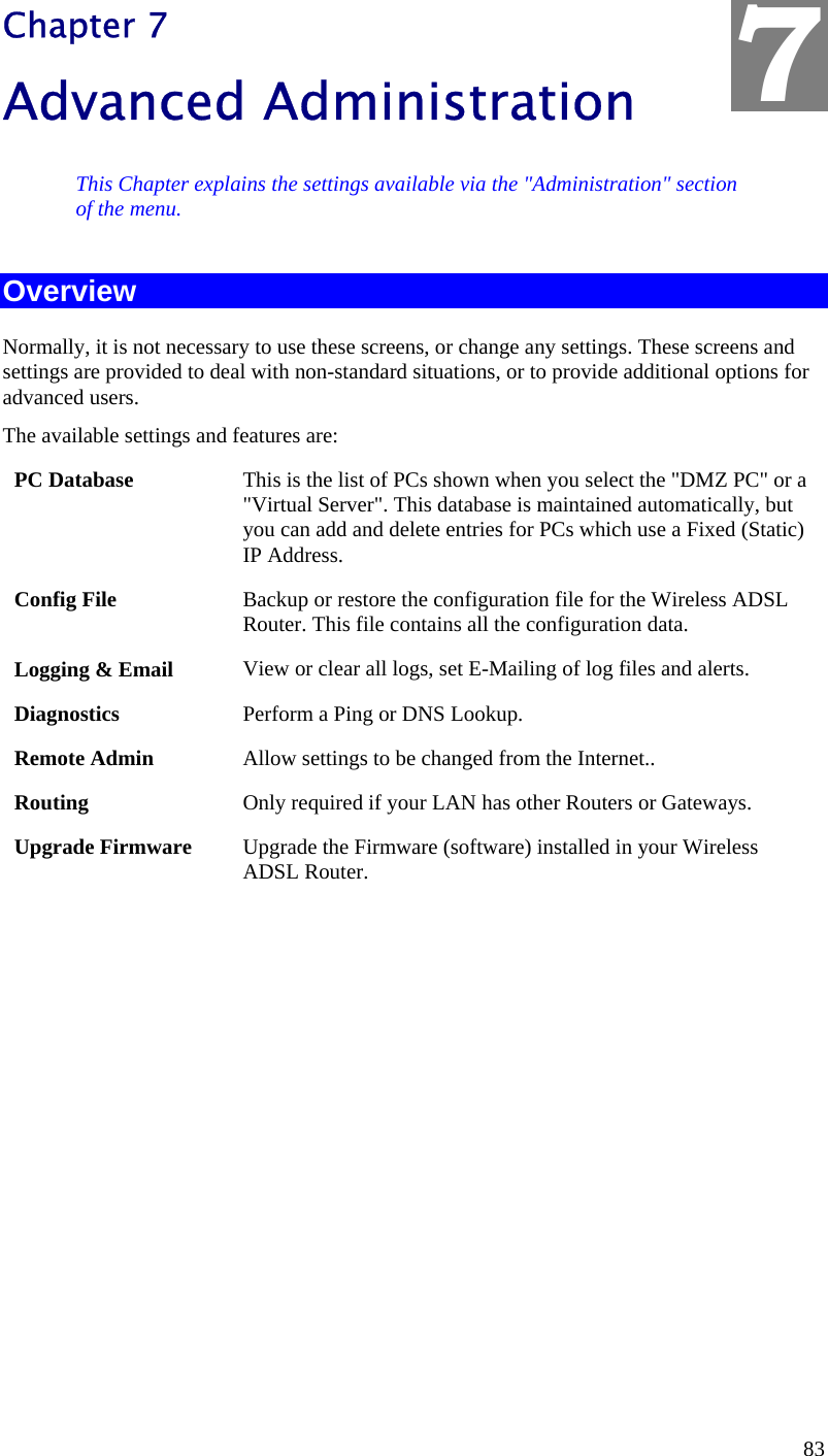

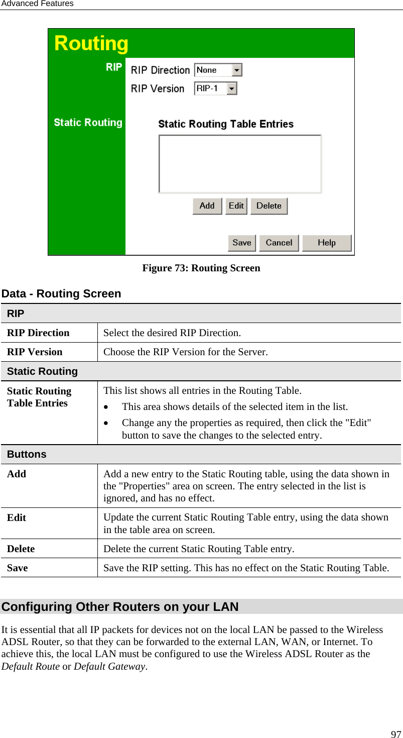
![Wireless ADSL Router User Guide Routing Overview • If you don't have other Routers or Gateways on your LAN, you can ignore the "Routing" page completely. • If the Wireless ADSL Router is only acting as a Gateway for the local LAN segment, ignore the "Routing" page even if your LAN has other Routers. • If your LAN has a standard Router (e.g. Cisco) on your LAN, and the Wireless ADSL Router is to act as a Gateway for all LAN segments, enable RIP (Routing Information Protocol) and ignore the Static Routing table. • If your LAN has other Gateways and Routers, and you wish to control which LAN segments use each Gateway, do NOT enable RIP (Routing Information Protocol). Configure the Static Routing table instead. (You also need to configure the other Routers.) • If using Windows 2000 Data center Server as a software Router, enable RIP on the Wireless ADSL Router, and ensure the following Windows 2000 settings are correct: • Open Routing and Remote Access • In the console tree, select Routing and Remote Access , [server name], IP Routing, RIP • In the "Details" pane, right-click the interface you want to configure for RIP version 2, and then click "Properties". • On the "General" tab, set Outgoing packet protocol to "RIP version 2 broadcast", and Incoming packet protocol to "RIP version 1 and 2". Routing Screen The routing table is accessed by the Routing link on the Administration menu. Using this Screen Generally, you will use either RIP (Routing Information Protocol) OR the Static Routing Table, as explained above, although is it possible to use both methods simultaneously. Static Routing Table • If RIP is not used, an entry in the routing table is required for each LAN segment on your Network, other than the segment to which this device is attached. • The other Routers must also be configured. See Configuring Other Routers on your LAN later in this chapter for further details and an example. 96](https://usermanual.wiki/Sercomm/IP806GAV3/User-Guide-695538-Page-99.png)