Sercomm MDC835 HD Wi-Fi Mini Dome Camera User Manual ADT MDC835 0729 QIG 2 ICupdate
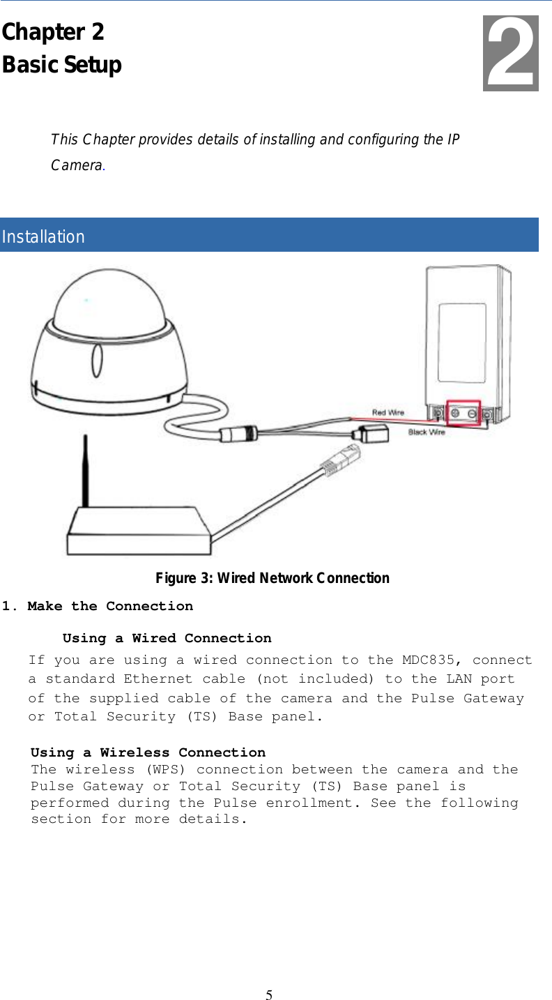
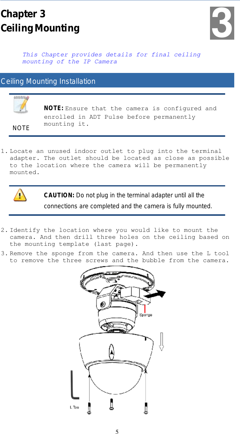
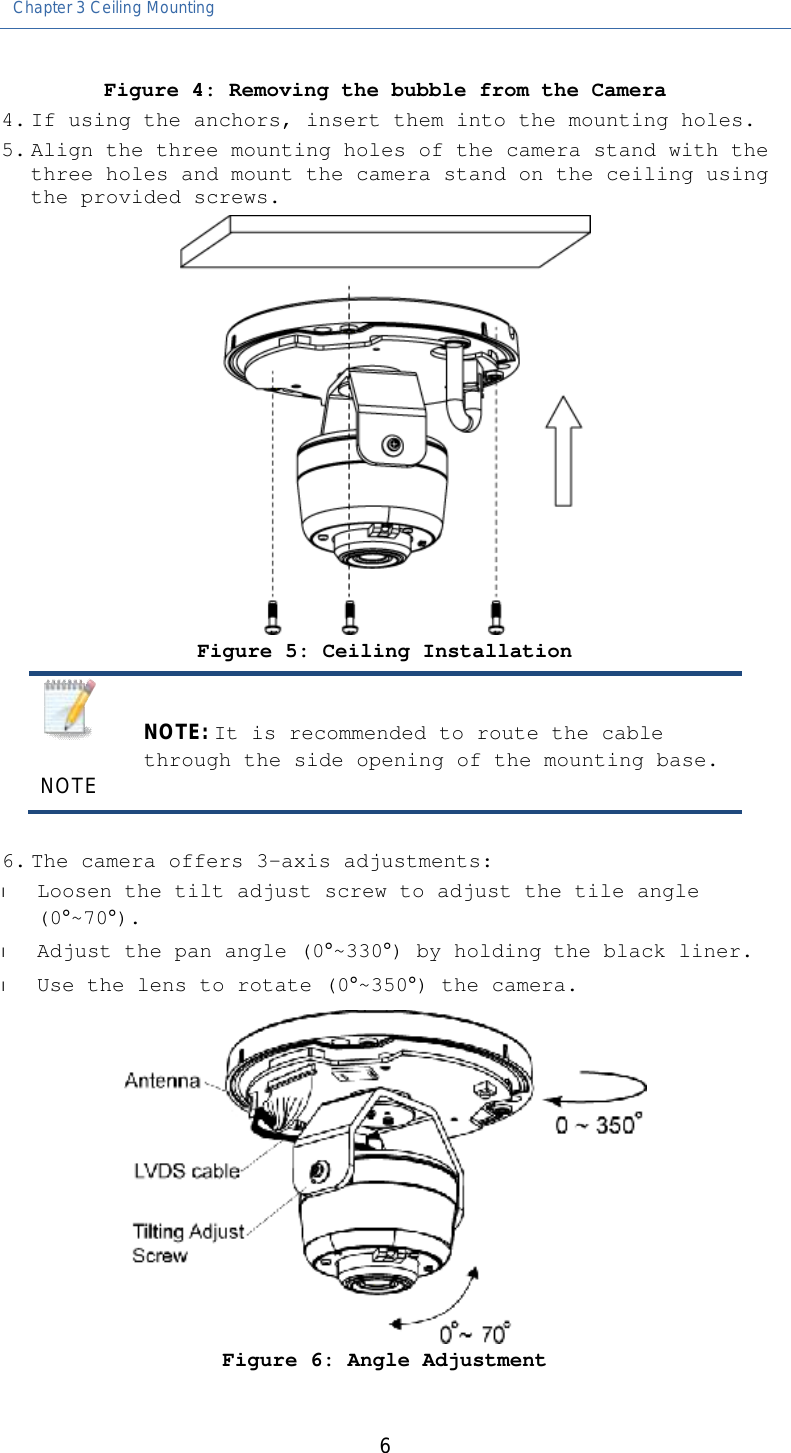
Sercomm Corporation HD Wi-Fi Mini Dome Camera ADT MDC835 0729 QIG 2 ICupdate
UserManual.wiki
>
Sercomm
>
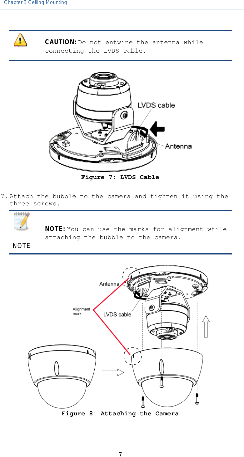
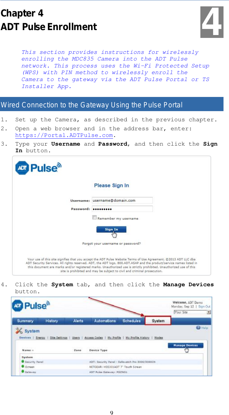
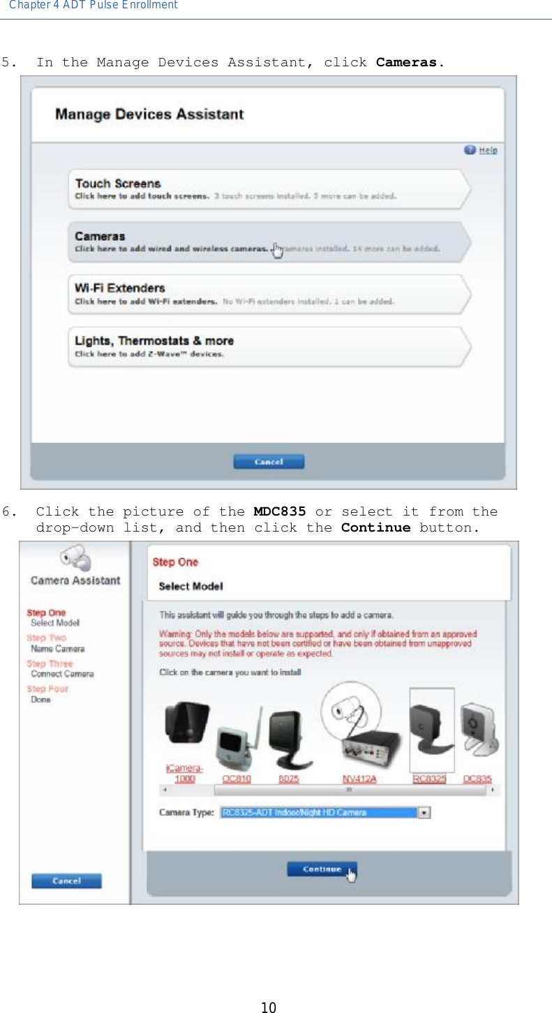
MDC835 User Manual
User Manual
Navigation menu
Upload a User Manual
Namespaces
Wiki Guide
HTML
PDF
Info
Views
User Manual
Discussion / Help
Navigation