Sercomm NA300 Z-WAVE BRIDGE User Manual
Sercomm Corporation Z-WAVE BRIDGE
UserManual.wiki
>
Sercomm
>
NA300 User Manual
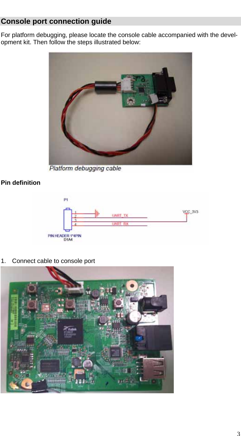
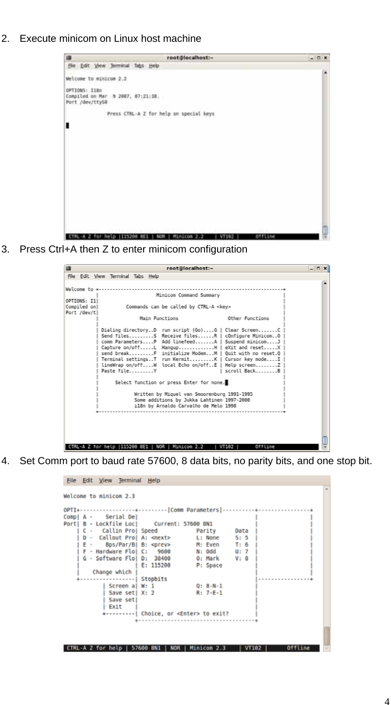
USERS MANUAL
Navigation menu
Upload a User Manual
Namespaces
Wiki Guide
HTML
PDF
Info
Views
User Manual
Discussion / Help
Navigation