USERS MANUAL
NA300
Z-Wave Bridge
User Guide

i
Table of Contents
CHAPTER 1 INTRODUCTION...................................................................................... 1
Package Contents ................................................................................................ 1
Specfication .......................................................................................................... 1
CHAPTER 2 BOARD DESCRIPTION .......................................................................... 2
Components and connectors.............................................................................. 2
CHAPTER 3 FCC STATEMENT................................................................................... 5
Copyright 2011. All Rights Reserved.
Document Version: 1.0
All trademarks and trade names are the properties of their respective owners.

1
Chapter 1
Introduction
This Chapter provides an overview of the Z-Wave Bridge's features
and capabilities.
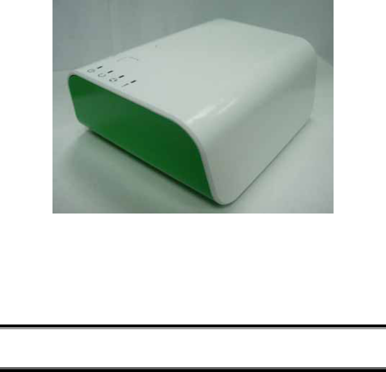
Congratulations on the purchase of your new Z-Wave Bridge. The Z-Wave Bridge is a
consumer electronic device, which is used for home monitoring and security.
Package Contents
The following items should be included:
• The Z-Wave Bridge Unit
• Power Adapter
• Batteries
If any of the above items are damaged or missing, please contact your dealer imme-
diately.
Specfication
• DDR2 SDRAM 64MB
• NAND 32MB Flash
• One Ethernet port with RJ45 connectors.
• Z-Wave Function
• One USB 2.0 ports
• Add button
• Remove button
• Reset button
• One Internal antennae
1
2
Chapter 2
Board Description
This Chapter provides board description for the Z-Wave Bridge.
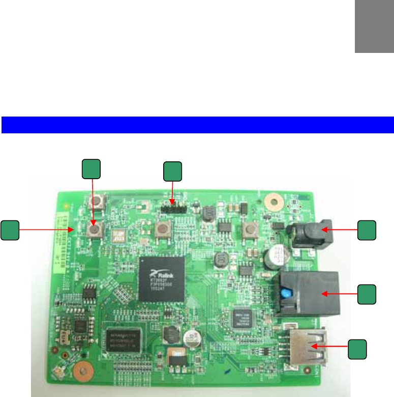
Components and connectors
y 1. USB type A connector
• 2. LAN port
• 3. Push buttons
• 4. Console port
• 5. LEDs
• 6. DC power jack
2
1
2
3 4
5 6
3
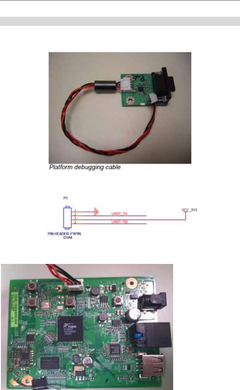
Console port connection guide
For platform debugging, please locate the console cable accompanied with the devel-
opment kit. Then follow the steps illustrated below:
Pin definition
1. Connect cable to console port
4
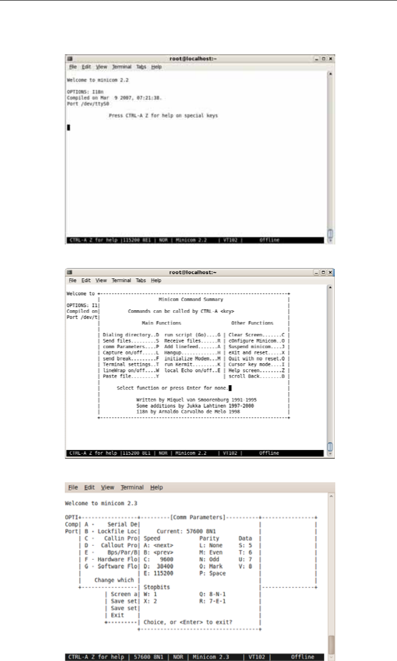
2. Execute minicom on Linux host machine
3. Press Ctrl+A then Z to enter minicom configuration
4. Set Comm port to baud rate 57600, 8 data bits, no parity bits, and one stop bit.

5
Chapter 3
FCC STATEMENT 3
FCC Statement
This equipment has been tested and found to comply with the limits for a Class B digital device, pursuant
to part 15 of the FCC rules. These limits are designed to provide reasonable protection against harmful
interference in a residential installation. This equipment generates, uses and can radiate radio frequency
energy and, if not installed and used in accordance with the instructions, may cause harmful interference
to radio communications. However, there is no guarantee that interference will not occur in a particular
installation. If this equipment does cause harmful interference to radio or television reception, which can
be determined by turning the equipment off and on, the user is encouraged to try to correct the interfer-
ence by one or more of the following measures:
-Reorient or relocate the receiving antenna.
-Increase the separation between the equipment and receiver.
-Connect the equipment into an outlet on a circuit different from that to which the receiver is connected.
-Consult the dealer or an experienced radio/TV technician for help.
You are cautioned that changes or modifications not expressly approved by the party responsible for
compliance could void your authority to operate the equipment.