Sercomm NV842 4 Channel wireless Video Server User Manual NV842 manual
Sercomm Corporation 4 Channel wireless Video Server NV842 manual
UserManual.wiki
>
Sercomm
>
NV842 User Manual
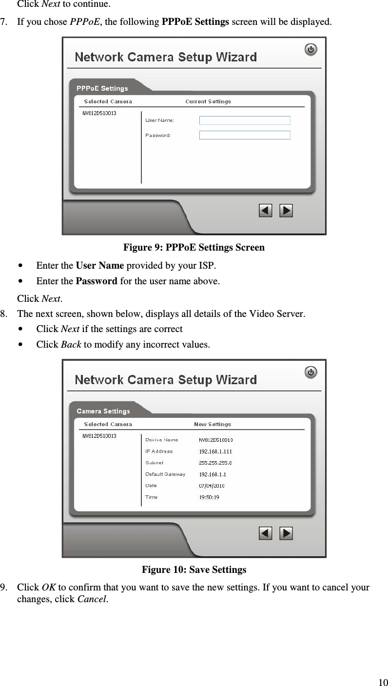
User manual
Navigation menu
Upload a User Manual
Namespaces
Wiki Guide
HTML
PDF
Info
Views
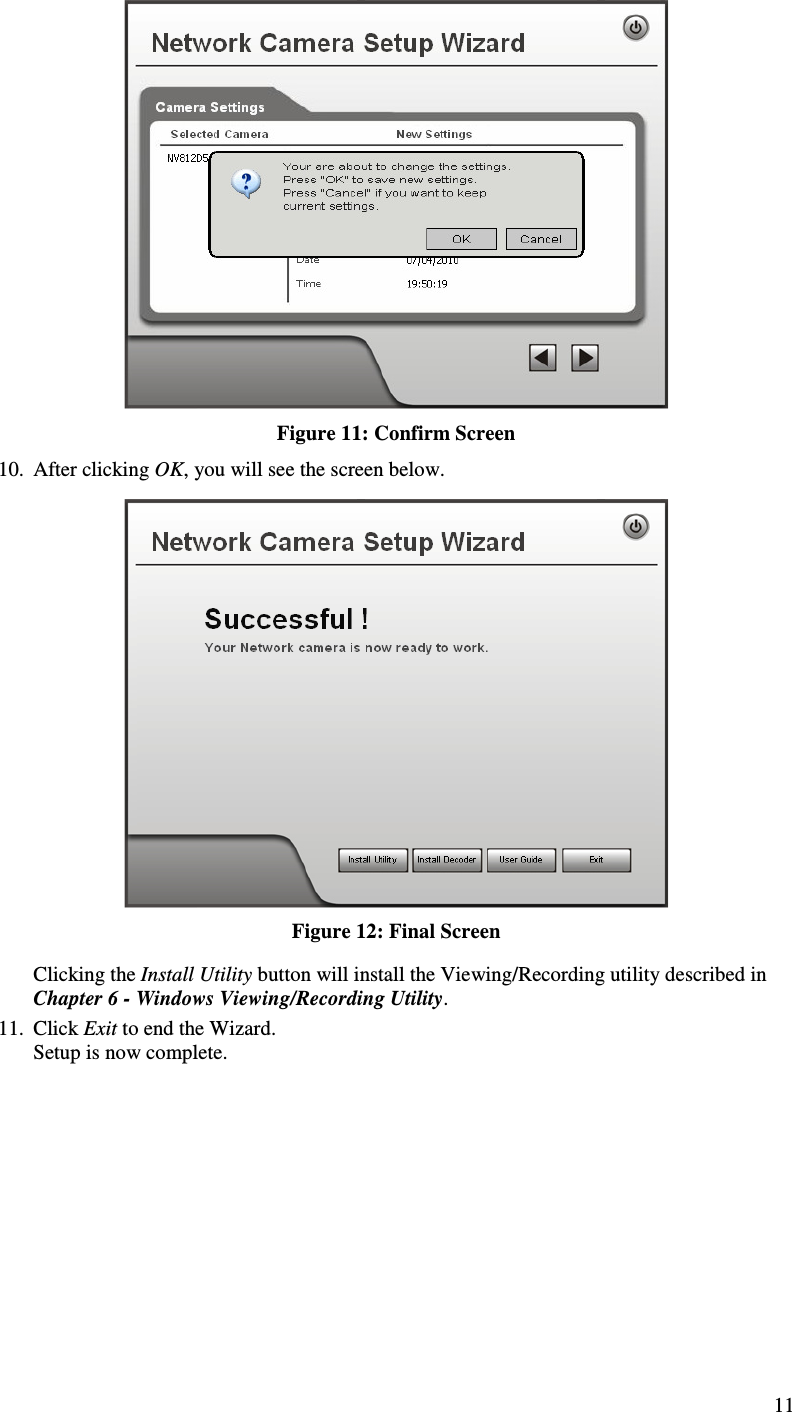
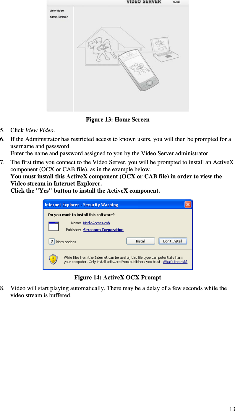
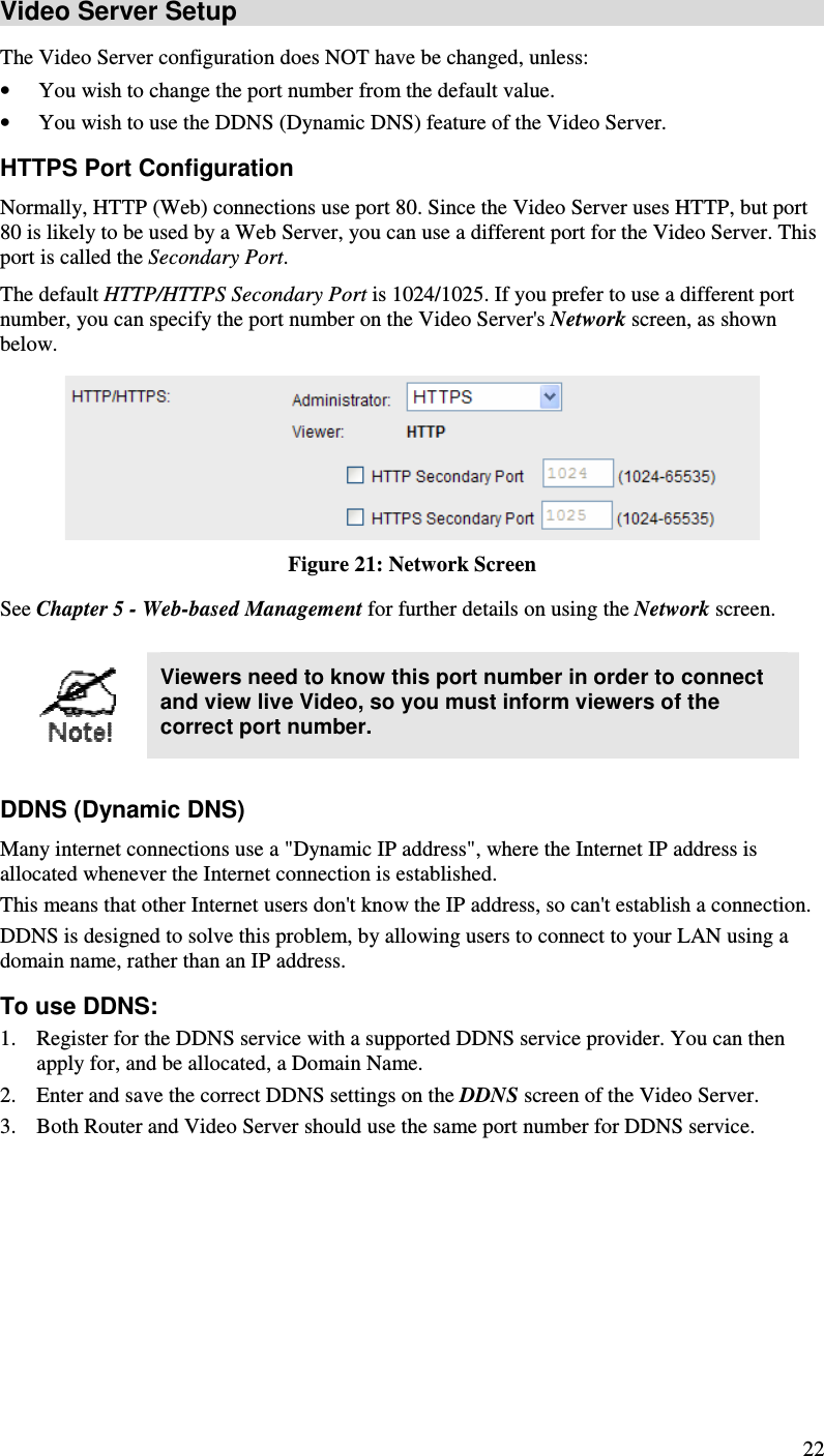
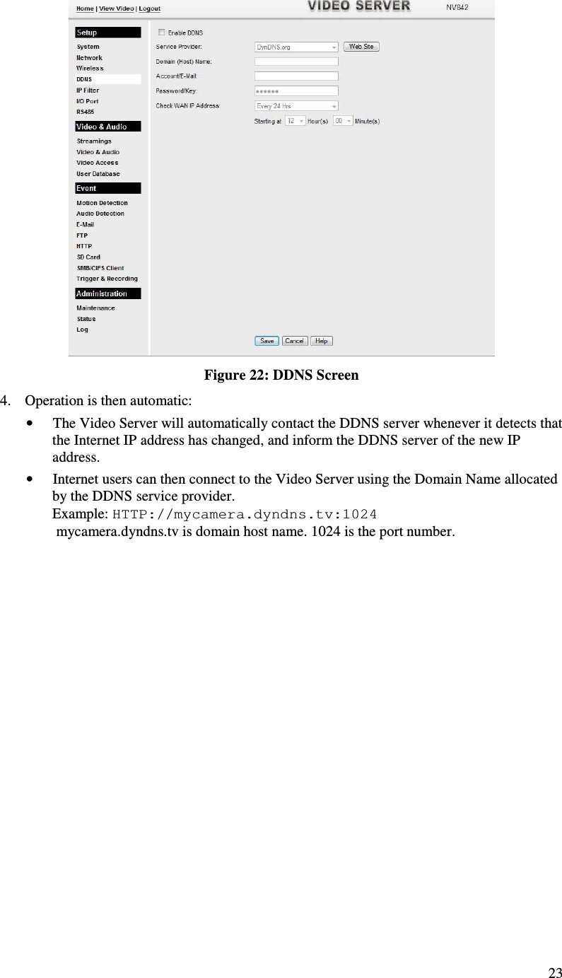
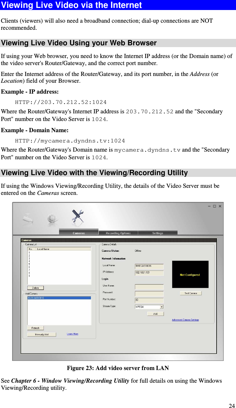
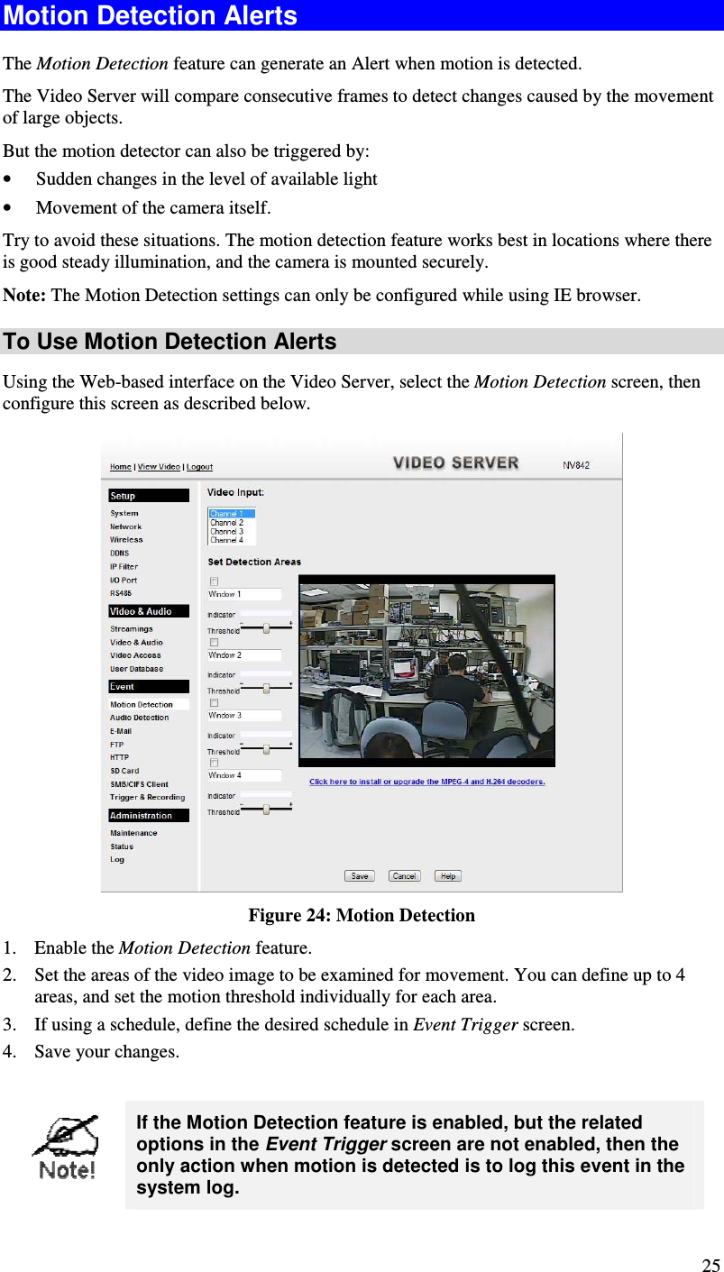
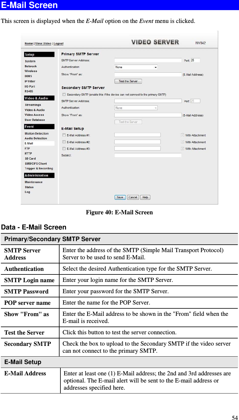
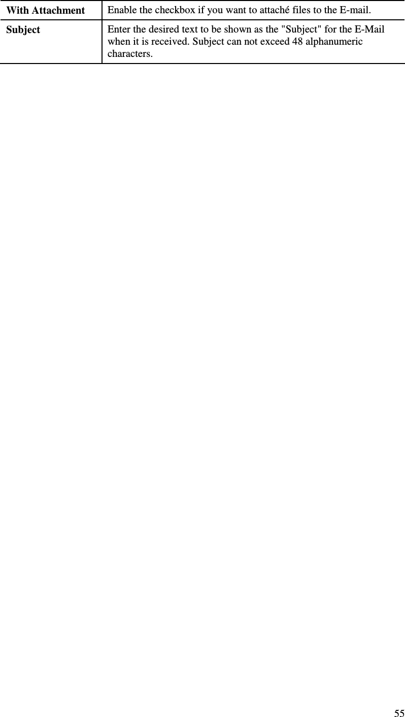
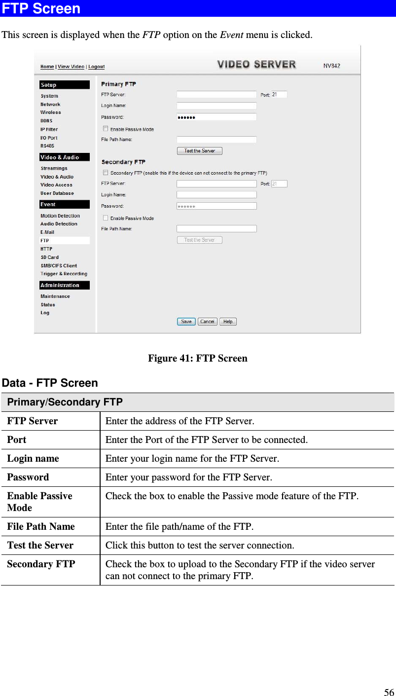
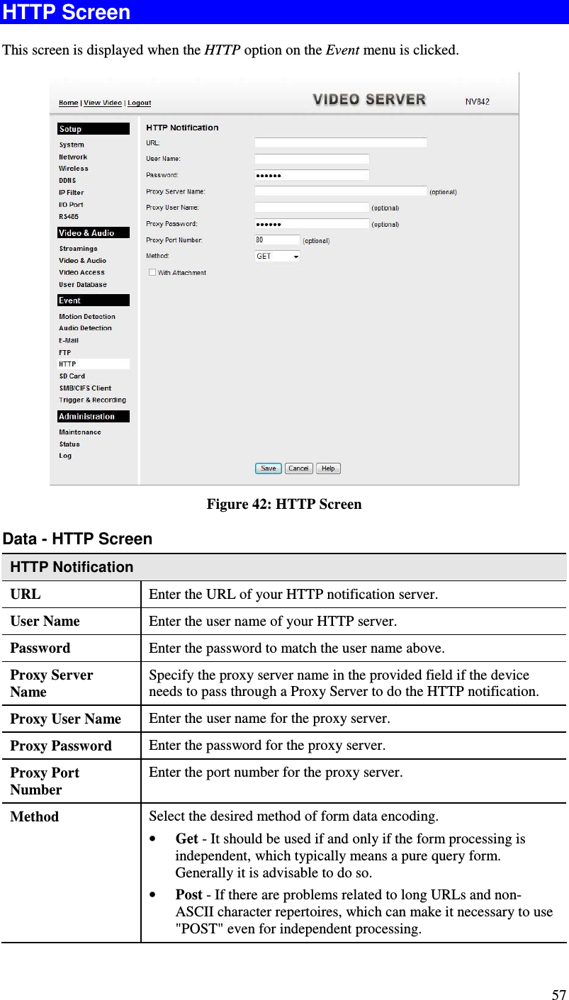
User Manual
Discussion / Help
Navigation