Sercomm OC400 Interactive Services - Outdoor Camera User Manual
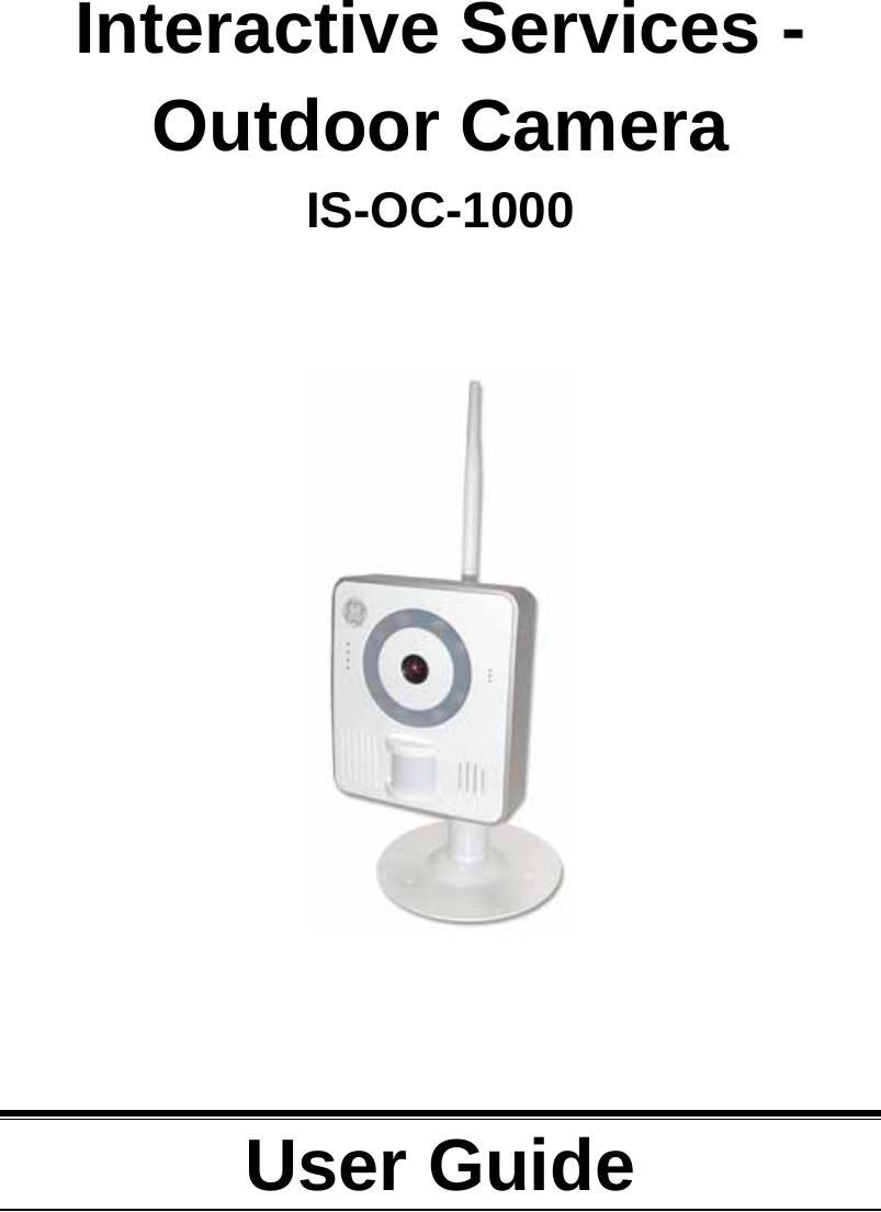
Sercomm Corporation Interactive Services - Outdoor Camera
UserManual.wiki
>
Sercomm
>
OC400 User Manual
User manual
Navigation menu
Upload a User Manual
Namespaces
Wiki Guide
HTML
PDF
Info
Views
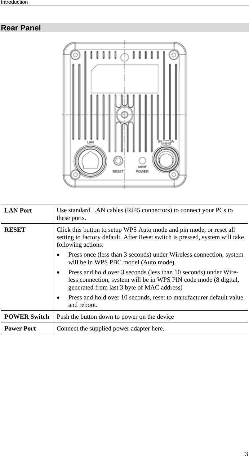
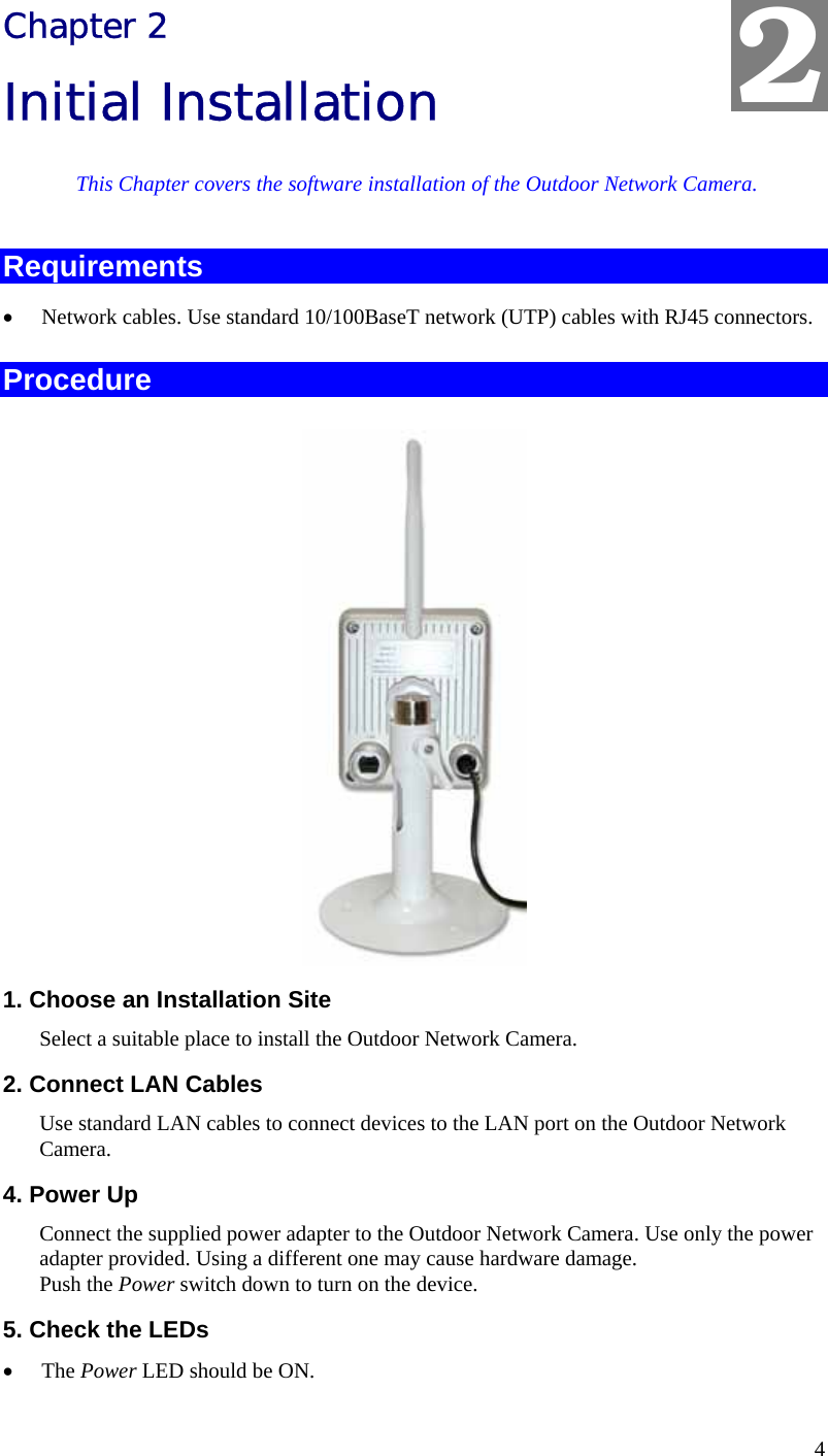
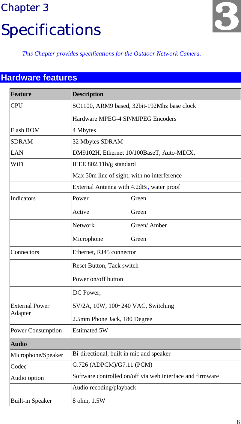
User Manual
Discussion / Help
Navigation
![Wireless Adapter User Guide 10 This device has been designed to operate with the antennas listed below, and having a maximum gain of [4.2] dB. Antennas not included in this list or having a gain greater than [4.2] dB are strictly prohibited for use with this device. The required antenna impedance is [50] ohms.](https://usermanual.wiki/Sercomm/OC400/User-Guide-1272810-Page-14.png)