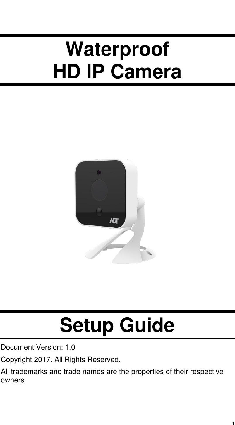
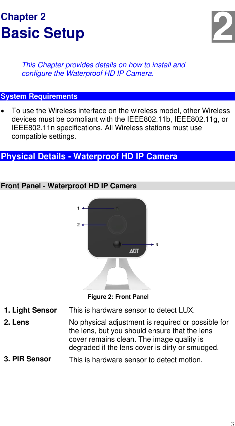
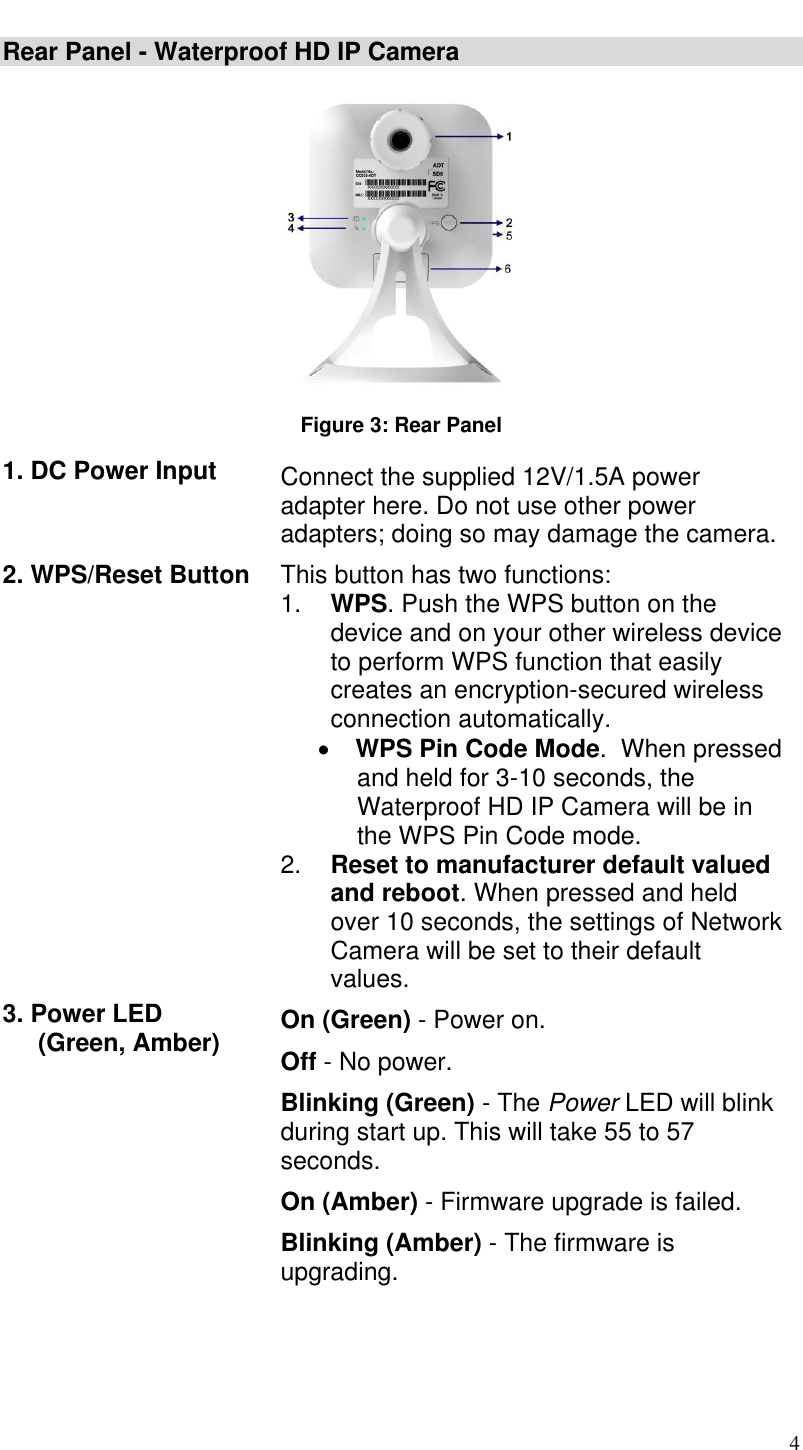
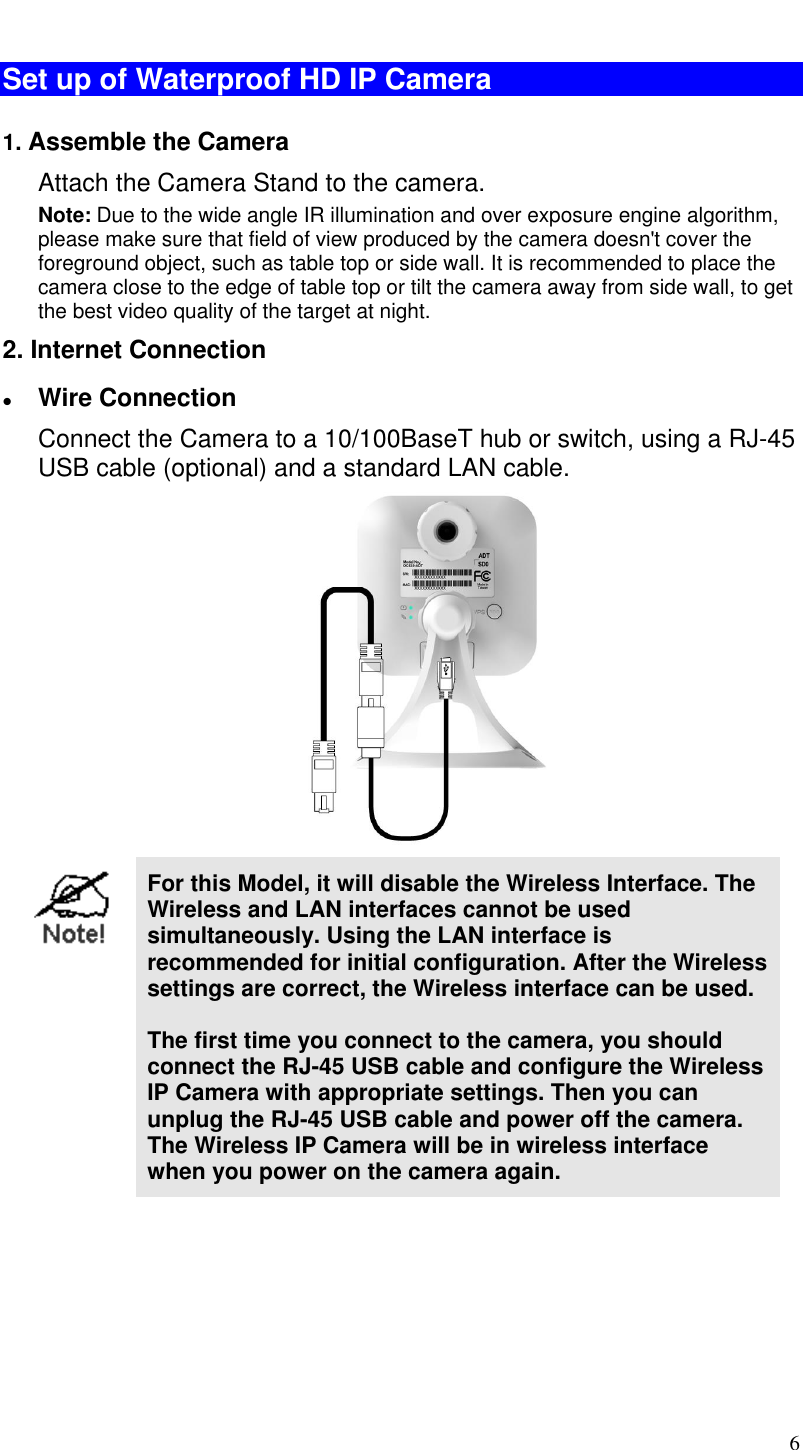
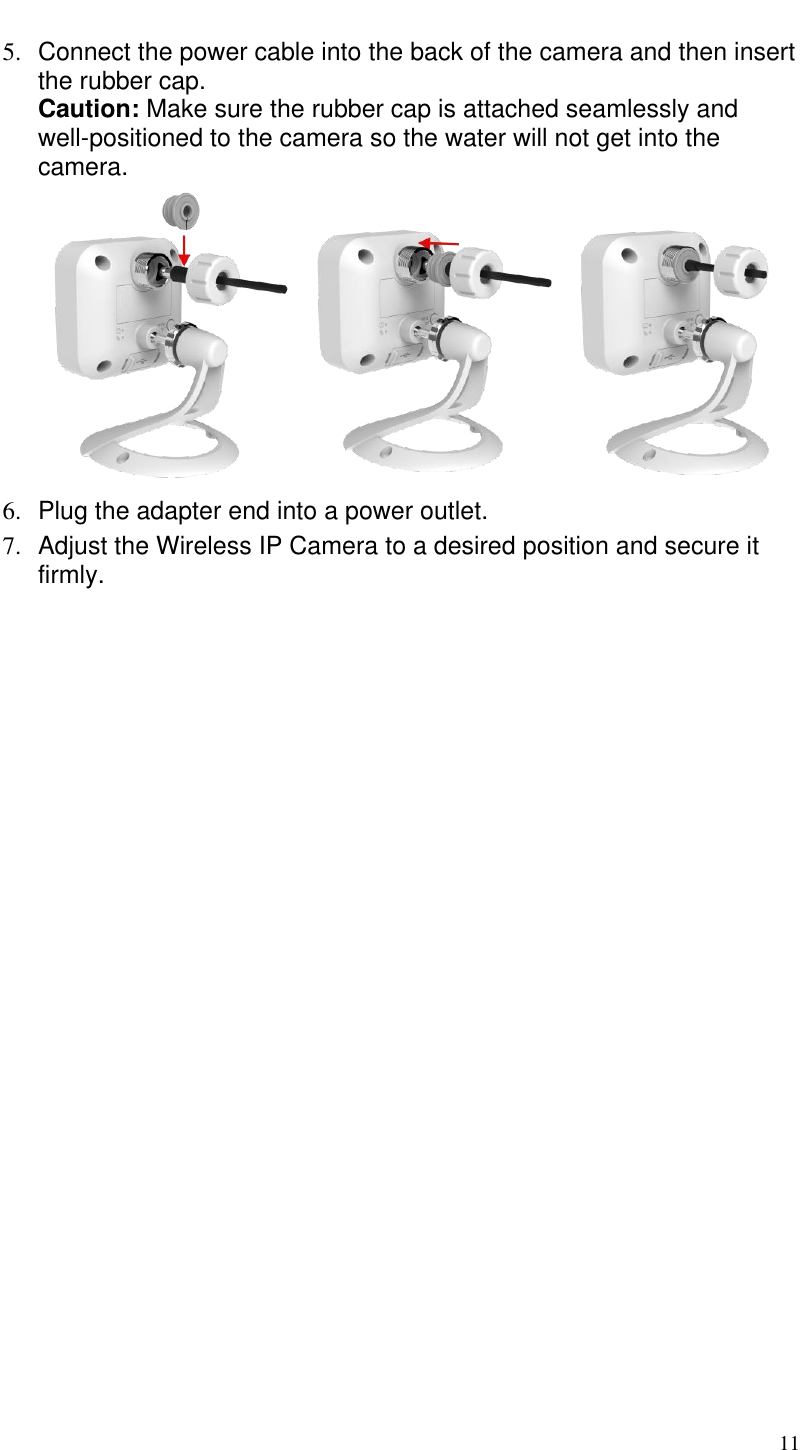
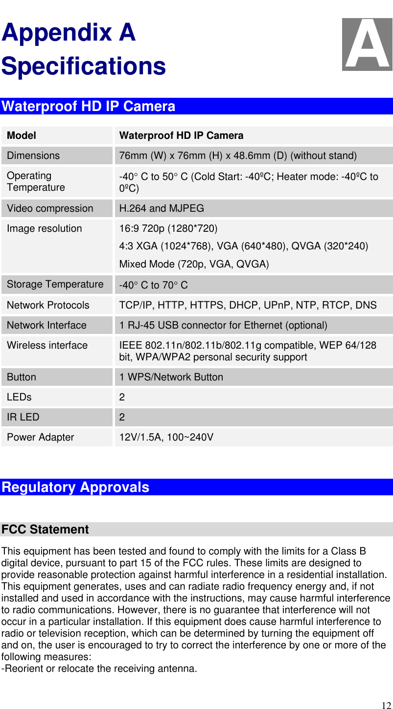
Sercomm OC835V3 HD IP Camera User Manual

Sercomm Corporation HD IP Camera Users Manual

Users Manual

 i   Waterproof  HD IP Camera          Setup Guide Document Version: 1.0 Copyright 2017. All Rights Reserved. All trademarks and trade names are the properties of their respective owners.
  Package Contents The following items should be included: If any of these items are damaged or missing, please contact your service provider immediately. 1.  Waterproof HD IP Camera x 1     2.  Stand x 1        3.  Screw Terminal Adapter x 1        4.  Screw/Anchor x 2  5.  DC In Rubber x 1  6.  Rubber Cap x 1  7. DC Barrel Connector with Two Wire Flying Lead x 1
 1 Chapter 1 Introduction This Chapter provides details of the Waterproof HD IP Camera's features, components and capabilities. Overview The Waterproof HD IP Camera has an Integrated Microcomputer and a high quality Mega Pixel Omni Vision CMOS Sensor, enabling it to display high quality live streaming video over your wired LAN, the Internet, and for the Waterproof HD IP Camera, an 802.11N Wireless LAN. Using enhanced H.264 technologies, the Waterproof HD IP Camera is able to stream high quality video and audio directly to your PC. The high compression capabilities of H.264 reduce network bandwidth requirements to amazingly low levels. This weather-resistant camera, which with the IP66 rated housing and internal heater, let you keep an eye on your belongings - even in harsh environments. It is also an all-in-one camera that has automatic and manual day/night switching, PIR sensor and built-in infrared LEDs, which can provide illumination around 5 meters long under low light conditions in a simple, economical manner.  Figure 1: Network Diagram - Waterproof HD IP Camera  1
 2 Features  Standalone Design.  The Waterproof HD IP Camera is a standalone system with built-in CPU and Video encoder. It requires only a power source and a connection to your LAN or Wireless LAN.  Dual Video Support. The Waterproof HD IP Camera can support H.264 and MJEPG video for different image compression.  Suitable for Home, Business or Public Facilities.  Whether for Home, Business or Public Facility surveillance, or just for entertainment and fun, the Waterproof HD IP Camera has the features you need.  Day/Night Switch:  With the day/night switching feature, you are able to view and record better images even in the dark of night.  IR LEDs Support. Each Waterproof HD IP Camera has two infrared LEDs. The LEDs can provide illumination around 5 meters long, that can help to output a better video quality while under low-light conditions such as on cloudy days, or in the morning or evening.   PIR (Passive Infrared Sensor) Support. The Waterproof HD IP Camera is embedded with a PIR Sensor, which senses infrared light radiating from human bodies in its field of view. This feature is very helpful in enhancing home security systems.  Built-in Heater.  The built-in Heater can support the camera to be used in the extreme cold outdoor climate applications. The heater should be turn on when temperature is below 6°C.  Micro-SD Card Slot. With the slot, you can insert the Micro-SD card to store recording files.   Wireless Features   Supports 11n Wireless Stations.  The 802.11n standard provides for backward compatibility with the 802.11b standard, so 802.11n, 802.11b and 802.11g Wireless stations can be used simultaneously.  Wired and Wireless Network Support. The Waterproof HD IP Camera supports either wired or wireless transmission.  WEP Support.  Full WEP support (64/128 Bit) on the Wireless interface is provided.  WPA/WPA2 Support.  The WPA Personal/WPA2 Personal standard is also supported, allowing advanced encryption of wireless data.  WPS Support. WPS (Wi-Fi Protected Setup) can simplify the process of connecting any device to the wireless network by using the push button configuration (PBC) on the Waterproof HD IP Camera, or entering a PIN code if there's no button.
 3 Chapter 2 Basic Setup This Chapter provides details on how to install and configure the Waterproof HD IP Camera. System Requirements   To use the Wireless interface on the wireless model, other Wireless devices must be compliant with the IEEE802.11b, IEEE802.11g, or IEEE802.11n specifications. All Wireless stations must use compatible settings. Physical Details - Waterproof HD IP Camera  Front Panel - Waterproof HD IP Camera   Figure 2: Front Panel  1. Light Sensor This is hardware sensor to detect LUX. 2. Lens No physical adjustment is required or possible for the lens, but you should ensure that the lens cover remains clean. The image quality is degraded if the lens cover is dirty or smudged. 3. PIR Sensor This is hardware sensor to detect motion. 2
 4 Rear Panel - Waterproof HD IP Camera    Figure 3: Rear Panel  1. DC Power Input Connect the supplied 12V/1.5A power adapter here. Do not use other power adapters; doing so may damage the camera. 2. WPS/Reset Button  This button has two functions: 1. WPS. Push the WPS button on the device and on your other wireless device to perform WPS function that easily creates an encryption-secured wireless connection automatically.  WPS Pin Code Mode.  When pressed             and held for 3-10 seconds, the                  Waterproof HD IP Camera will be in               the WPS Pin Code mode. 2. Reset to manufacturer default valued and reboot. When pressed and held over 10 seconds, the settings of Network Camera will be set to their default values. 3. Power LED  (Green, Amber) On (Green) - Power on. Off - No power. Blinking (Green) - The Power LED will blink during start up. This will take 55 to 57 seconds. On (Amber) - Firmware upgrade is failed. Blinking (Amber) - The firmware is upgrading.
 5 4. Network/Wireless LED  (Green, Amber) On (Green) - Network (Wireless or LAN) connection is available. Off - Wireless or LAN is not connected or camera is not sending/receiving data. Blinking (Green) - Data is being transmitted or received via the LAN or Wireless connection. On (Amber) - If the LED is on for 5 seconds and then off, the WPS function is failed. Blinking (Amber) - WPS function is being processed. 5. Micro SD Card Slot Insert the SD card into the slot for additional storage if needed. 6. LAN port Use a RJ-45 USB cable (optional) to connect your camera to a 10/100BaseT hub or switch. Note:    Plugging in the RJ-45 USB cable will disable the Wireless interface. Only 1 interface can be active at any time.  The RJ-45 USB cable should only be connected or disconnected when the camera is powered OFF. Attaching or detaching the RJ-45 USB cable while the camera is powered on does NOT switch the interface between wired and wireless.
 6 Set up of Waterproof HD IP Camera 1. Assemble the Camera Attach the Camera Stand to the camera. Note: Due to the wide angle IR illumination and over exposure engine algorithm, please make sure that field of view produced by the camera doesn't cover the foreground object, such as table top or side wall. It is recommended to place the camera close to the edge of table top or tilt the camera away from side wall, to get the best video quality of the target at night. 2. Internet Connection  Wire Connection Connect the Camera to a 10/100BaseT hub or switch, using a RJ-45 USB cable (optional) and a standard LAN cable.   For this Model, it will disable the Wireless Interface. The Wireless and LAN interfaces cannot be used simultaneously. Using the LAN interface is recommended for initial configuration. After the Wireless settings are correct, the Wireless interface can be used.  The first time you connect to the camera, you should connect the RJ-45 USB cable and configure the Wireless IP Camera with appropriate settings. Then you can unplug the RJ-45 USB cable and power off the camera. The Wireless IP Camera will be in wireless interface when you power on the camera again.
 7  Wireless Connection Press the WPS button on the camera for 3-5 seconds and on your other wireless device as well to establish a wireless connection automatically. The wireless connection is successful when the Network/WPS LED (green) remains on.   3. Power Up Use only the power adapter provided. Using a different one may cause hardware damage.  a.  Run the AC Wire to the spice connector. b.  Screw the red wire onto the positive (+) terminal of the terminal adapter. c.    Screw the black wire onto the negative (-) terminal of the terminal adapter. d.    Plug the terminal adapter into a power outlet.
 8  *Note: The operating temperature of power adapter is 0C to 40C. Please ensure the power adapter is indoor usage. 4. Check the LEDs  The Power LED will turn on briefly, then start blinking. It will blink during startup, which will take 55 to 57 seconds. After startup is completed, the Power LED should remain ON.  The Network/WPS LED should be ON.  Micro SD Card Installation 1. Remove the screw with a proper screwdriver, and then take the SD card cover out the camera.  2. Insert the micro SD card into the slot.
 9 * Optional: Mounting the Waterproof HD IP Camera *Note: Please ensure camera is configured and added to the network before permanent mounting.   Mount the Camera Mounting Suggestion Place the camera in a location near a power source. For mounting on a wall, please use the provided mounting plate. To get the best video quality for targets at night, make sure that the camera’s field of view does not include a large foreground object, such as tabletop or side wall. If installing on a tabletop, place the camera as close to the edge as possible, as demonstrated in the photos in row 1 below. If installing on a wall, angle the camera so that a minimal portion of the wall is visible, as demonstrated in the photos in row 2 below.
 10 1.  Identify the location for mounting the camera. 2. Align the two mounting holes at the bottom of the camera stand with the two screws, and mount the mounting plate onto the screws.  3.  Screw/attach the camera onto the camera stand.  4.  There are two methods for Internet connection:  Connect a USB to RJ-45 cable (Optional) to the USB port of            the Wireless IP Camera. Then use a standard LAN cable to            connect an available port on your router.  Press the WPS button on the Wireless IP Camera for 3-5            seconds and on your other wireless device as well to establish a            wireless connection automatically. The wireless connection is            successful when the Network/WPS LED (green) is on.
 11 5.  Connect the power cable into the back of the camera and then insert the rubber cap. Caution: Make sure the rubber cap is attached seamlessly and  well-positioned to the camera so the water will not get into the camera.  6.  Plug the adapter end into a power outlet. 7.  Adjust the Wireless IP Camera to a desired position and secure it firmly.
 12 Appendix A Specifications Waterproof HD IP Camera Model Waterproof HD IP Camera Dimensions 76mm (W) x 76mm (H) x 48.6mm (D) (without stand) Operating Temperature -40 C to 50 C (Cold Start: -40ºC; Heater mode: -40ºC to 0ºC) Video compression H.264 and MJPEG Image resolution 16:9 720p (1280*720) 4:3 XGA (1024*768), VGA (640*480), QVGA (320*240) Mixed Mode (720p, VGA, QVGA) Storage Temperature -40 C to 70 C Network Protocols TCP/IP, HTTP, HTTPS, DHCP, UPnP, NTP, RTCP, DNS Network Interface 1 RJ-45 USB connector for Ethernet (optional) Wireless interface  IEEE 802.11n/802.11b/802.11g compatible, WEP 64/128 bit, WPA/WPA2 personal security support Button 1 WPS/Network Button LEDs 2 IR LED 2 Power Adapter 12V/1.5A, 100~240V  Regulatory Approvals  FCC Statement This equipment has been tested and found to comply with the limits for a Class B digital device, pursuant to part 15 of the FCC rules. These limits are designed to provide reasonable protection against harmful interference in a residential installation. This equipment generates, uses and can radiate radio frequency energy and, if not installed and used in accordance with the instructions, may cause harmful interference to radio communications. However, there is no guarantee that interference will not occur in a particular installation. If this equipment does cause harmful interference to radio or television reception, which can be determined by turning the equipment off and on, the user is encouraged to try to correct the interference by one or more of the following measures: -Reorient or relocate the receiving antenna. A
 13 -Increase the separation between the equipment and receiver. -Connect the equipment into an outlet on a circuit different from that to which the receiver is connected. -Consult the dealer or an experienced radio/TV technician for help. To assure continued compliance, any changes or modifications not expressly approved by the party responsible for compliance could void the user’s authority to operate this equipment. (Example- use only shielded interface cables when connecting to computer or peripheral devices).  RF Exposure Part This equipment complies with FCC RF radiation exposure limits set forth for an uncontrolled environment. This transmitter must not be co-located or operating in conjunction with any other antenna or transmitter.  This equipment should be installed and operated with a minimum distance of 20 centimeters between the radiator and your body.   IC Statement This device complies with Industry Canada’s licence-exempt RSSs. Operation is subject to the following two conditions: (1) This device may not cause interference; and (2) This device must accept any interference, including interference that may cause undesired operation of the device.  Le présent appareil est conforme aux CNR d’Industrie Canada applicables aux appareils radio exempts de licence. L’exploitation est autorisée aux deux conditions suivantes : (1) l’appareil ne doit pas produire de brouillage; (2) l’utilisateur de l’appareil doit accepter tout brouillage radioélectrique subi, même si le brouillage est susceptible d’en compromettre le fonctionnement. This transmitter must not be co-located or operating in conjunction with any other antenna or transmitter. This equipment should be installed and operated with a minimum distance of 20 centimeters between the radiator and your body.   Cet émetteur ne doit pas être Co-placé ou ne fonctionnant en même temps qu'aucune autre antenne ou émetteur. Cet équipement devrait être installé et actionné avec une distance minimum de 20 centimètres entre le radiateur et votre corps.  Exposure: This device meets the exemption from the routine evaluation limits in section 2.5 of RSS102 and users can obtain Canadian information on RF exposure and compliance.  Le dispositif rencontre l'exemption des limites courantes d'évaluation dans la section 2.5 de RSS 102 et la conformité à l'exposition de RSS-102 rf, utilisateurs peut obtenir l'information canadienne sur l'exposition et la conformité de rf.

Navigation menu