Sercomm RC8221V2 Wireless Network Camera User Manual RC8221v2 Manual v1 1028
Sercomm Corporation Wireless Network Camera RC8221v2 Manual v1 1028
UserManual.wiki
>
Sercomm
>
RC8221V2 User Manual
User manual
Navigation menu
Upload a User Manual
Namespaces
Wiki Guide
HTML
PDF
Info
Views
User Manual
Discussion / Help
Navigation
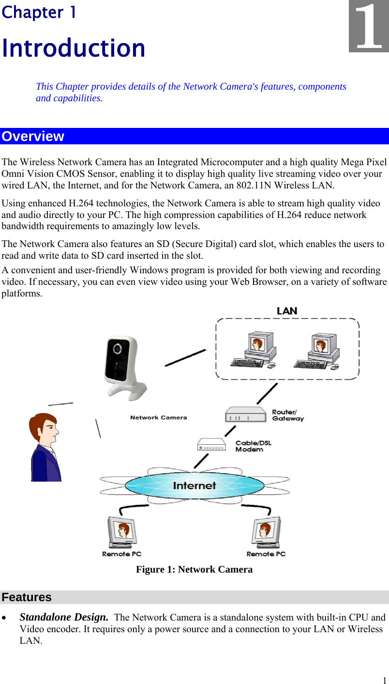
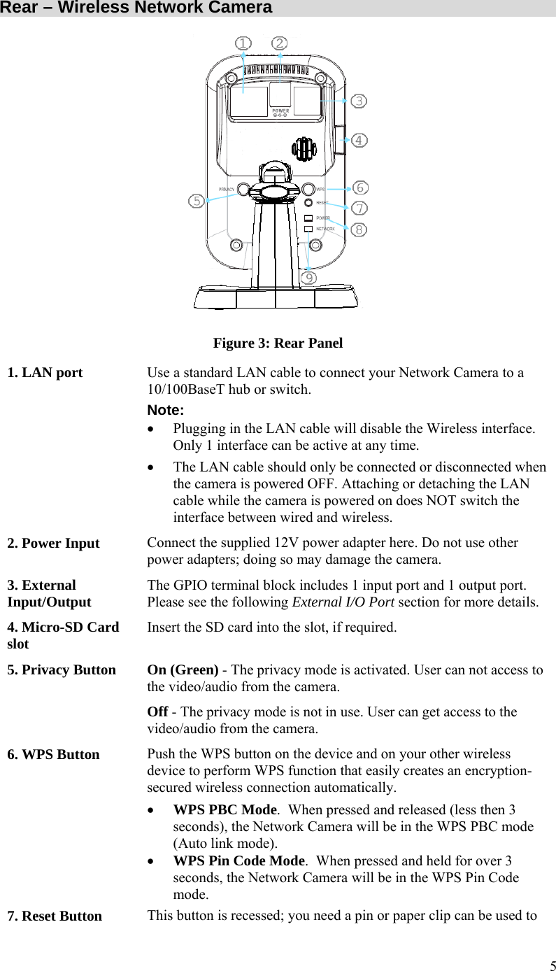
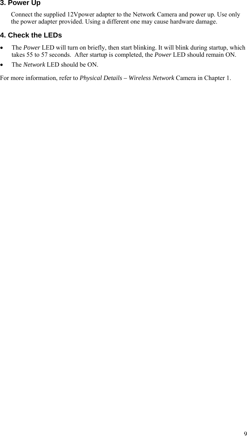
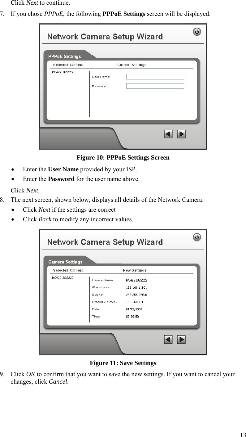
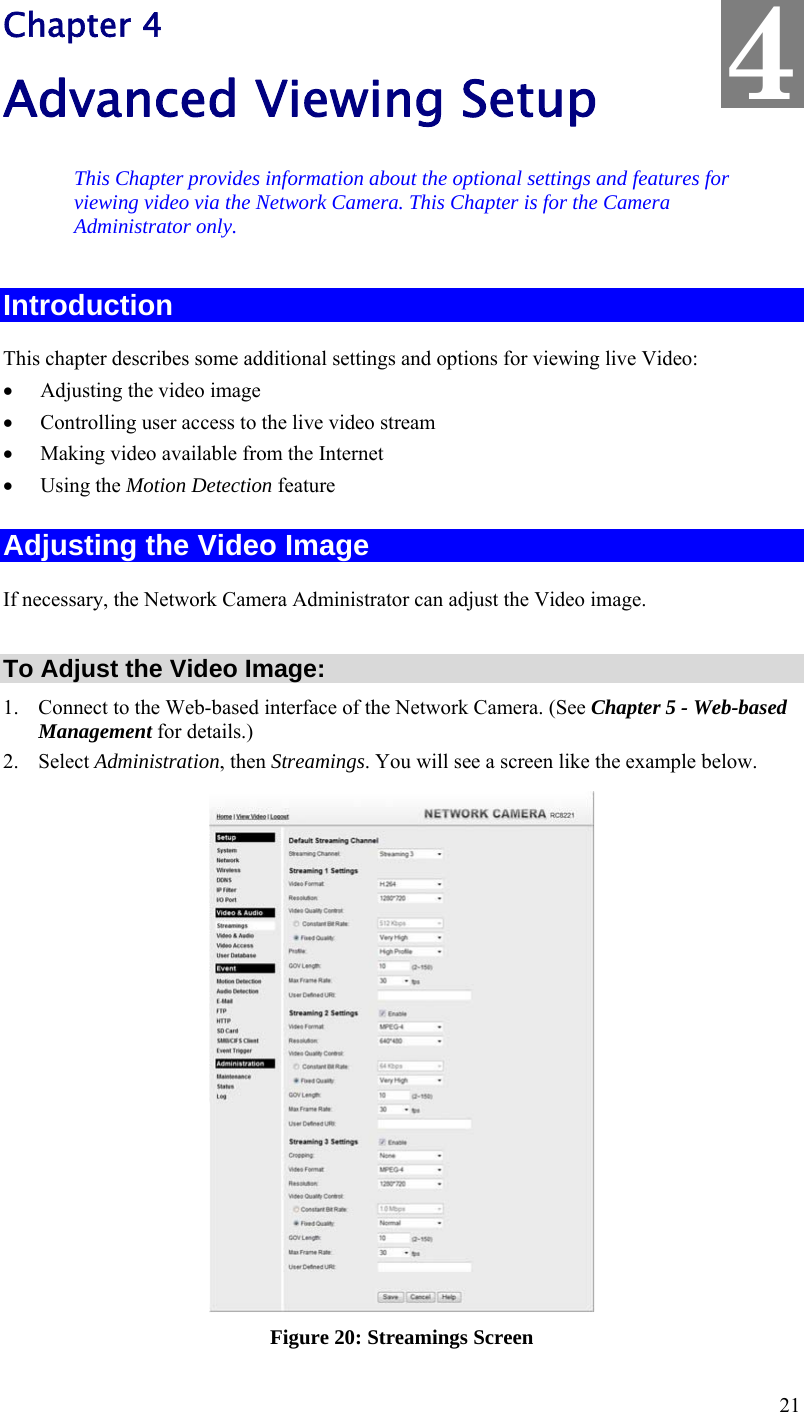
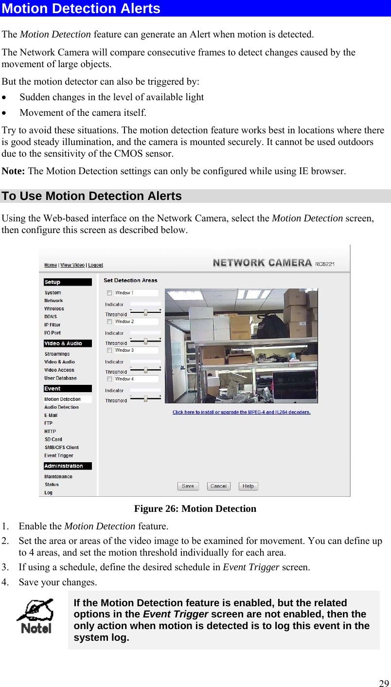
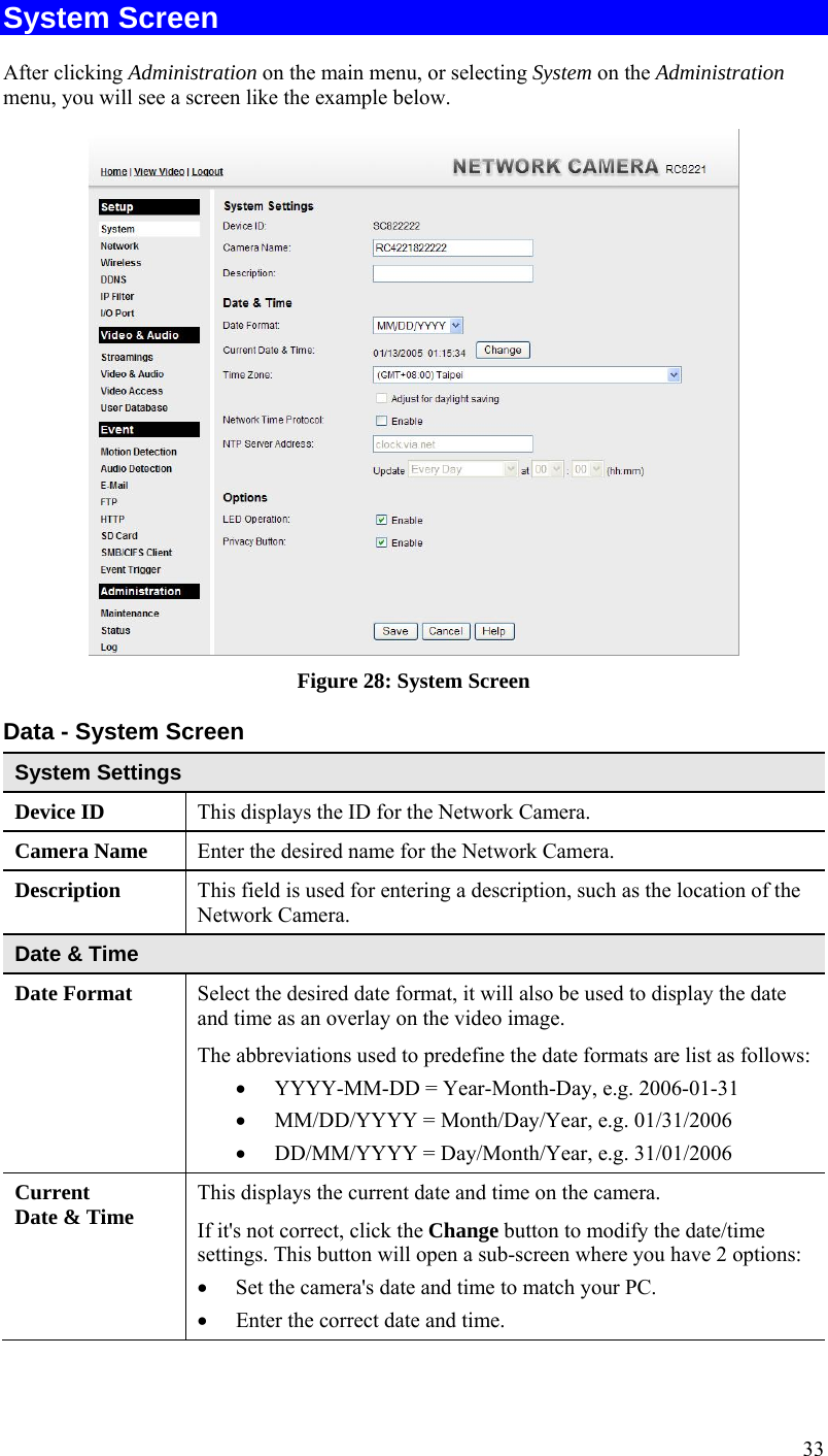
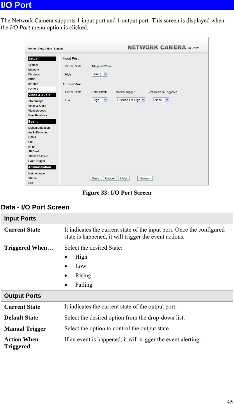

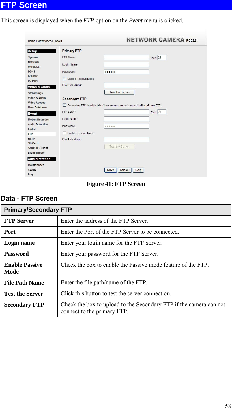
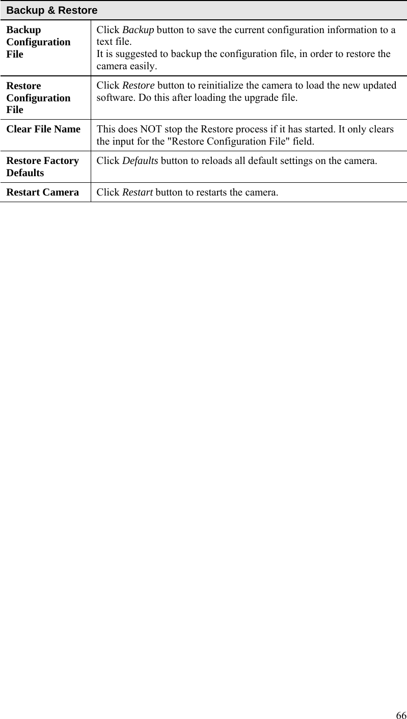
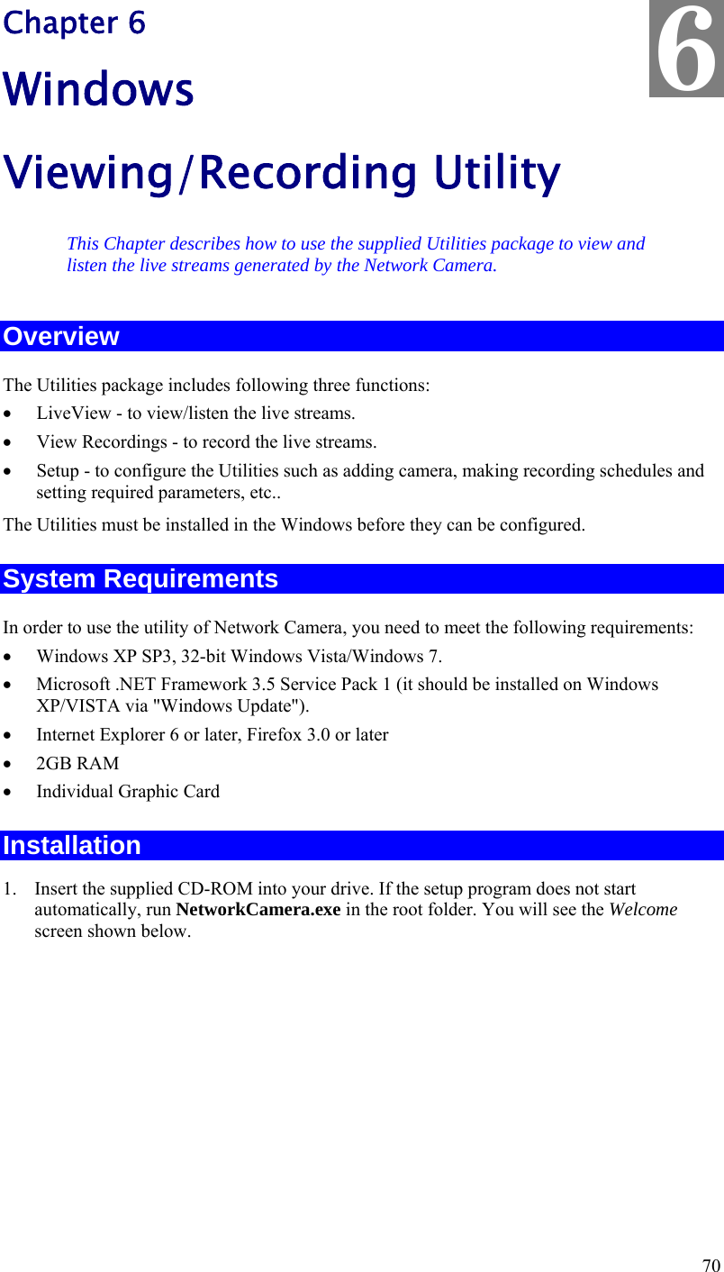
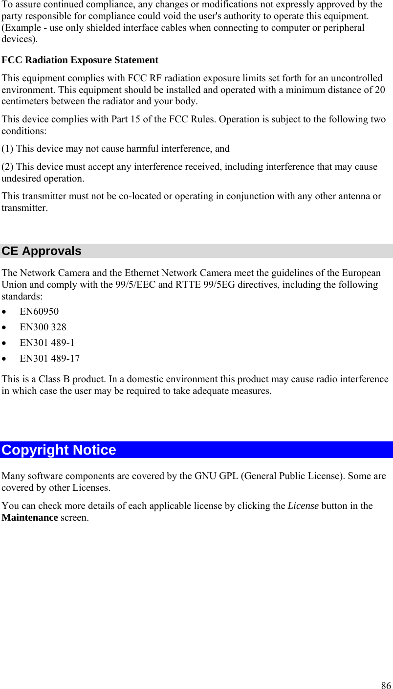
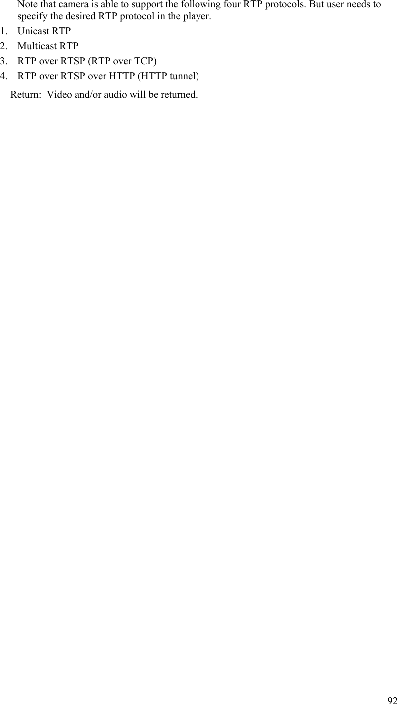
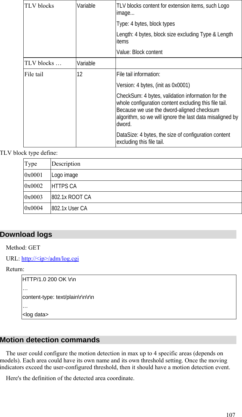
![90 … content-type: text/plain\r\n \r\n current_ resolution=A\r\n current_framerate=B\r\n The A and B are in the following format. Parameter Value and description A Image resolution 1: 160x120 (or 160x128, 176x120 (NTSC)/ 176x144(PAL), depends on models) 2: 320x240 (or 352x240(NTSC)/ 352x288(PAL), depends on models) 3: 640x480 (or 704x480(NTSC)/ 704x576(PAL), depends on models) 4: 1280x960 (depends on models) B Frame rate 1 ~ 30fps Snapshot Method: GET URL: http://<ip>/img/snapshot.cgi?[size=<value>][&quality=<value>] Parameter Value and description size Image resolution 1: 160x120 (or 160x128, 176x120 (NTSC)/ 176x144(PAL), depends on models) 2: 320x240 (or 352x240(NTSC)/ 352x288(PAL), depends on models) 3: 640x480 (or 704x480(NTSC)/ 704x576(PAL), depends on models) 4: 1280x720 (depends on models) quality Quality level 1: Very high 2: High 3: Normal 4: Low 5: Very low Example 1: To snapshot a 640x480 (or 704x480(NTSC)/ 704x576(PAL), depends on models) very high quality JPEG image from network camera 192.168.0.99. http://192.168.0.99/img/snapshot.cgi?size=3&quality=1 Example 2: To snapshot a JPEG image from network camera 192.168.0.99 (with current resolution and quality) http://192.168.0.99/img/snapshot.cgi Example 3: To snapshot a low quality JPEG image with current resolution from the network camera 192.168.0.99. http://192.168.0.99/img/snapshot.cgi?quality=4 Return: A JPEG image will be returned to client with user specified resolution and quality. HTTP/1.0 200 OK\r\n](https://usermanual.wiki/Sercomm/RC8221V2/User-Guide-2438184-Page-93.png)
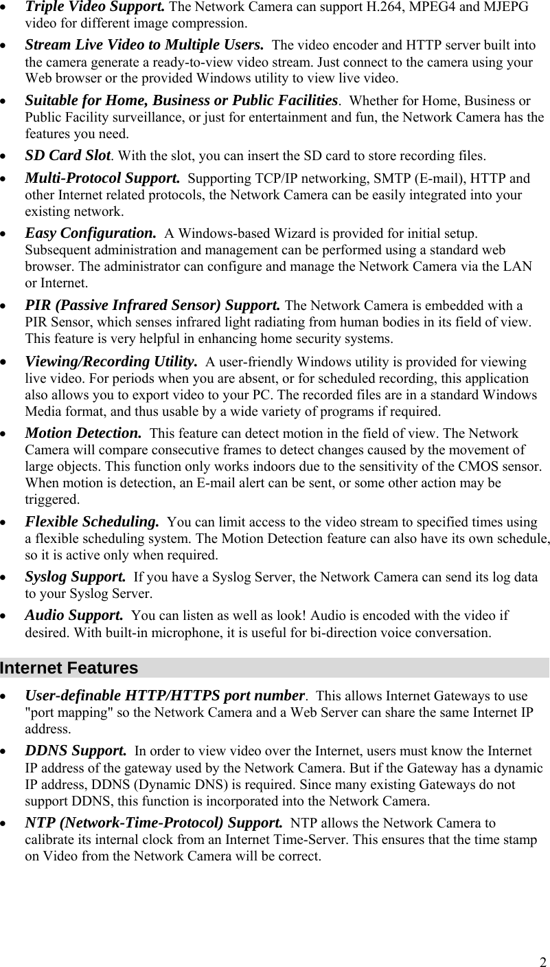
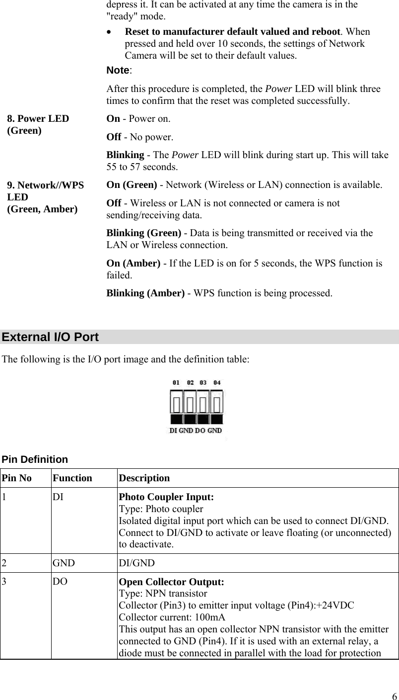
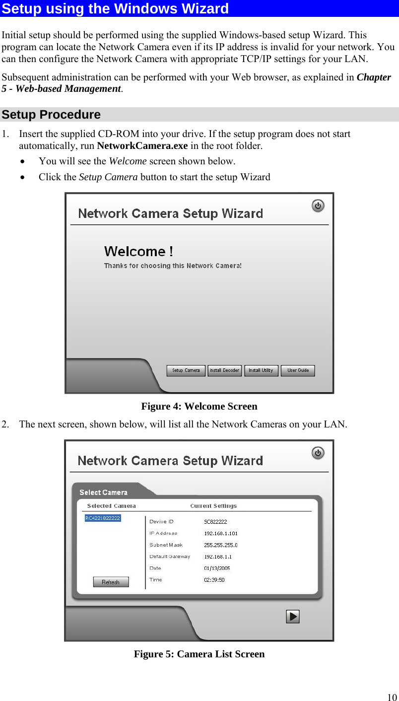
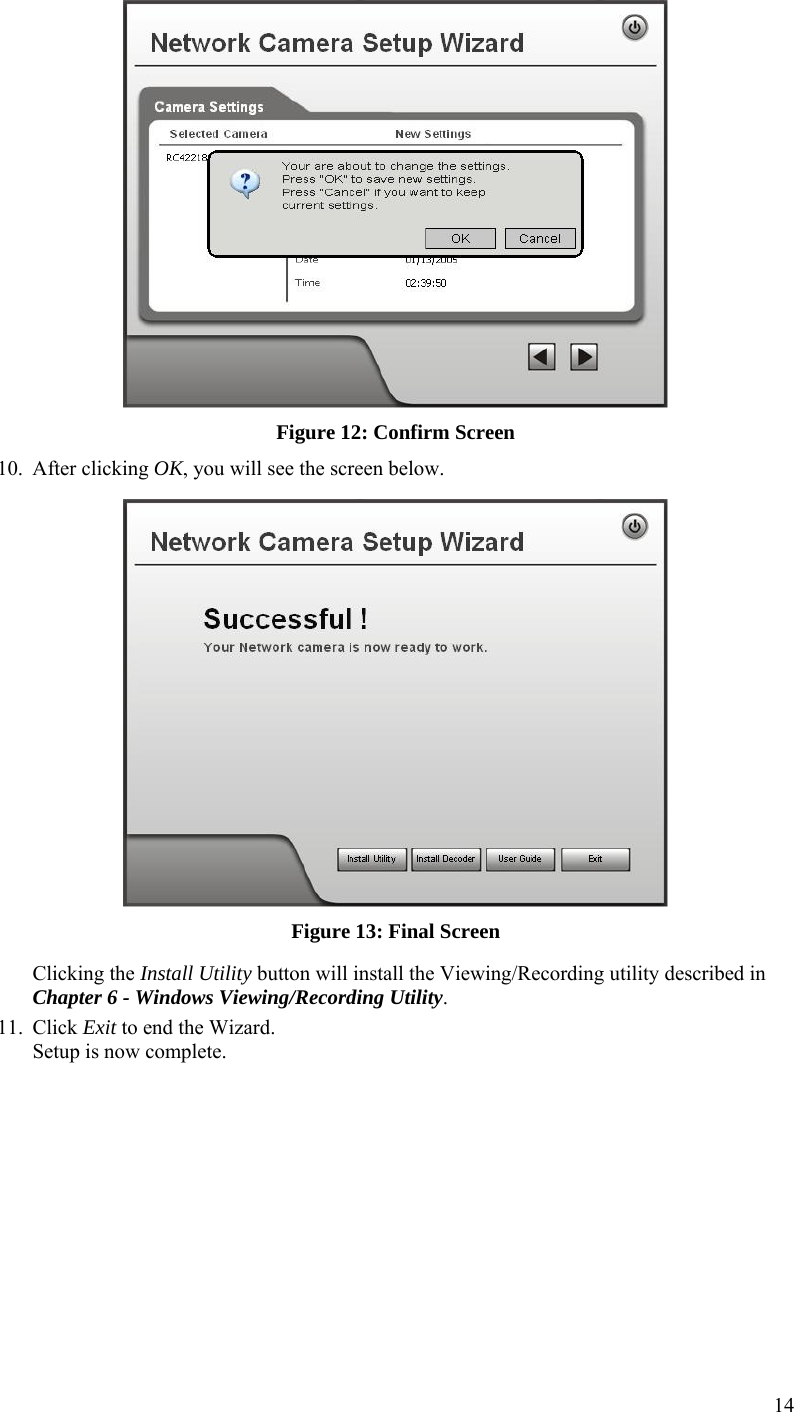
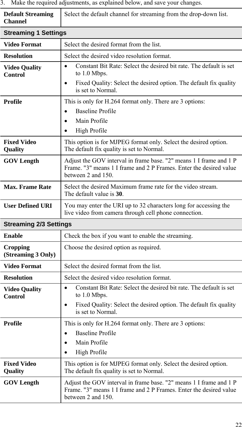
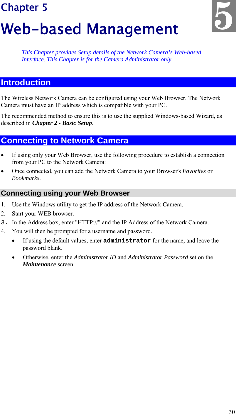
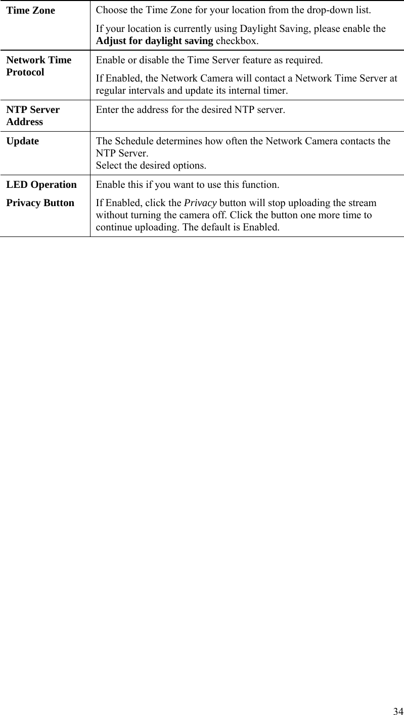
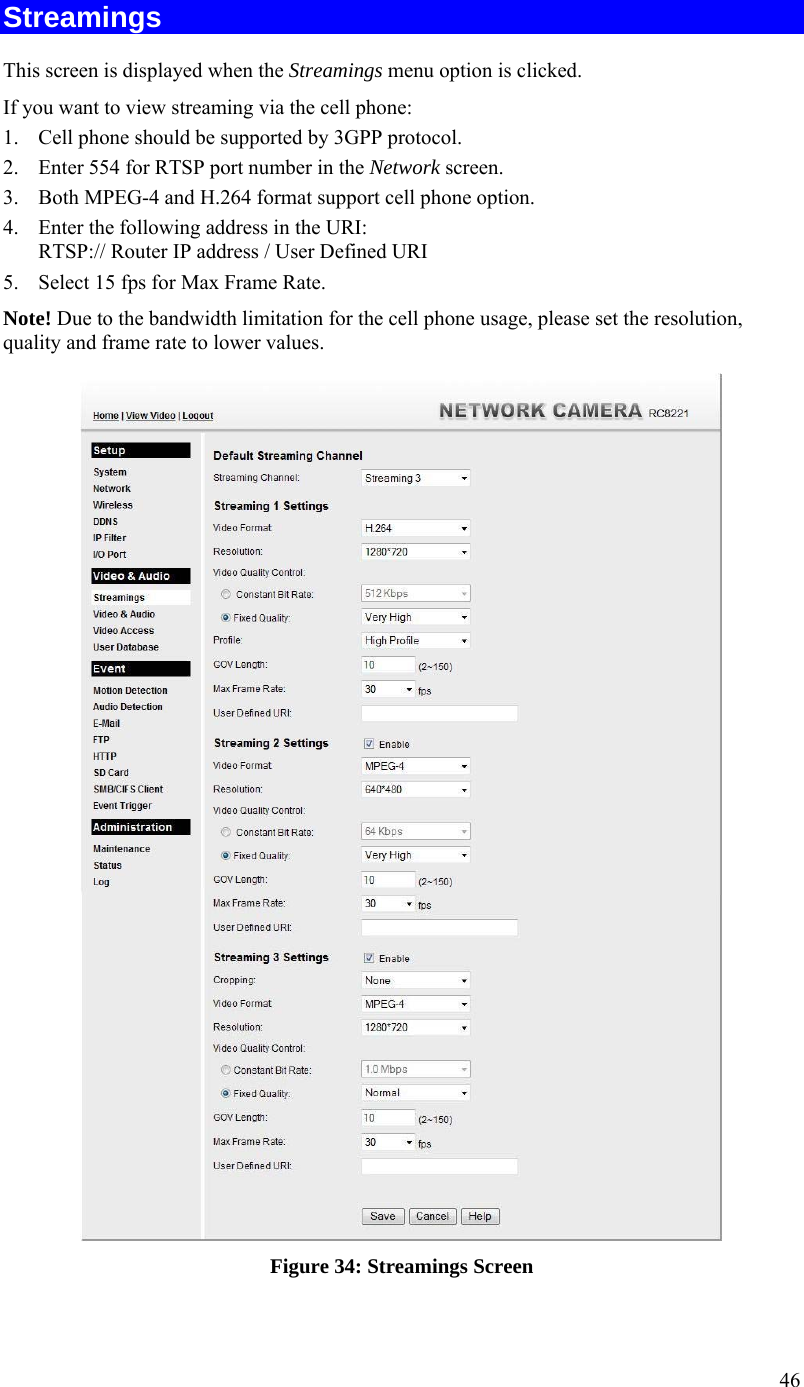
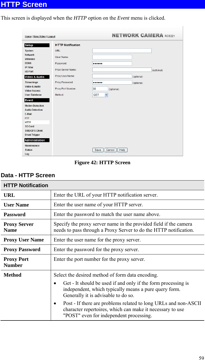
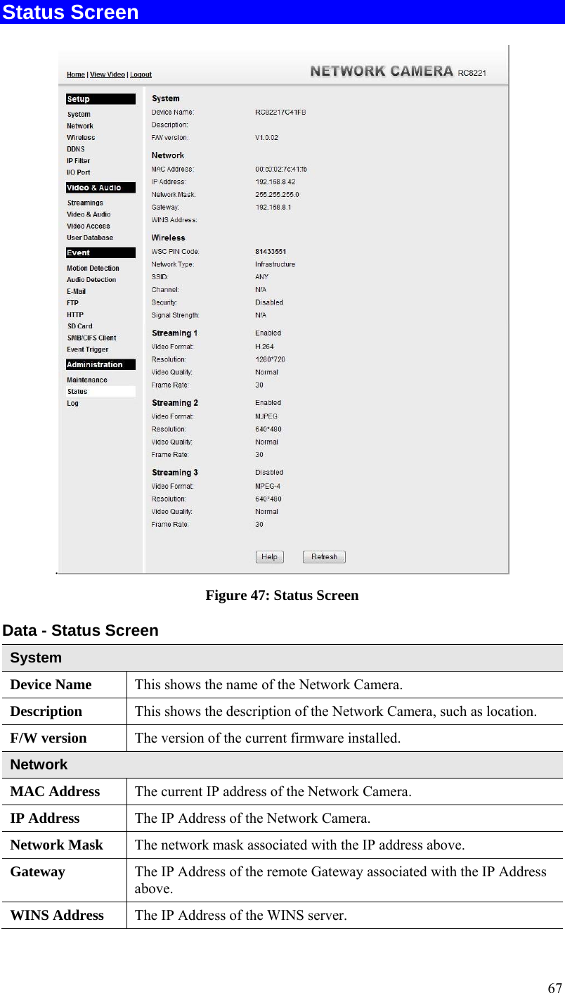
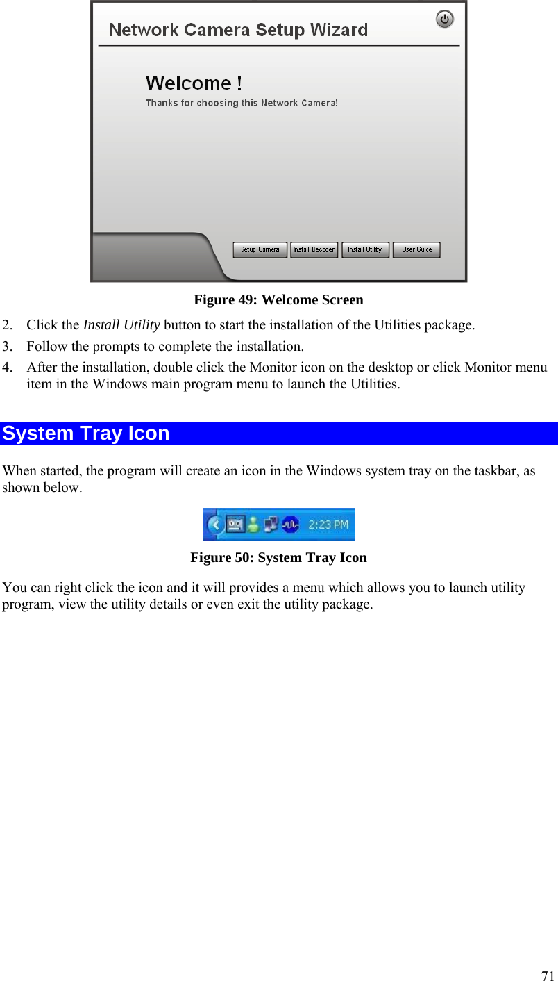
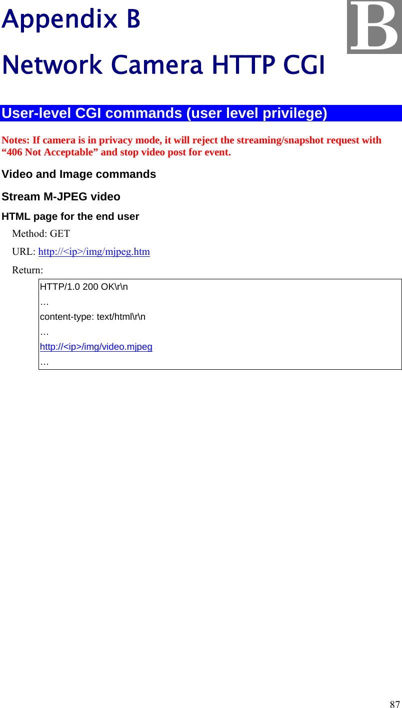
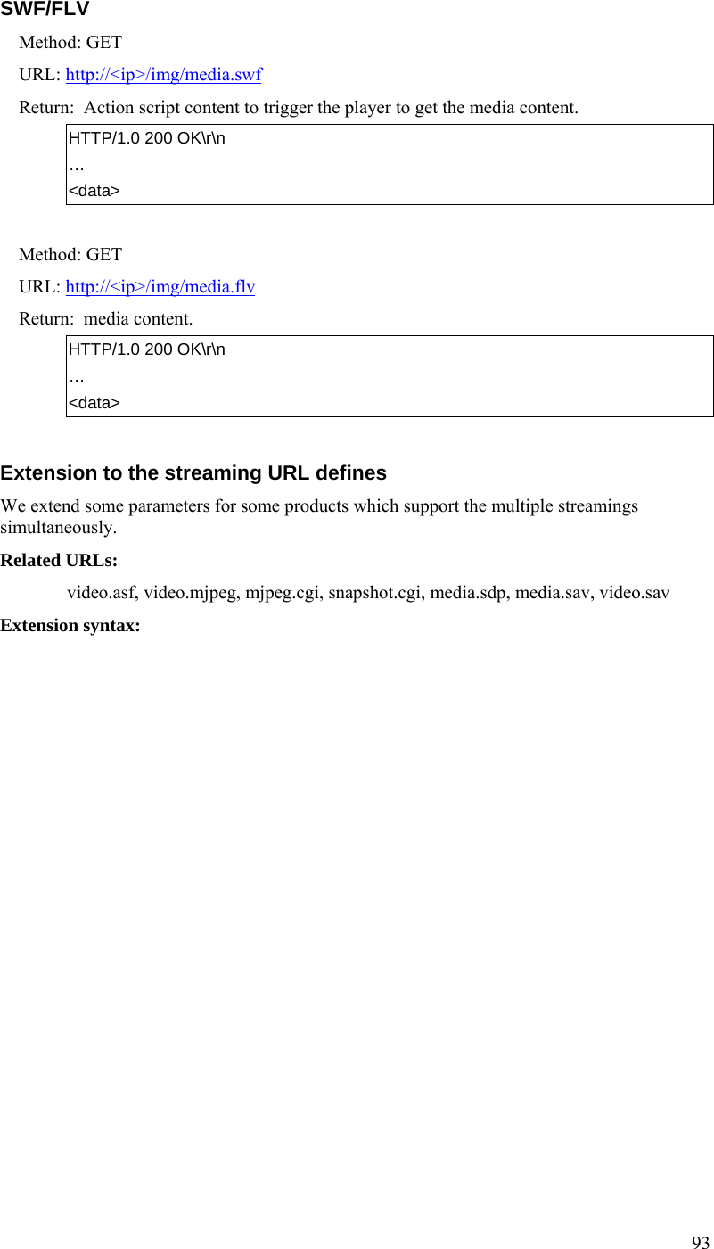
![91 … content-type: image/jpeg\r\n … <JPEG image data> SDP (MPEG-4/H.264 video/MJPEG) Method: GET URL: http://<ip>/img/media.sdp Return: A SDP file will be returned. HTTP/1.0 200 OK\r\n … <SDP data> Audio Upload (uploading audio streaming to the camera) Method: POST URL: http://<ip>/img/g726.cgi G.726 audio stream (16Kbps or 32Kbps, depends on models) URL: http://<ip>/img/g711a.cgi G.711 a-law audio stream (64Kbps) URL: http://<ip>/img/g711u.cgi G.711 u-law audio stream (64Kbps) Example (client side): POST /IMG/g726.cgi HTTP/1.0\r\n Host: 192.168.0.99\r\n Return: OK HTTP/1.0 200 OK\r\n Client starts to upload the audio stream. Unauthorized (Bad username, password) HTTP/1.0 401 Unauthorized\r\n RTP/RTSP User can stream video and audio through the following URLs. Video and audio: rtsp://<ip>/img/media.sav Video only: rtsp://<ip>/img/video.sav Audio only: rtsp://<ip>/img/audio.sav If the client player is QuickTime player, there are always around 3 seconds latency. If there is not audio content in the streaming, you can use the extension parameter “[?|&]latency=no” to push QuickTime player to play the streaming without any latency, but this method causes the frame rate is not stable. Example: rtsp://<ip>/img/video.sav?latency=no](https://usermanual.wiki/Sercomm/RC8221V2/User-Guide-2438184-Page-94.png)
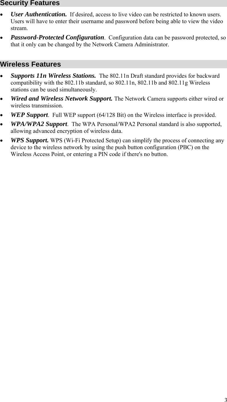
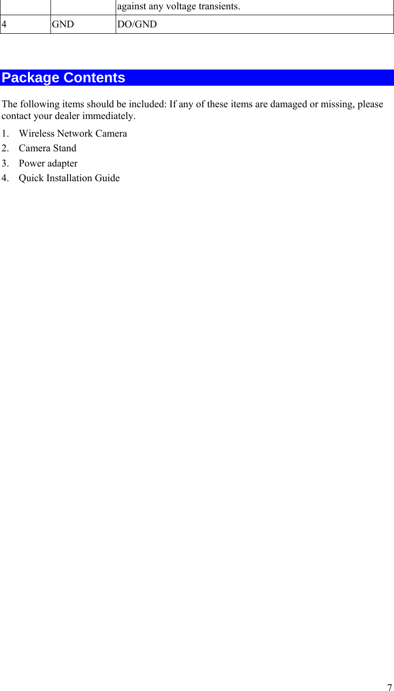
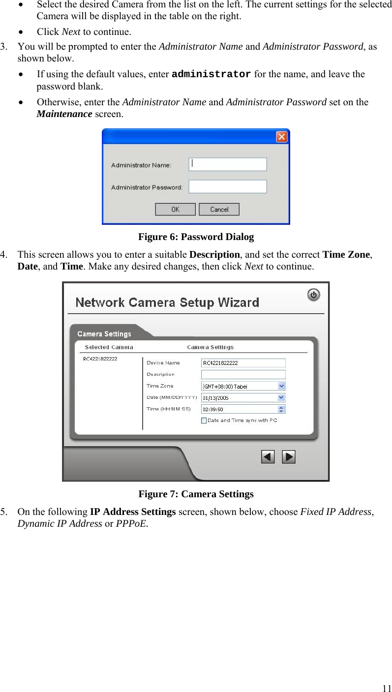
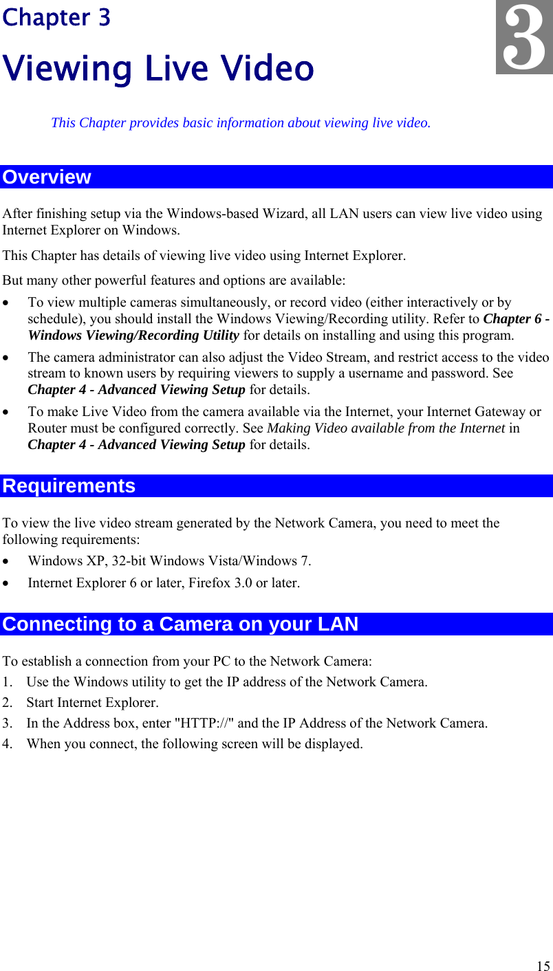
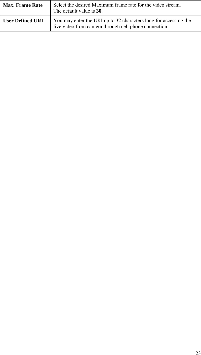
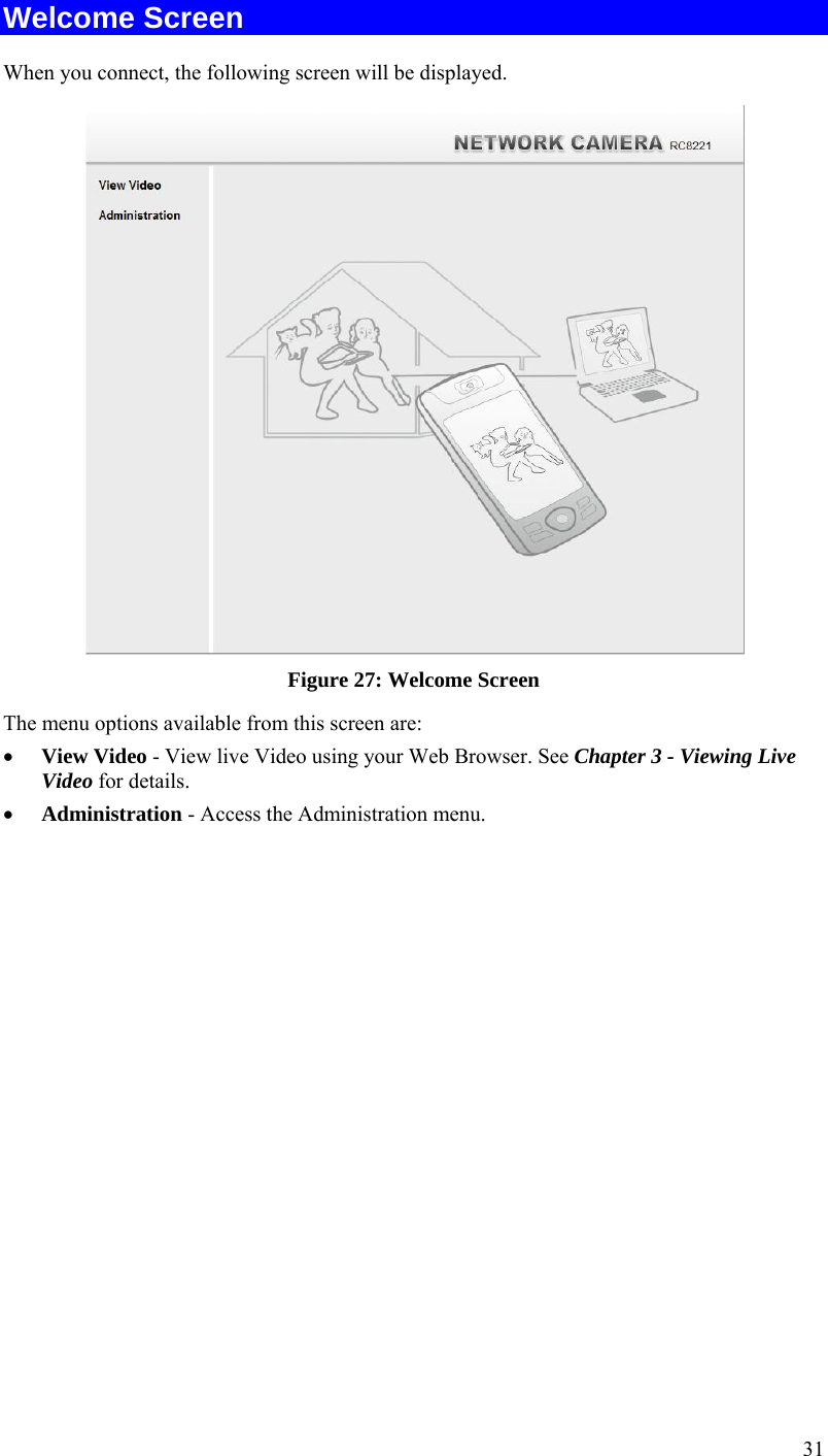
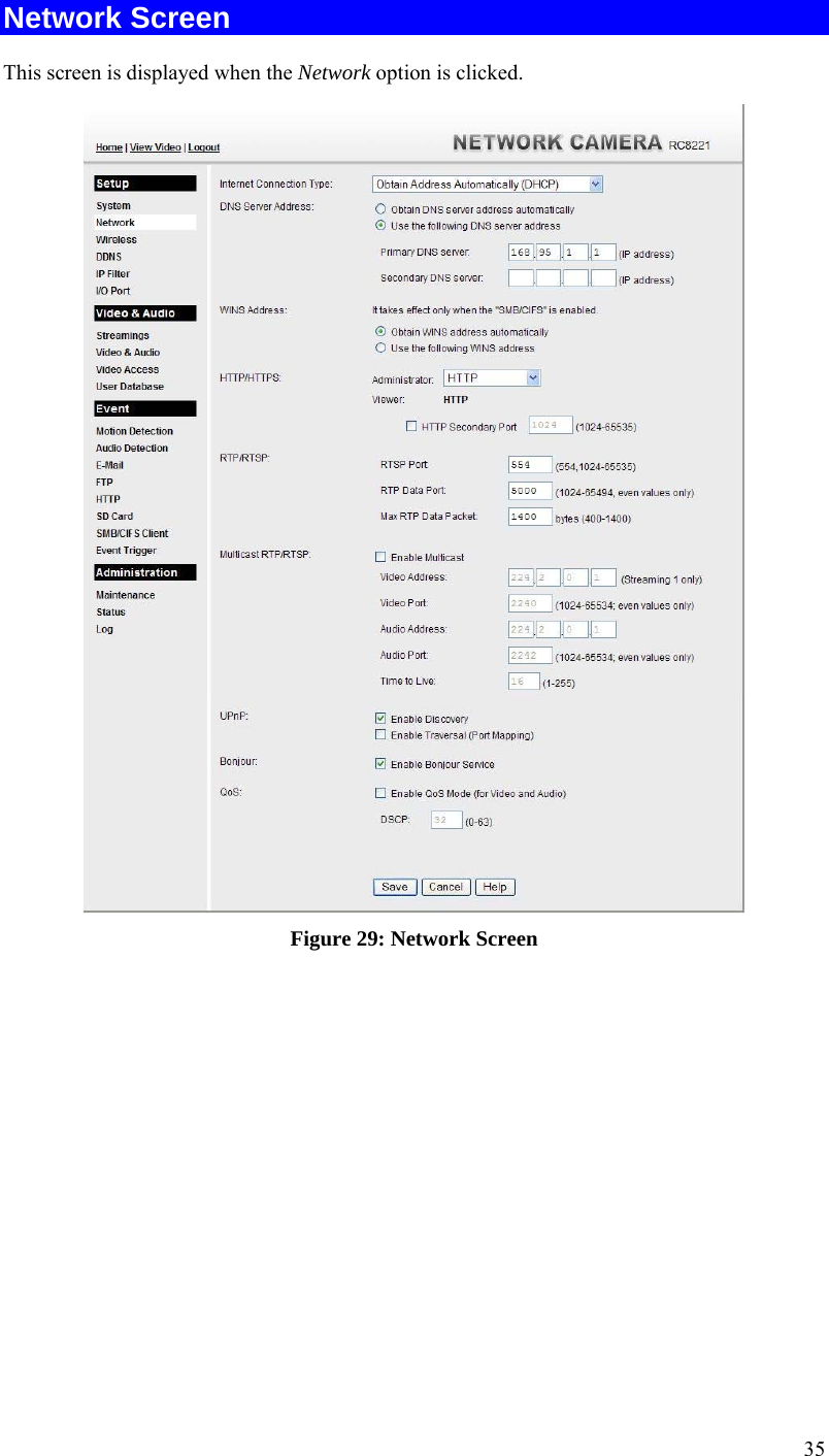
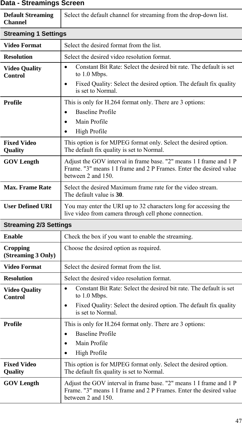
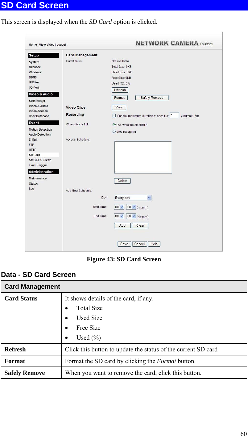
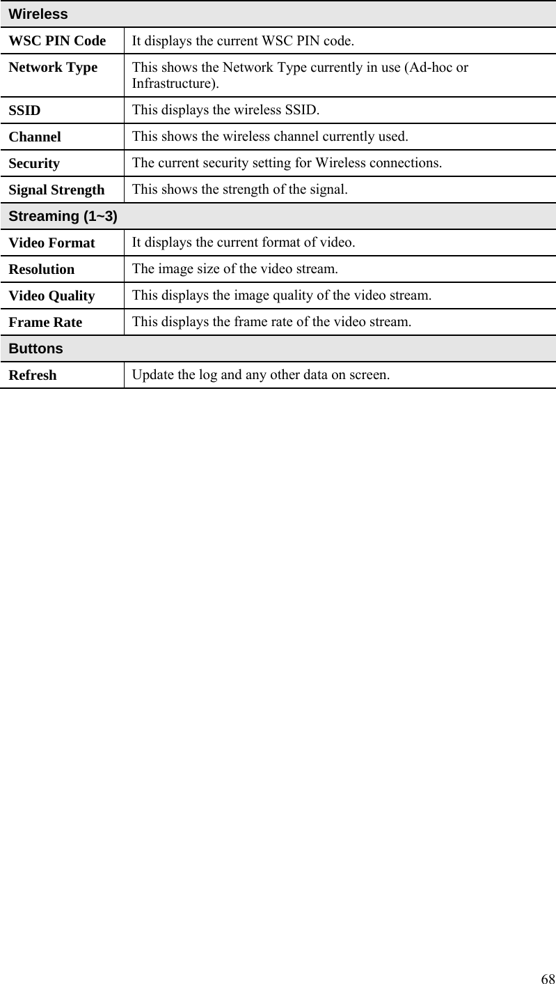
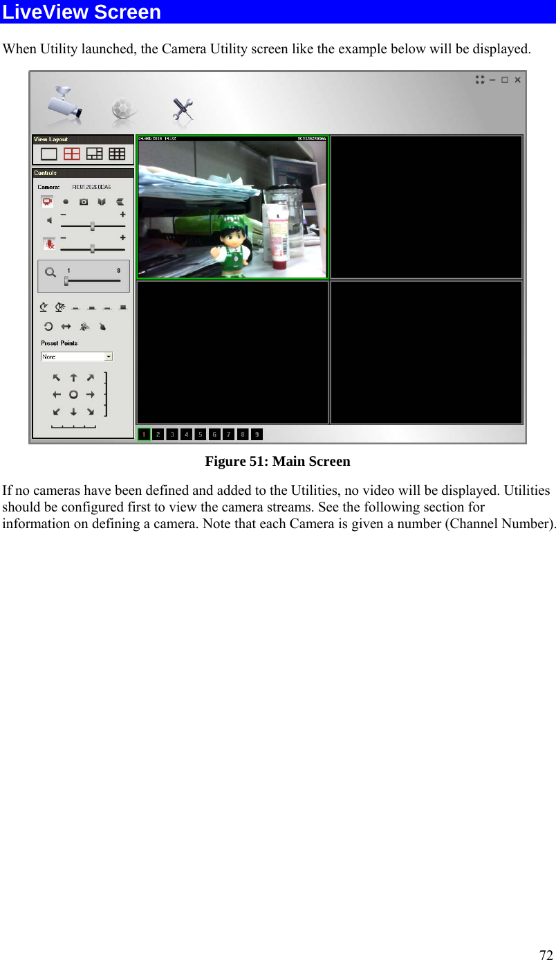
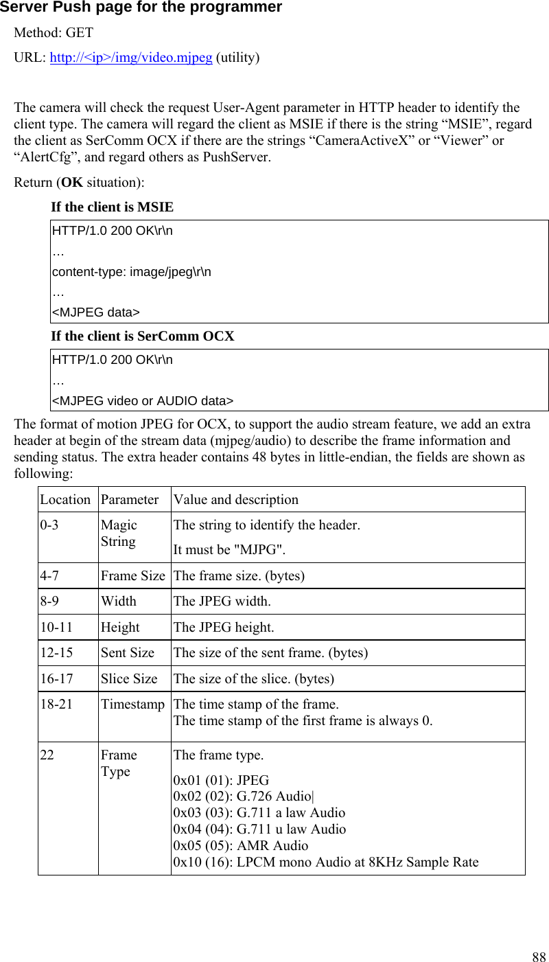
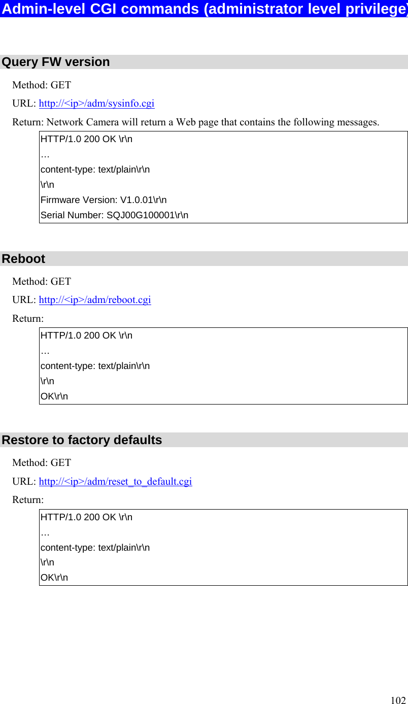
![94 Parameter Description channel If the product supports multiple streaming channels simultaneously, we will append the parameter “[?|&]channel=[1|2|...]” to identify, example: To view the 1st channel streaming: video.sav or video.sav?channel=1 To view the 2nd channel streaming: video.sav?channel=2 video If the product supports multiple video codec simultaneously, we will append the parameter “[?|&]video=[MPEG4|MJPEG|H264]” at the end of original URL to identify, example: To view streaming with MPEG4 video: video.sav?video=MPEG4 To view streaming with H264 video: video.sav?video=H264 Mix the parameters channel and video If the product supports multiple streaming channels and multiple video codec at one video channel simultaneously, we will append both channel and video parameters to identify, the parameter “channel” is the main key with priority. Response error if parameters are not correct. If only “channel” parameter provided, stream the default video, priority is: MPEG4, MJPEG, H264. If none parameter provide, use the default channel number, and then stream the video by priority channel 1,2,3… If only “video” parameter provided, stream the video from the channel supports, use the default channel number, and then priority is: 1,2,3,… Example#1: Total is 3 channels, the 1st channel has H264 video and the 2nd channel has MPEG4 video, the 3rd channel has MJPEG video, default viewer channel is 1st, then: To view the H264 (or to view the 1st channel video): video.sav?channel=1 or video.sav?video=H264 or video.sav?channel=1&video=H264 To view the MPEG4 (or to view the 2nd channel video): video.sav?channel=2 or video.sav?video=MPEG4 or video.sav?channel=2&video=MPEG4 To view the MJPEG (or to view the 3rd channel video): video.mjpeg Example#2: Total is 3 channels, the 1st channel has H264 video](https://usermanual.wiki/Sercomm/RC8221V2/User-Guide-2438184-Page-97.png)
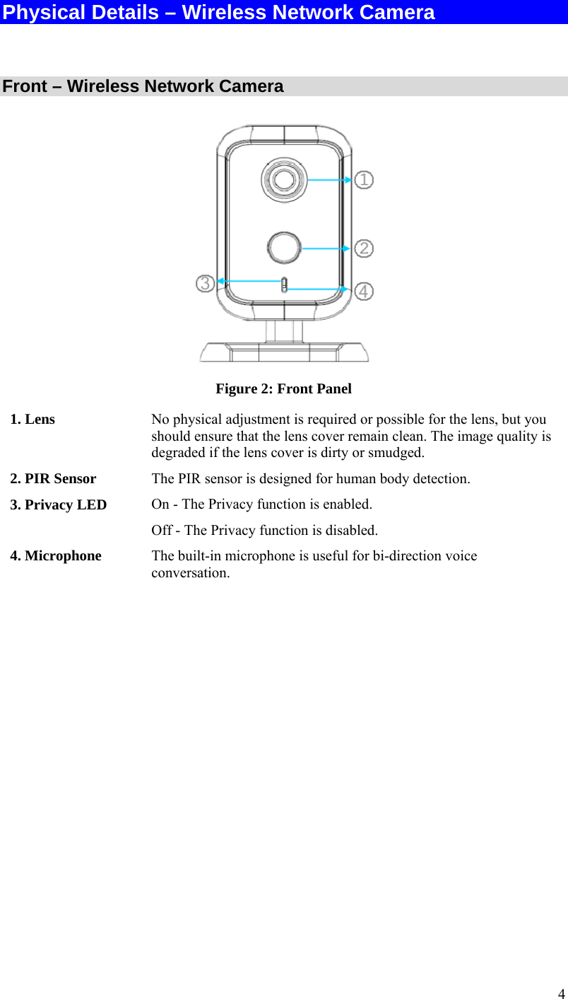
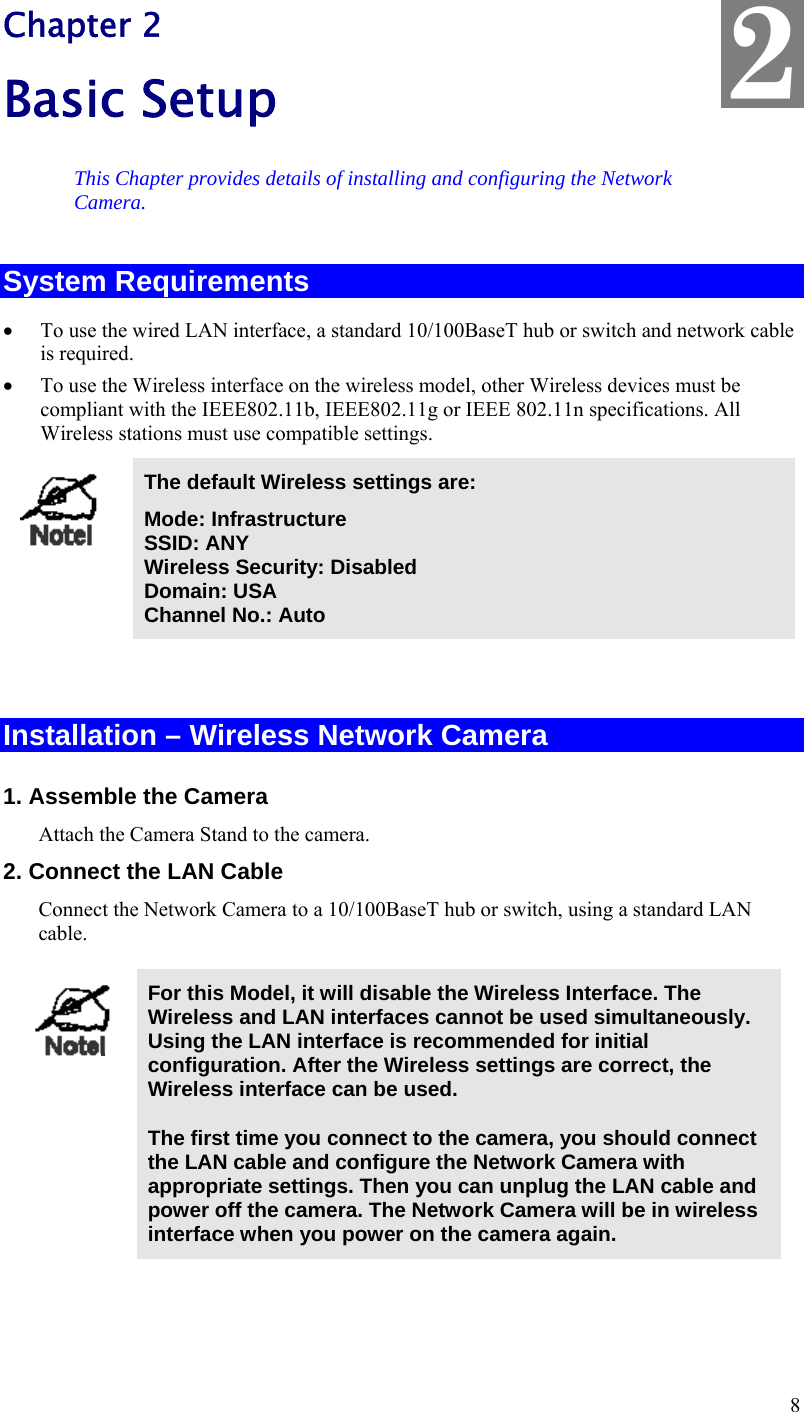
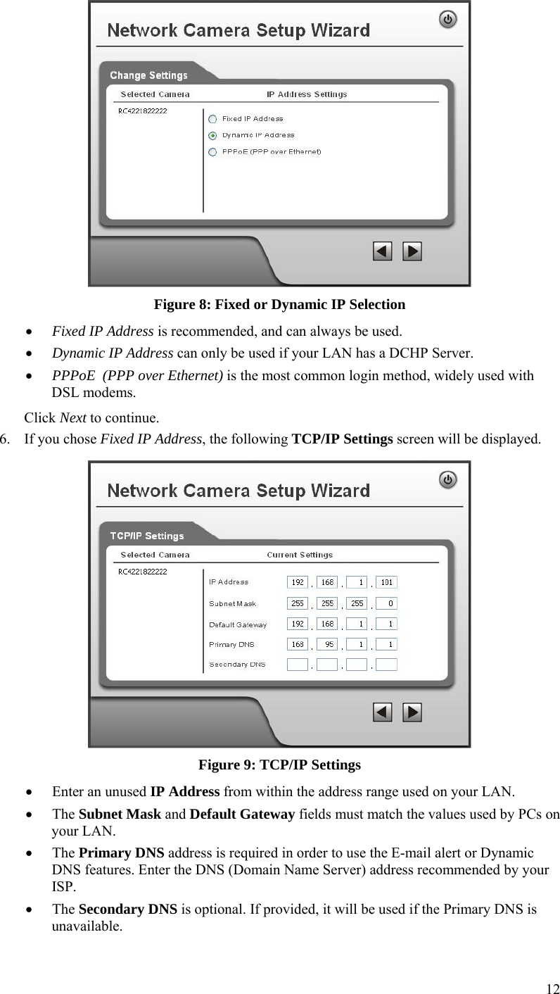
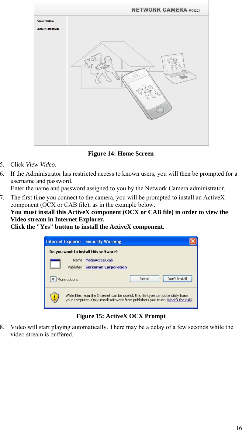
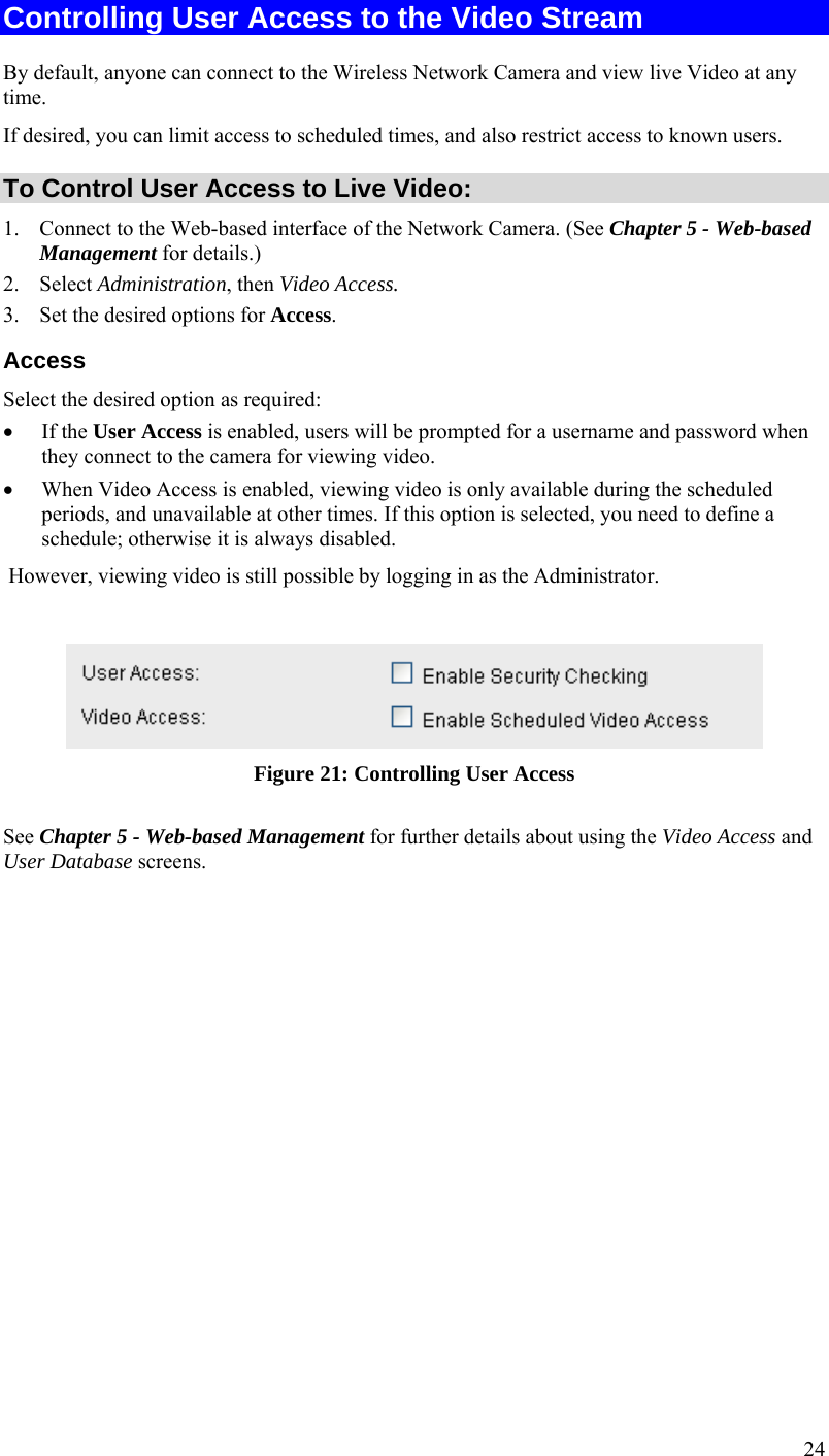
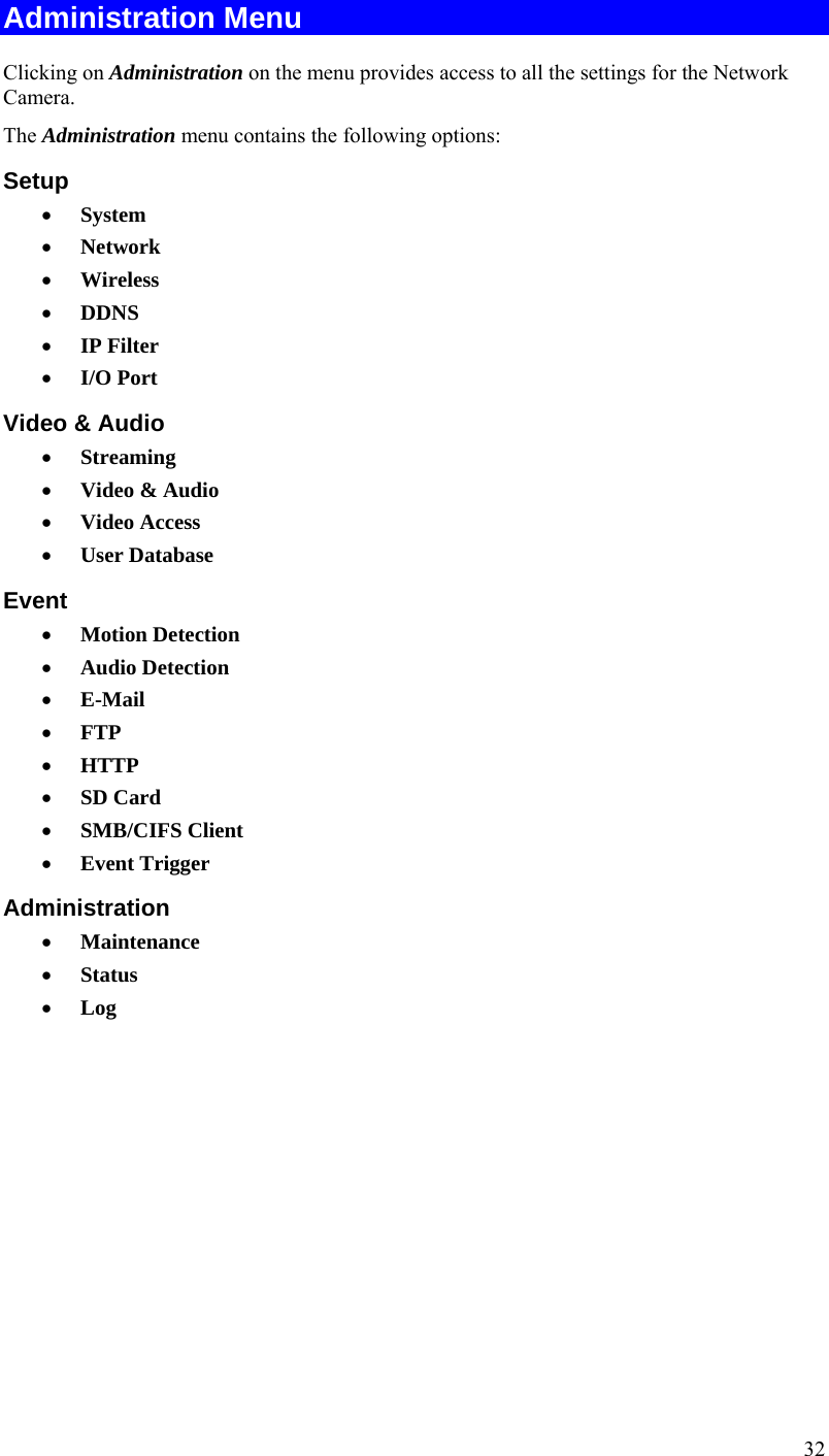
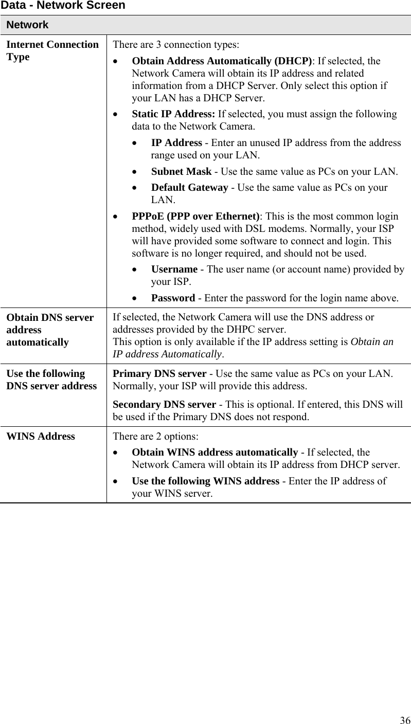
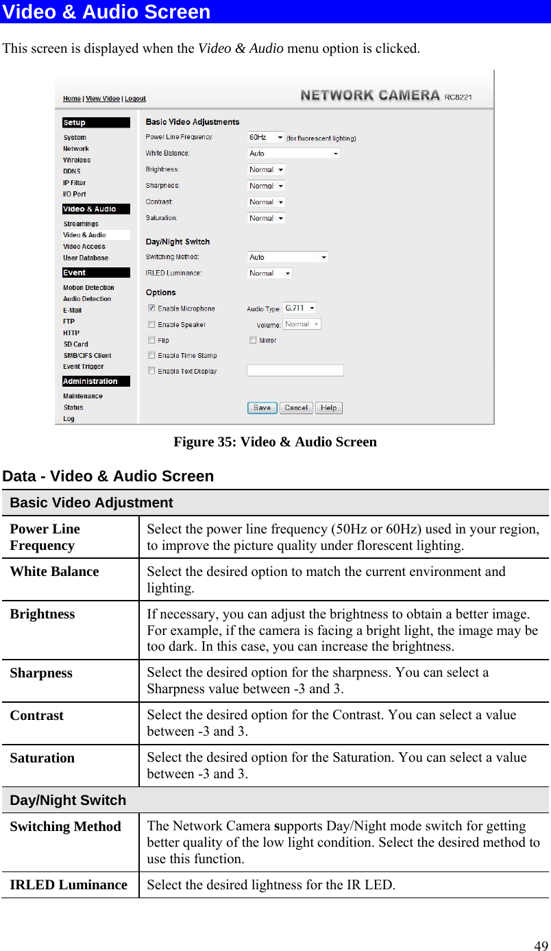
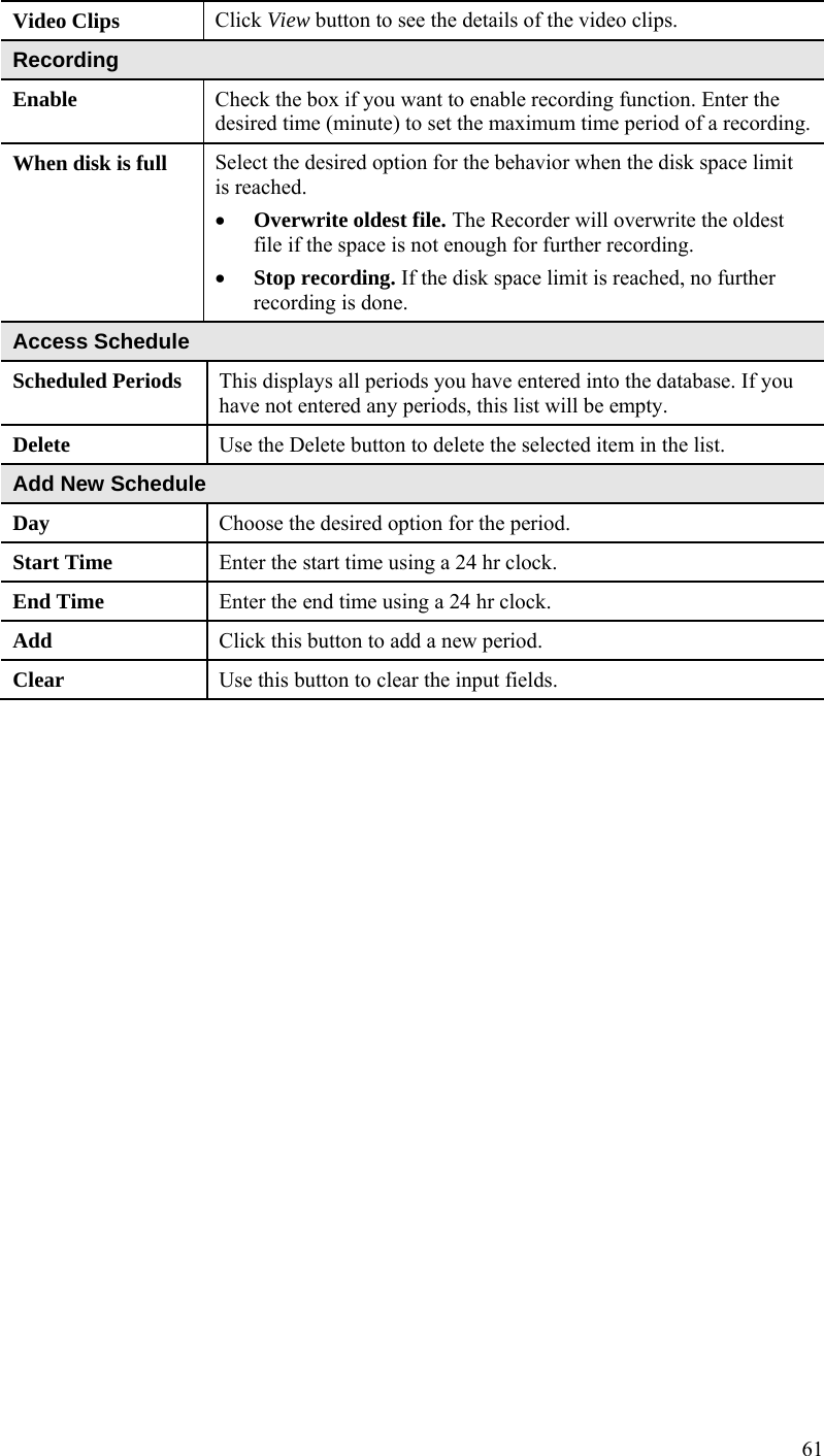
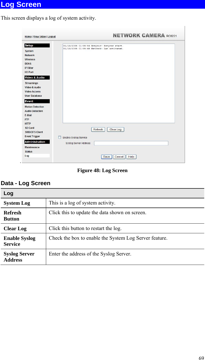
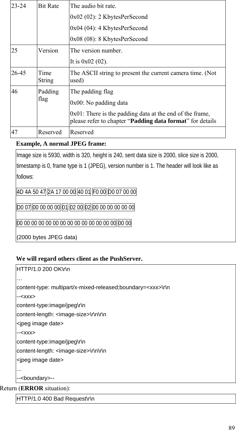
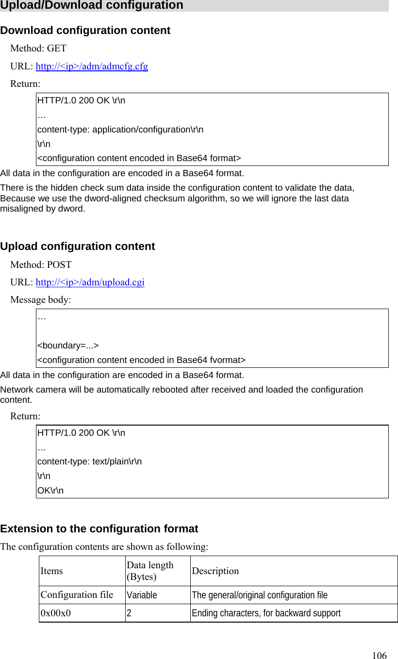
![95 and the 2nd channel has H264 video, the 3rd channel has MJPEG video, default viewer channel is 1st, then: To view the H264 at 1st channel: video.sav?channel=1&video=H264 or video.sav?video=H264 To view the H264 at 2nd channel: video.sav?channel=2&video=H264 Have not MPEG4 video for viewing. To view the MJPEG: video.mjpeg Example#3 (not supported in product spec yet): Total is 2 channels, the 1st channel has H264 video and the 2nd channel has H264 & MPEG4 videos, default viewer channel is 1st, then: To view the H264 at 1st channel: video.sav?channel=1&video=H264 To view the H264 at 2nd channel: video.sav?channel=2&video=H264 To view the MPEG4 at 2nd channel: video.sav?channel=2&video= MPEG4 or video.sav?video=MPEG4 padding If the product supports padding data over the streaming, such as motion information, we will append the parameter “[?|&]padding=[no|yes]” to identify, default (no this parameter) depends on products and streaming types. Example: To view the streaming without padding data: video.sav?padding=no To view the streaming with padding data: video.sav?padding=yes * You can refer to the section 2.11 for more details. Player commands Query Method: GET URL: http://<ip>/util/query.cgi[?extension=value] This CGI indicates the H/W capability, component setting. Ex: The camera got I/O port (or not). The camera got Speaker (or not), etc.](https://usermanual.wiki/Sercomm/RC8221V2/User-Guide-2438184-Page-98.png)
![96 Parameter Value and description extension Extension value yes: extension is enabled, the extended data as below will be extended to generic response. fw_ver=V1.0.0R44\r\n ip_addr=192.168.1.12\r\n netmask=255.255.255.0\r\n gateway=192.168.1.1\r\n current_time=07/02/2008 10:12:10\r\n -> MM/DD/YYYY HH:MM:SS 24-Hour format timezone=4\r\n http_port=80\r\n -> The value is -1 or none this parameter indicate the HTTP disabled. https_port=443\r\n -> The value is -1 or none this parameter indicate the HTTPS disabled. rtsp_port=554\r\n Return: HTTP/1.0 200 OK \r\n … content-type: text/plain\r\n \r\n <parameter pair>\r\n <parameter pair>\r\n ...... Here are the details of parameter pairs: Parameter Value and description hostname Camera name, example: sc123456 description Camera description, example: Hello camera defname Camrea default name, example: default name mac Camera's MAC address, example: 00C002123456 company_name Camera's comany name, example: SerComm model_number Camera's model number, example: RC8020 resolutions Phase out in new projects. The resolutions camera support, depends on models, valid values: [1280*960,640*480,320*240,160*120|704*480,352*240,176*120|704*576,352*288,176*144]](https://usermanual.wiki/Sercomm/RC8221V2/User-Guide-2438184-Page-99.png)
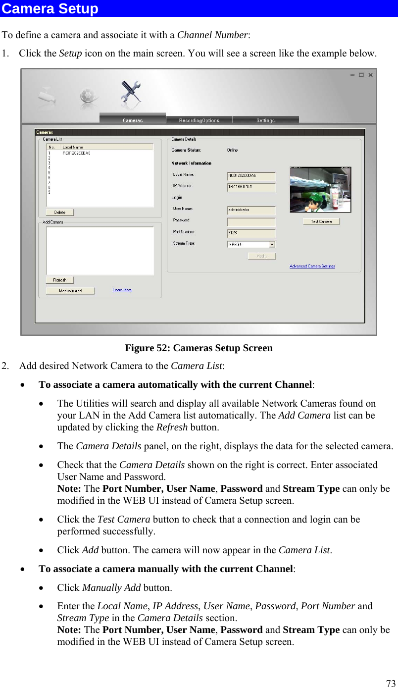
![97 mpeg4_resolution Current MPEG-4 resolution setting, depends on models, valid values: [1280|640|320|160|704|352|176] For multiple streaming channels, use the keys: mpeg4_resolution, mpeg4_resolution2, … Won't provide this paramter if there is not such video format enabled or supportted. mjpeg_resolution Current JPEG resolution setting, depends on models, valid values: [1280|640|320|160|704|352|176] For multiple streaming channels, use the keys: mjpeg_resolution, mjpeg_resolution2, … Won't provide this paramter if there is not such video format enabled or supported. h264_resolution Current H.264 resolution setting, depends on models, valid values: [1280|640|320|160|704|352|176] For multiple streaming channels, use the keys: h264_resolution, h264_resolution2, … Won't provide this paramter if there is not such video format enabled or supported. mic_in Current MIC in setting, valid values: [on|off] speaker_out Current Speaker out setting, valid values: [on|off] audio_duplex_mode Only valid for the products have such setting feature in Web UI. Current audio duplex mode setting, only “off” is valid, example: Talk only: mic_in=off, speaker_out=on Listen only: mic_in=on, speaker_out=off Talk & Listen duplex: mic_in=on, speaker_out=on Talk & Listen half: mic_in=on, speaker_out=on, audio_duplex_mode=off ptctrl PT HW capability, valid values: [on|off] ioctrl IO HW capability, valid values: [on|off] serial RS485 capability, valid values: [pelco|off] privacy_button Privacy button HW capability, valid values: [on|off] pir_sensor PIR sensor HW capability, valid values: [on|off] wlled White light LED HW capability, valid values: [on|off] irled IR LED HW capability, valid values: [on|off] wps_pin_code WPS PIN code value, example: 00000048](https://usermanual.wiki/Sercomm/RC8221V2/User-Guide-2438184-Page-100.png)
![98 wireless Wireless HW capability, example: [on|off] sw_pppoe PPPoE software feature capability/supported, valid values: [yes|no] URL: http://<ip>/img/query.cgi This CGI indicates the accessed user's privilege with some H/W features. Ex. The user could use Speaker Out, but couldn't control the I/O ports, etc. Return: HTTP/1.0 200 OK \r\n … content-type: text/plain\r\n \r\n mic_in=[on|off]r\n speaker_out=[on|off]\r\n ptctrl=[on|off]\r\n ioctrl=[on|off]\r\n interlace=[0|1]\r\n(only for analog CCTV input)](https://usermanual.wiki/Sercomm/RC8221V2/User-Guide-2438184-Page-101.png)
![99 Query/Control the peripheral components status (Operator, combination CGI) Notes: This combination CGI command will replace the separated peripheral control CGIs. Query the peripheral components status Method: GET URL: http://<ip>/io/query_pc.cgi[?<parameter>[&<parameter>...]] Input parameters: None parameter provided, CGI responds all supported peripherals' status. The peripheral parameter provided, CGI just responds the specific peripherals' status. Please refer to the “Parameter Pairs Table” for specific input parameters. Return: HTTP/1.0 200 OK \r\n … content-type: text/plain\r\n \r\n <parameter pair>\r\n <parameter pair>\r\n ...... Here are the details of parameter pairs, parameters depend on product models. “error” value response indicate that “Failed to query/control the peripheral equipments” Parameter Pairs Table Parameter Get/Set Value and description privacy_button Query only Privacy button status, valid values: [disabled|off|on] pir Query only PIR status, valid values: [disabled|actionless|active] light_sensor Query only Light sensor status, valid values: [disabled|night|day] pt_position Query only Query current Pan & Tilt position, because the MCU can’t get response from PT, so the values maybe wrong under some conditions. Format is “X,Y” “X” is the Pan position; “Y” is the Tilt position. input_1 input_2 Query only Input #1,#2 status, valid values: [high|low] output_1 output_2 Get & Set Onput #1,#2 status, Query format is “A,B”. “A” valid values: [high|low] “B” valid values: [pulse|static] Control format is “A”. “A” valid values: [high|low]](https://usermanual.wiki/Sercomm/RC8221V2/User-Guide-2438184-Page-102.png)
![100 dn_mode Get & Set Day/Night mode status, valid values: [day|night] Day mode, IR LED off, IR cut switch close the window to filter the IR lights. Night mode, IR LED on, IR cut switch open the window not to filter the IR lights. ir_cut Get & Set IR cut switch status, valid values: [close|open] ir_leds Get & Set IR LEDs status, valid values: [disabled|off|on], disabled is only valid for query CGI wl_leds Get & Set White light LEDs status, valid values: [disabled|off|on], disabled is only valid for query CGI Control the peripheral components status Method: GET URL: http://<ip>/io/control_pc.cgi?<parameter>=<value>[&<parameter pair>…] Parameter Value and description Please refer to the “Parameter Pairs Table” Return: Successful request returns all group parameters or the specified parameters as below. HTTP/1.0 200 OK\r\n … content-type: text/plain\r\n ... \r\n OK\r\n](https://usermanual.wiki/Sercomm/RC8221V2/User-Guide-2438184-Page-103.png)
![101 Query IR cut switch status Method: GET URL: http://<ip>/io/query_filter.cgi Return: Network Camera will return a Web page that contains the following messages. HTTP/1.0 200 OK \r\n … content-type: text/plain\r\n \r\n filter=[0|1]\r\n <- 0= Close the window; 1= Open the window \r\n](https://usermanual.wiki/Sercomm/RC8221V2/User-Guide-2438184-Page-104.png)
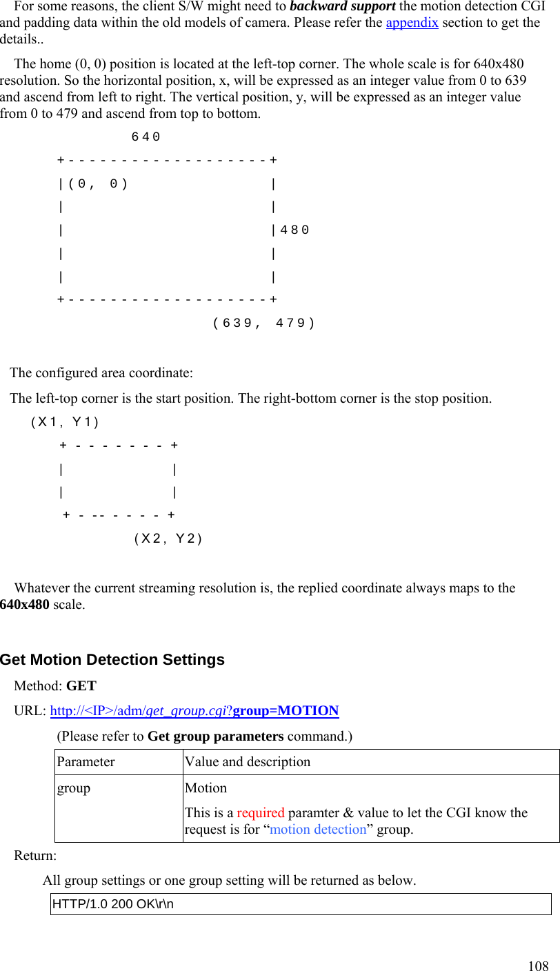
![103 Query/Control the peripheral components status Start/Stop the camera privacy mode Method: GET URL: http://<ip>/adm/privacy_ctl.cgi?privacy=<parameter> Parameter Value and description start start: camera enter privacy mode. Any user can't view the video any more. stop stop: camera end the privacy mode. Return: Successful request returns all group parameters or the specified parameters as below. HTTP/1.0 200 OK\r\n … content-type: text/plain\r\n ... \r\n OK\r\n Get/Set group parameters Get group parameters Method: GET URL: http://<ip>/adm/get_group.cgi?<parameter>=<value>[&<value>…] Parameter Value and description group 1. To get all group settings group_name (The group name is case insensitive.) 2. To get a specific setting from a group group_name.parameter_name 3. To get the settings from multiple groups group_name&group_name... Note that all group_name and parameter_name are defined in the Network Camera Configuration Spec Return: All group settings or one group setting will be returned as below. HTTP/1.0 200 OK\r\n … content-type: text/plain\r\n](https://usermanual.wiki/Sercomm/RC8221V2/User-Guide-2438184-Page-106.png)
![104 ... \r\n [group1]\r\n <parameter pair>\r\n <parameter pair>\r\n ...\r\n [group2]\r\n <parameter pair>\r\n <parameter pair>\r\n ...\r\n Where <parameter pair> is <parameter_name>=<parameter_value>. Set group parameters Method: GET URL: http://<ip>/adm/set_group.cgi?<parameter>=<value>[&<parameter pair>…] Parameter Value and description group Group name is specified here. (The group name is case insensitive.)Note that all group values are defined in the Network Camera Configuration Spec. 1. To set a specific setting in a group group=group1&key=value... 2. To get the settings from multiple groups group=group1&key=value...&group=group2&key=value... Return: Successful request returns all group parameters or the specified parameters as below. HTTP/1.0 200 OK\r\n … content-type: text/plain\r\n ... \r\n OK\r\n](https://usermanual.wiki/Sercomm/RC8221V2/User-Guide-2438184-Page-107.png)
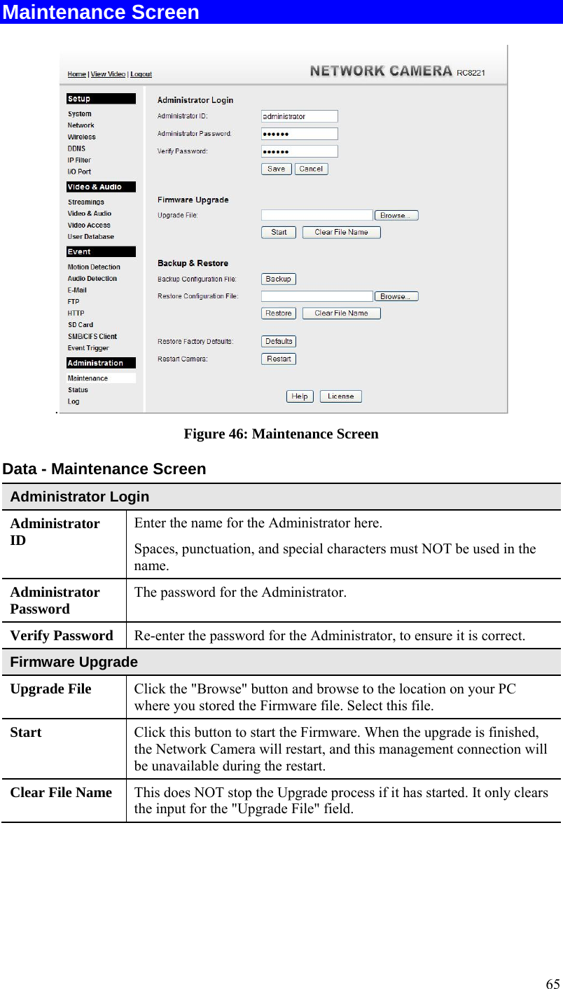
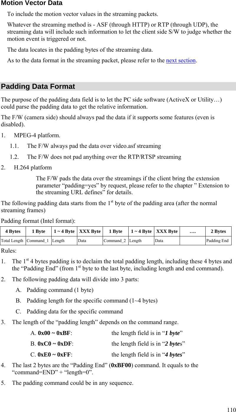
![105 Get/Set System date and time Method: GET URL: http://<ip>/adm/date.cgi?action=<value>[&<parameter pair>…] Parameter Value and description action Get/Set the system date and time get= Get the system date and time set= Set the system date and time time_zone The index value in time zone table (Readonly), please refer to Network Configuration file Spec year Year (2005~2037) month Month (1~12) day Day (1~31) hour Hour (0~23) minute Minute (0~59) second Second (0~59) Return: Successful request returns all group parameters or the specified parameters as below. HTTP/1.0 200 OK\r\n … content-type: text/plain\r\n ... \r\n OK\r\n <parameter pair>\r\n <parameter pair>\r\n ...\r\n Upgrade firmware Method: POST URL: http://<ip>/adm/upgrade.cgi Message body: … … <boundary=...> … <FW binary data> The client must wait as least 5 minutes to make sure all flashes have been programmed. Return: A FW Upgrade Progress window will be returned.](https://usermanual.wiki/Sercomm/RC8221V2/User-Guide-2438184-Page-108.png)
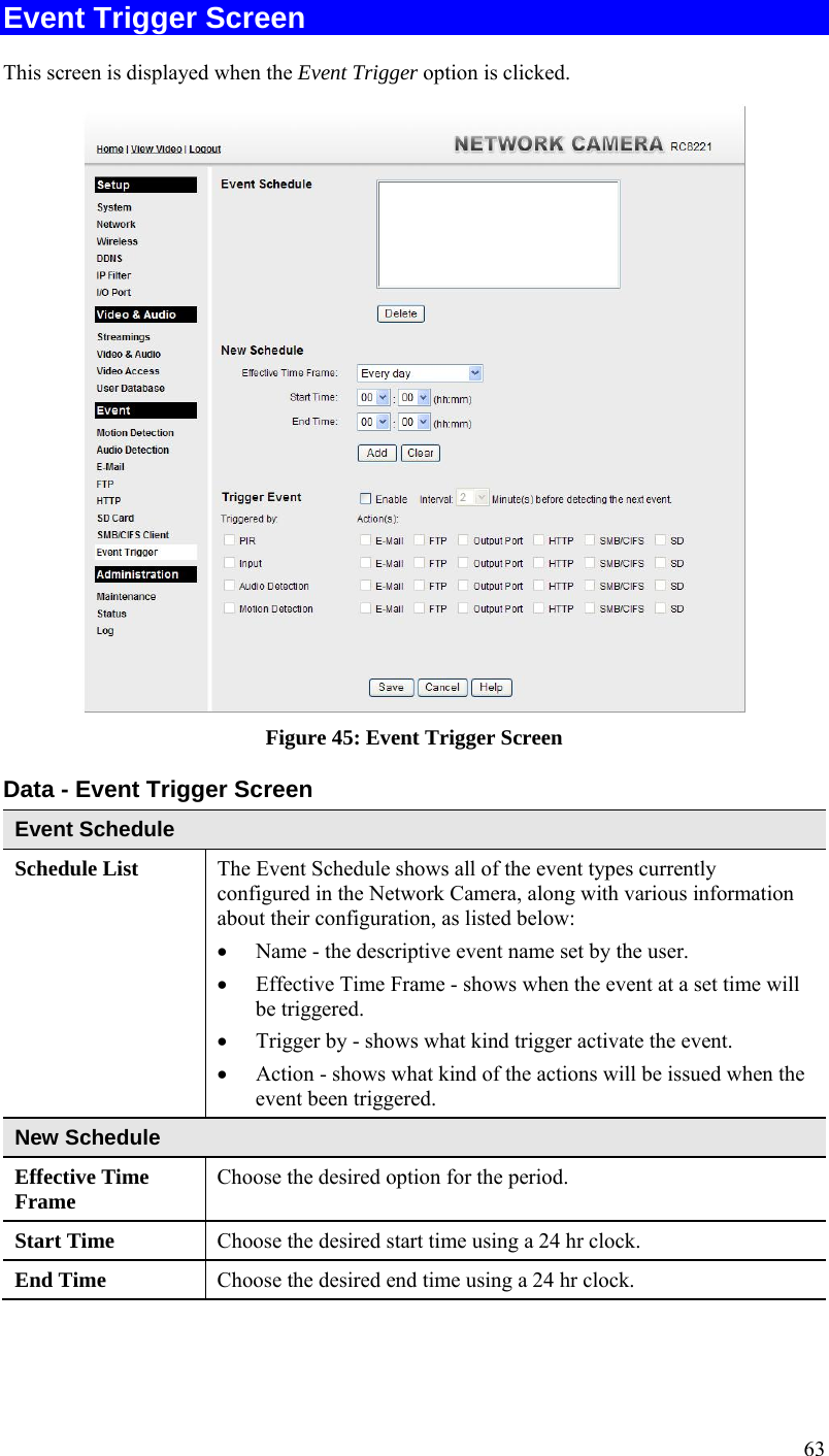
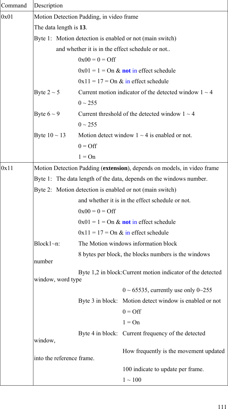
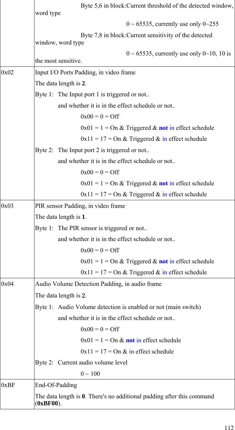
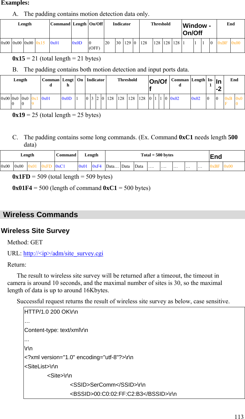
![109 … content-type: text/plain \r\n ... \r\n [MOTION] .... Please refer to the chapter [MOTION] group in Configuration file Spec document. \r\n Set Motion Detection Settings Method: GET URL: http://<IP>/adm/set_group.cgi?group=MOTION&<parameter>=<value>… (Please refer to Set group parameters command and Configuration file Spec document.) Return: HTTP/1.0 200 OK\r\n … content-type: text/plain\r\n \r\n OK\r\n Notes: In some special models (the first motion window is used for full screen), the S/W (OCX) side needs to do it as the following way (without changing any configure item): 1. Use “md_switch1” as the switch of “full screen” or “sub-windows”. 2. The md_window1 always sets to 640x480 size. If “md_switch1=1”, then the camera needs to detect in the whole screen video. The OCX can’t allow the user to configure the rest windows (sub-window 1~3). If “md_switch1=0”, then the camera will detect in the “md_window2~4” area. (It’s the same as the sub-windows 1~3.)](https://usermanual.wiki/Sercomm/RC8221V2/User-Guide-2438184-Page-112.png)
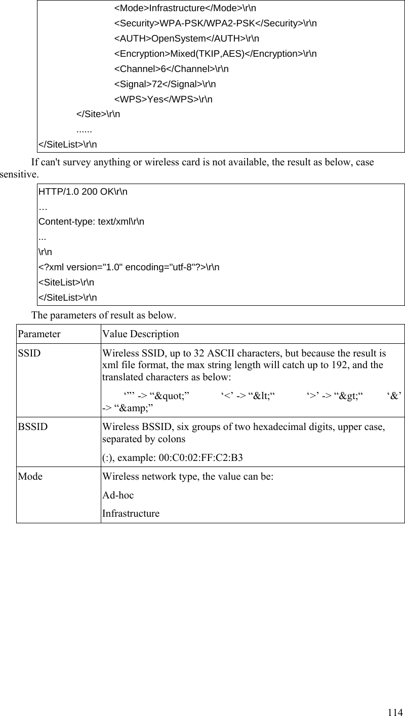
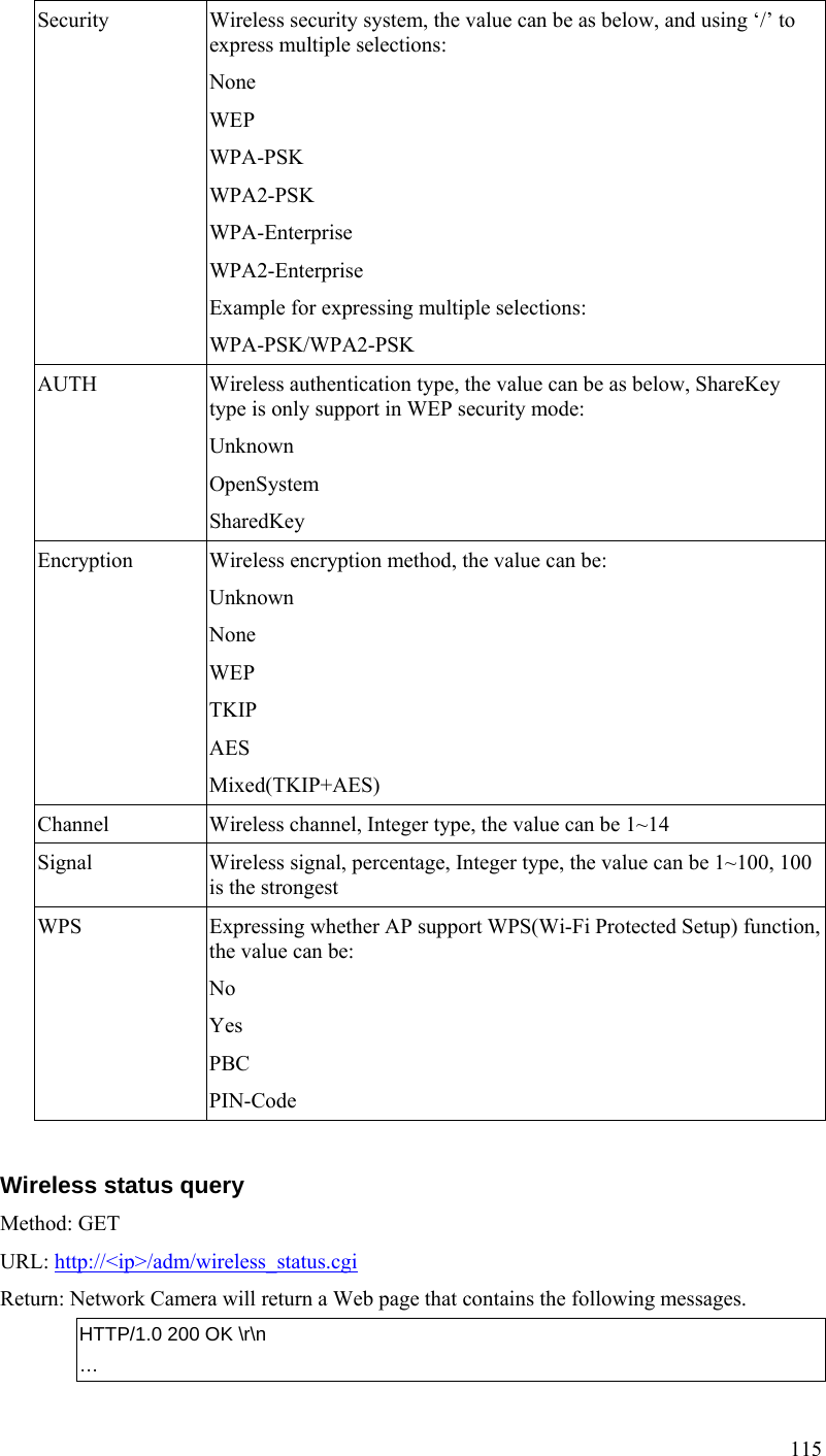
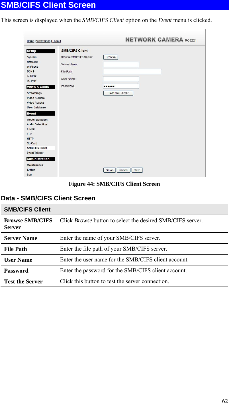
![116 content-type: text/plain\r\n \r\n signal_strength=100\r\n # Wireless signal, percentage, Integer type, the value can be 1~100, 100 is the strongest. \r\n SMB/CIFS Server/SharedFolder commands SMB/CIFS Server Survey Method: GET URL: http://<ip>/adm/smb_survey.cgi[?parameter=value[&parameter=value...]] Parameter Value and description timeout Optional, the timeout in seconds of the cgi, the cgi will stop survey and return the result if timeout, valid values: 5-120, default is 30 action Optional, this CGI will terminate survey action. stop Return: The result will be returned in xml format as following, the content size depends on how many servers in the network. Successful request returns the result of Samba site survey as below, case sensitive. HTTP/1.0 200 OK\r\n … Content-type: text/xml\r\n ... \r\n <?xml version="1.0" encoding="utf-8"?>\r\n <List>\r\n <WorkGroup>\r\n <Name></Name>\r\n <List>\r\n <Server>\r\n <Name></Name>\r\n <Comment></Comment>\r\n </Server>\r\n ... </List>\r\n </WorkGroup>\r\n](https://usermanual.wiki/Sercomm/RC8221V2/User-Guide-2438184-Page-119.png)
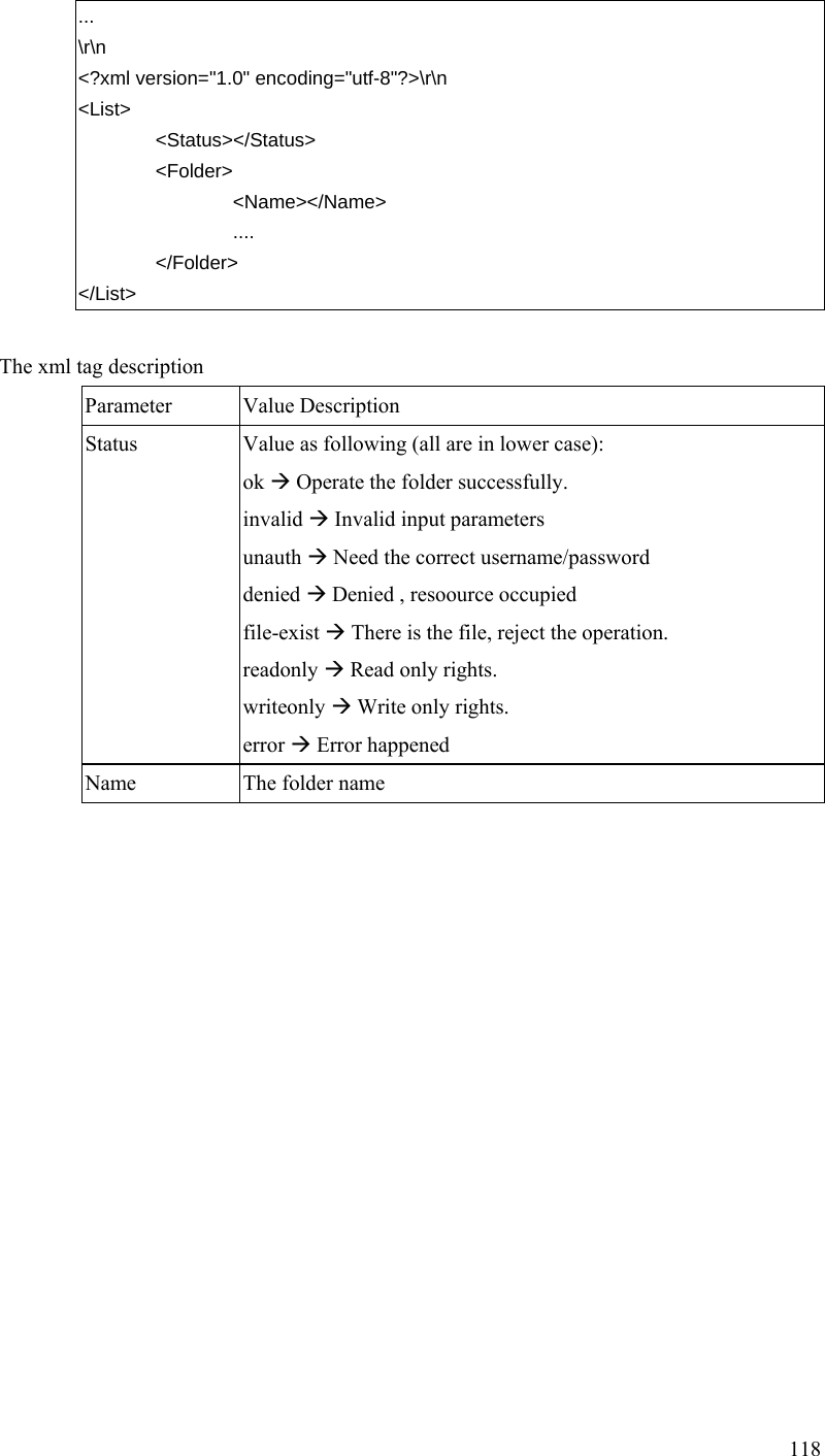
![117 ... </List>\r\n The xml tag description Parameter Value Description Name (WorkGroup) It's the work group name, up to 15 characters. Name (Server) It's the PC name of the server, up to 63 characters. Comment (Server) It's the description of the server, up to 256 characters. SMB/CIFS SharedFolder command Method: GET URL: http://<ip>/adm/smb_dirctrl.cgi?server=value[&parameter=value...] Parameter Value and description server Server address, Up to 64 characters path Optional, depends on the parater “cmd”. The operation folder. Up to 128 character cmd Optional, the valid value is: mkdir: create a new folder,given by the “path” parameter. rmdir: delete a folder,given by the “path” parameter. If there is no this parameter, the CGI will survey the shared folder list in the given url by default need_rights Optional, check the user rights for the folder, only for the survey command. Regard as read rights without this parameter. r: Have the read rights w: Have the write rights rw or wr: Have the Read and Write user Optional, the username to login the server pass Optional, the password to login the server Return: Successful request returns the result, case sensitivity; the <List> content will be responded only when the status is ok. HTTP/1.0 200 OK\r\n … Content-type: text/xml\r\n](https://usermanual.wiki/Sercomm/RC8221V2/User-Guide-2438184-Page-120.png)