Sercomm RC8221V2 Wireless Network Camera User Manual RC8221v2 Manual v1 1028
Sercomm Corporation Wireless Network Camera RC8221v2 Manual v1 1028
Sercomm >
User manual
Wireless Network Camera
User’s Guide

i
Table of Contents
CHAPTER 1 INTRODUCTION .............................................................................................. 1
Overview ............................................................................................................................ 1
Physical Details - Network Camera ................................................................................. 4
Package Contents .............................................................................................................. 7
CHAPTER 2 BASIC SETUP ................................................................................................... 8
System Requirements ........................................................................................................ 8
Installation - Network Camera ......................................................................................... 8
Setup using the Windows Wizard .................................................................................. 10
CHAPTER 3 VIEWING LIVE VIDEO ................................................................................ 15
Overview .......................................................................................................................... 15
Requirements ................................................................................................................... 15
Connecting to a Camera on your LAN .......................................................................... 15
Connecting to a Camera via the Internet ...................................................................... 17
Viewing Live Video ......................................................................................................... 19
CHAPTER 4 ADVANCED VIEWING SETUP ................................................................... 21
Introduction ..................................................................................................................... 21
Adjusting the Video Image ............................................................................................. 21
Controlling User Access to the Video Stream ............................................................... 24
Making Video available from the Internet .................................................................... 25
Viewing Live Video via the Internet .............................................................................. 28
Motion Detection Alerts .................................................................................................. 29
CHAPTER 5 WEB-BASED MANAGEMENT .................................................................... 30
Introduction ..................................................................................................................... 30
Connecting to Network Camera ..................................................................................... 30
Welcome Screen ............................................................................................................... 31
Administration Menu ...................................................................................................... 32
System Screen .................................................................................................................. 33
Network Screen ................................................................................................................ 35
Wireless Screen ................................................................................................................ 39
DDNS Screen ................................................................................................................... 42
IP Filter ............................................................................................................................ 44
I/O Port ............................................................................................................................. 45
Streamings ........................................................................................................................ 46
Video & Audio Screen ..................................................................................................... 49
Video Access Screen ........................................................................................................ 51
User Database Screen ...................................................................................................... 53
Motion Detection Screen ................................................................................................. 54
Audio Detection Screen ................................................................................................... 55
E-Mail Screen .................................................................................................................. 56
FTP Screen ....................................................................................................................... 58
HTTP Screen ................................................................................................................... 59
SD Card Screen ............................................................................................................... 60
SMB/CIFS Client Screen ................................................................................................ 62
Event Trigger Screen ...................................................................................................... 63
Maintenance Screen ........................................................................................................ 65
Status Screen .................................................................................................................... 67
Log Screen ........................................................................................................................ 69
ii
CHAPTER 6 WINDOWS VIEWING/RECORDING UTILITY ........................................ 70
Overview .......................................................................................................................... 70
System Requirements ...................................................................................................... 70
Installation ....................................................................................................................... 70
System Tray Icon ............................................................................................................. 71
LiveView Screen .............................................................................................................. 72
Camera Setup .................................................................................................................. 73
LiveVew Program - for Streams Live Viewing ............................................................. 75
View Recordings Program - for Streams Recording .................................................... 77
Setup Program - for Streams Configuration ................................................................. 79
CHAPTER 7 TROUBLESHOOTING .................................................................................. 82
Overview .......................................................................................................................... 82
Problems ........................................................................................................................... 82
APPENDIX A SPECIFICATIONS ........................................................................................ 85
Network Camera ............................................................................................................. 85
Regulatory Approvals ..................................................................................................... 85
Copyright Notice .............................................................................................................. 86
APPENDIX B NETWORK CAMERA HTTP CGI ............................................................. 87
User-level CGI commands (user level privilege) ........................................................... 87
Admin-level CGI commands (administrator level privilege) ..................................... 102
Copyright 2014. All Rights Reserved.
Document Version: 1.0
All trademarks and trade names are the properties of their respective owners.
1
Chapter 1
Introduction
This Chapter provides details of the Network Camera's features, components
and capabilities.
Overview
The Wireless Network Camera has an Integrated Microcomputer and a high quality Mega Pixel
Omni Vision CMOS Sensor, enabling it to display high quality live streaming video over your
wired LAN, the Internet, and for the Network Camera, an 802.11N Wireless LAN.
Using enhanced H.264 technologies, the Network Camera is able to stream high quality video
and audio directly to your PC. The high compression capabilities of H.264 reduce network
bandwidth requirements to amazingly low levels.
The Network Camera also features an SD (Secure Digital) card slot, which enables the users to
read and write data to SD card inserted in the slot.
A convenient and user-friendly Windows program is provided for both viewing and recording
video. If necessary, you can even view video using your Web Browser, on a variety of software
platforms.
Figure 1: Network Camera
Features
Standalone Design. The Network Camera is a standalone system with built-in CPU and
Video encoder. It requires only a power source and a connection to your LAN or Wireless
LAN.
1

2
Triple Video Support. The Network Camera can support H.264, MPEG4 and MJEPG
video for different image compression.
Stream Live Video to Multiple Users. The video encoder and HTTP server built into
the camera generate a ready-to-view video stream. Just connect to the camera using your
Web browser or the provided Windows utility to view live video.
Suitable for Home, Business or Public Facilities. Whether for Home, Business or
Public Facility surveillance, or just for entertainment and fun, the Network Camera has the
features you need.
SD Card Slot. With the slot, you can insert the SD card to store recording files.
Multi-Protocol Support. Supporting TCP/IP networking, SMTP (E-mail), HTTP and
other Internet related protocols, the Network Camera can be easily integrated into your
existing network.
Easy Configuration. A Windows-based Wizard is provided for initial setup.
Subsequent administration and management can be performed using a standard web
browser. The administrator can configure and manage the Network Camera via the LAN
or Internet.
PIR (Passive Infrared Sensor) Support. The Network Camera is embedded with a
PIR Sensor, which senses infrared light radiating from human bodies in its field of view.
This feature is very helpful in enhancing home security systems.
Viewing/Recording Utility. A user-friendly Windows utility is provided for viewing
live video. For periods when you are absent, or for scheduled recording, this application
also allows you to export video to your PC. The recorded files are in a standard Windows
Media format, and thus usable by a wide variety of programs if required.
Motion Detection. This feature can detect motion in the field of view. The Network
Camera will compare consecutive frames to detect changes caused by the movement of
large objects. This function only works indoors due to the sensitivity of the CMOS sensor.
When motion is detection, an E-mail alert can be sent, or some other action may be
triggered.
Flexible Scheduling. You can limit access to the video stream to specified times using
a flexible scheduling system. The Motion Detection feature can also have its own schedule,
so it is active only when required.
Syslog Support. If you have a Syslog Server, the Network Camera can send its log data
to your Syslog Server.
Audio Support. You can listen as well as look! Audio is encoded with the video if
desired. With built-in microphone, it is useful for bi-direction voice conversation.
Internet Features
User-definable HTTP/HTTPS port number. This allows Internet Gateways to use
"port mapping" so the Network Camera and a Web Server can share the same Internet IP
address.
DDNS Support. In order to view video over the Internet, users must know the Internet
IP address of the gateway used by the Network Camera. But if the Gateway has a dynamic
IP address, DDNS (Dynamic DNS) is required. Since many existing Gateways do not
support DDNS, this function is incorporated into the Network Camera.
NTP (Network-Time-Protocol) Support. NTP allows the Network Camera to
calibrate its internal clock from an Internet Time-Server. This ensures that the time stamp
on Video from the Network Camera will be correct.

3
Security Features
User Authentication. If desired, access to live video can be restricted to known users.
Users will have to enter their username and password before being able to view the video
stream.
Password-Protected Configuration. Configuration data can be password protected, so
that it only can be changed by the Network Camera Administrator.
Wireless Features
Supports 11n Wireless Stations. The 802.11n Draft standard provides for backward
compatibility with the 802.11b standard, so 802.11n, 802.11b and 802.11g Wireless
stations can be used simultaneously.
Wired and Wireless Network Support. The Network Camera supports either wired or
wireless transmission.
WEP Support. Full WEP support (64/128 Bit) on the Wireless interface is provided.
WPA/WPA2 Support. The WPA Personal/WPA2 Personal standard is also supported,
allowing advanced encryption of wireless data.
WPS Support. WPS (Wi-Fi Protected Setup) can simplify the process of connecting any
device to the wireless network by using the push button configuration (PBC) on the
Wireless Access Point, or entering a PIN code if there's no button.
4
Physical Details – Wireless Network Camera
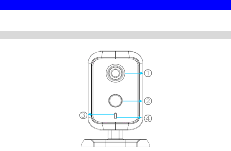
Front – Wireless Network Camera
Figure 2: Front Panel
1. Lens No physical adjustment is required or possible for the lens, but you
should ensure that the lens cover remain clean. The image quality is
degraded if the lens cover is dirty or smudged.
2. PIR Sensor The PIR sensor is designed for human body detection.
3. Privacy LED On - The Privacy function is enabled.
Off - The Privacy function is disabled.
4. Microphone The built-in microphone is useful for bi-direction voice
conversation.
5
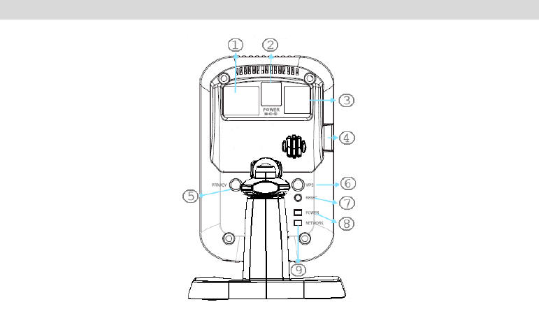
Rear – Wireless Network Camera
Figure 3: Rear Panel
1. LAN port Use a standard LAN cable to connect your Network Camera to a
10/100BaseT hub or switch.
Note:
Plugging in the LAN cable will disable the Wireless interface.
Only 1 interface can be active at any time.
The LAN cable should only be connected or disconnected when
the camera is powered OFF. Attaching or detaching the LAN
cable while the camera is powered on does NOT switch the
interface between wired and wireless.
2. Power Input Connect the supplied 12V power adapter here. Do not use other
power adapters; doing so may damage the camera.
3. External
Input/Output The GPIO terminal block includes 1 input port and 1 output port.
Please see the following External I/O Port section for more details.
4. Micro-SD Card
slot Insert the SD card into the slot, if required.
5. Privacy Button On (Green) - The privacy mode is activated. User can not access to
the video/audio from the camera.
Off - The privacy mode is not in use. User can get access to the
video/audio from the camera.
6. WPS Button Push the WPS button on the device and on your other wireless
device to perform WPS function that easily creates an encryption-
secured wireless connection automatically.
WPS PBC Mode. When pressed and released (less then 3
seconds), the Network Camera will be in the WPS PBC mode
(Auto link mode).
WPS Pin Code Mode. When pressed and held for over 3
seconds, the Network Camera will be in the WPS Pin Code
mode.
7. Reset Button This button is recessed; you need a pin or paper clip can be used to

6
depress it. It can be activated at any time the camera is in the
"ready" mode.
Reset to manufacturer default valued and reboot. When
pressed and held over 10 seconds, the settings of Network
Camera will be set to their default values.
Note:
After this procedure is completed, the Power LED will blink three
times to confirm that the reset was completed successfully.
8. Power LED
(Green) On - Power on.
Off - No power.
Blinking - The Power LED will blink during start up. This will take
55 to 57 seconds.
9. Network//WPS
LED
(Green, Amber)
On (Green) - Network (Wireless or LAN) connection is available.
Off - Wireless or LAN is not connected or camera is not
sending/receiving data.
Blinking (Green) - Data is being transmitted or received via the
LAN or Wireless connection.
On (Amber) - If the LED is on for 5 seconds, the WPS function is
failed.
Blinking (Amber) - WPS function is being processed.
External I/O Port
The following is the I/O port image and the definition table:
Pin Definition
Pin No Function Description
1 DI Photo Coupler Input:
Type: Photo coupler
Isolated digital input port which can be used to connect DI/GND.
Connect to DI/GND to activate or leave floating (or unconnected)
to deactivate.
2 GND DI/GND
3 DO Open Collector Output:
Type: NPN transistor
Collector (Pin3) to emitter input voltage (Pin4):+24VDC
Collector current: 100mA
This output has an open collector NPN transistor with the emitter
connected to GND (Pin4). If it is used with an external relay, a
diode must be connected in parallel with the load for protection

7
against any voltage transients.
4 GND DO/GND
Package Contents
The following items should be included: If any of these items are damaged or missing, please
contact your dealer immediately.
1. Wireless Network Camera
2. Camera Stand
3. Power adapter
4. Quick Installation Guide

8
Chapter 2
Basic Setup
This Chapter provides details of installing and configuring the Network
Camera.
System Requirements
To use the wired LAN interface, a standard 10/100BaseT hub or switch and network cable
is required.
To use the Wireless interface on the wireless model, other Wireless devices must be
compliant with the IEEE802.11b, IEEE802.11g or IEEE 802.11n specifications. All
Wireless stations must use compatible settings.
The default Wireless settings are:
Mode: Infrastructure
SSID: ANY
Wireless Security: Disabled
Domain: USA
Channel No.: Auto
Installation – Wireless Network Camera
1. Assemble the Camera
Attach the Camera Stand to the camera.
2. Connect the LAN Cable
Connect the Network Camera to a 10/100BaseT hub or switch, using a standard LAN
cable.
For this Model, it will disable the Wireless Interface. The
Wireless and LAN interfaces cannot be used simultaneously.
Using the LAN interface is recommended for initial
configuration. After the Wireless settings are correct, the
Wireless interface can be used.
The first time you connect to the camera, you should connect
the LAN cable and configure the Network Camera with
appropriate settings. Then you can unplug the LAN cable and
power off the camera. The Network Camera will be in wireless
interface when you power on the camera again.
2
9
3. Power Up
Connect the supplied 12Vpower adapter to the Network Camera and power up. Use only
the power adapter provided. Using a different one may cause hardware damage.
4. Check the LEDs
The Power LED will turn on briefly, then start blinking. It will blink during startup, which
takes 55 to 57 seconds. After startup is completed, the Power LED should remain ON.
The Network LED should be ON.
For more information, refer to Physical Details – Wireless Network Camera in Chapter 1.
10
Setup using the Windows Wizard
Initial setup should be performed using the supplied Windows-based setup Wizard. This
program can locate the Network Camera even if its IP address is invalid for your network. You
can then configure the Network Camera with appropriate TCP/IP settings for your LAN.
Subsequent administration can be performed with your Web browser, as explained in Chapter
5 - Web-based Management.
Setup Procedure
1. Insert the supplied CD-ROM into your drive. If the setup program does not start
automatically, run NetworkCamera.exe in the root folder.
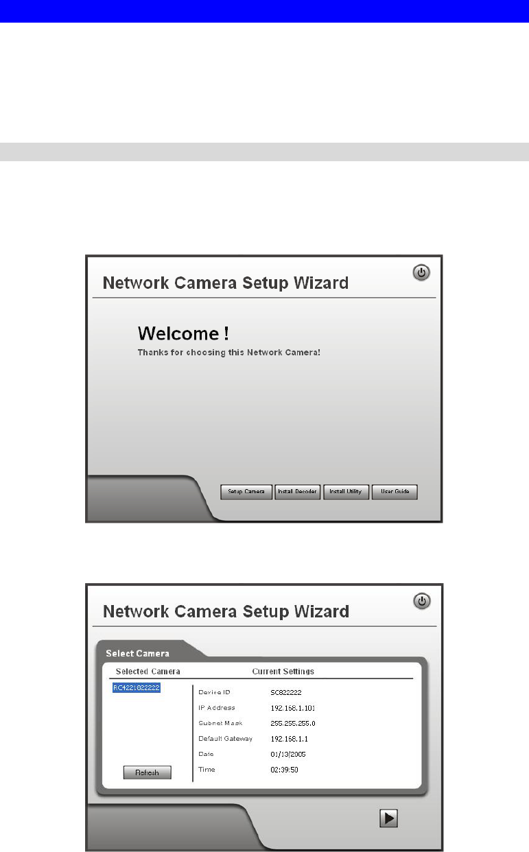
You will see the Welcome screen shown below.
Click the Setup Camera button to start the setup Wizard
Figure 4: Welcome Screen
2. The next screen, shown below, will list all the Network Cameras on your LAN.
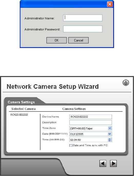
Figure 5: Camera List Screen
11
Select the desired Camera from the list on the left. The current settings for the selected
Camera will be displayed in the table on the right.
Click Next to continue.
3. You will be prompted to enter the Administrator Name and Administrator Password, as
shown below.
If using the default values, enter administrator for the name, and leave the
password blank.
Otherwise, enter the Administrator Name and Administrator Password set on the
Maintenance screen.
Figure 6: Password Dialog
4. This screen allows you to enter a suitable Description, and set the correct Time Zone,
Date, and Time. Make any desired changes, then click Next to continue.
Figure 7: Camera Settings
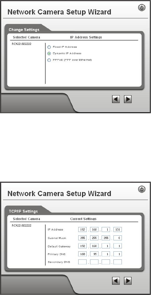
5. On the following IP Address Settings screen, shown below, choose Fixed IP Address,
Dynamic IP Address or PPPoE.
12
Figure 8: Fixed or Dynamic IP Selection
Fixed IP Address is recommended, and can always be used.
Dynamic IP Address can only be used if your LAN has a DCHP Server.
PPPoE (PPP over Ethernet) is the most common login method, widely used with
DSL modems.
Click Next to continue.
6. If you chose Fixed IP Address, the following TCP/IP Settings screen will be displayed.
Figure 9: TCP/IP Settings
Enter an unused IP Address from within the address range used on your LAN.
The Subnet Mask and Default Gateway fields must match the values used by PCs on
your LAN.
The Primary DNS address is required in order to use the E-mail alert or Dynamic
DNS features. Enter the DNS (Domain Name Server) address recommended by your
ISP.
The Secondary DNS is optional. If provided, it will be used if the Primary DNS is
unavailable.
13
Click Next to continue.
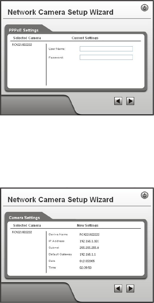
7. If you chose PPPoE, the following PPPoE Settings screen will be displayed.
Figure 10: PPPoE Settings Screen
Enter the User Name provided by your ISP.
Enter the Password for the user name above.
Click Next.
8. The next screen, shown below, displays all details of the Network Camera.
Click Next if the settings are correct
Click Back to modify any incorrect values.
Figure 11: Save Settings
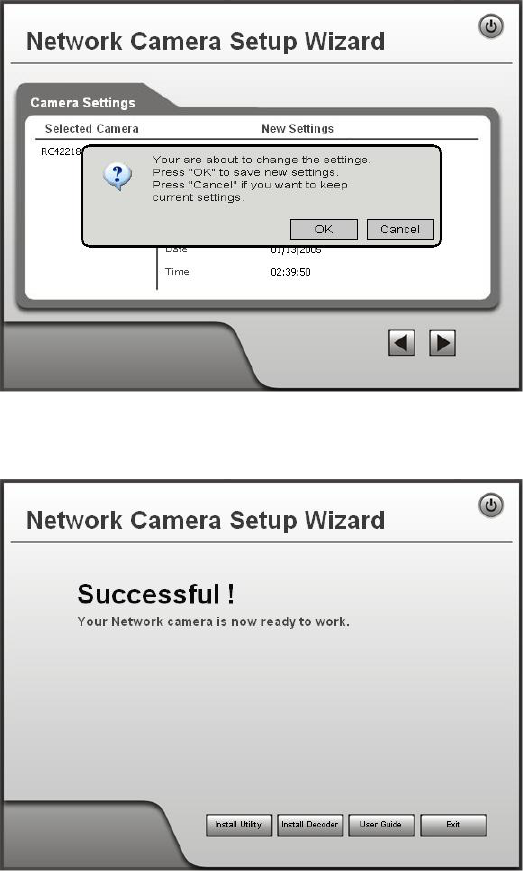
9. Click OK to confirm that you want to save the new settings. If you want to cancel your
changes, click Cancel.
14
Figure 12: Confirm Screen
10. After clicking OK, you will see the screen below.
Figure 13: Final Screen
Clicking the Install Utility button will install the Viewing/Recording utility described in
Chapter 6 - Windows Viewing/Recording Utility.
11. Click Exit to end the Wizard.
Setup is now complete.

15
Chapter 3
Viewing Live Video
This Chapter provides basic information about viewing live video.
Overview
After finishing setup via the Windows-based Wizard, all LAN users can view live video using
Internet Explorer on Windows.
This Chapter has details of viewing live video using Internet Explorer.
But many other powerful features and options are available:
To view multiple cameras simultaneously, or record video (either interactively or by
schedule), you should install the Windows Viewing/Recording utility. Refer to Chapter 6 -
Windows Viewing/Recording Utility for details on installing and using this program.
The camera administrator can also adjust the Video Stream, and restrict access to the video
stream to known users by requiring viewers to supply a username and password. See
Chapter 4 - Advanced Viewing Setup for details.
To make Live Video from the camera available via the Internet, your Internet Gateway or
Router must be configured correctly. See Making Video available from the Internet in
Chapter 4 - Advanced Viewing Setup for details.
Requirements
To view the live video stream generated by the Network Camera, you need to meet the
following requirements:
Windows XP, 32-bit Windows Vista/Windows 7.
Internet Explorer 6 or later, Firefox 3.0 or later.
Connecting to a Camera on your LAN
To establish a connection from your PC to the Network Camera:
1. Use the Windows utility to get the IP address of the Network Camera.
2. Start Internet Explorer.
3. In the Address box, enter "HTTP://" and the IP Address of the Network Camera.
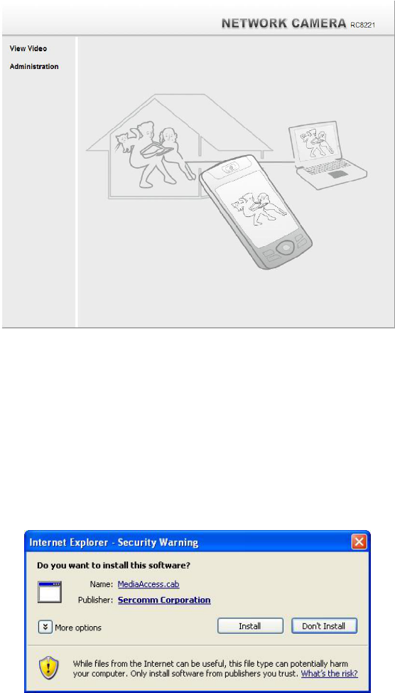
4. When you connect, the following screen will be displayed.
3

16
Figure 14: Home Screen
5. Click View Video.
6. If the Administrator has restricted access to known users, you will then be prompted for a
username and password.
Enter the name and password assigned to you by the Network Camera administrator.
7. The first time you connect to the camera, you will be prompted to install an ActiveX
component (OCX or CAB file), as in the example below.
You must install this ActiveX component (OCX or CAB file) in order to view the
Video stream in Internet Explorer.
Click the "Yes" button to install the ActiveX component.
Figure 15: ActiveX OCX Prompt
8. Video will start playing automatically. There may be a delay of a few seconds while the
video stream is buffered.

17
Connecting to a Camera via the Internet
You can NOT connect to a camera via the Internet unless the camera
Administrator has configured both the camera and the Internet Gateway/Router
used by the camera.
See Making Video available from the Internet in Chapter 4 - Advanced Viewing Setup for
details of the required configuration.
Also, you need a broadband Internet connection to view video effectively. Dial-up connections
are NOT supported.
To establish a connection from your PC to the Network Camera via the Internet:
1. Obtain the following information from the Administrator of the camera you wish to
connect to:
Internet IP Address or Domain Name of the camera.
Port number for HTTP connections.
Login (username, password) if required.
2. Start Internet Explorer.
3. In the Address box, enter the following:
HTTP://Internet_Address:port_number
Where Internet_Address is the Internet IP address or Domain Name of the camera,
and port_number is the port number used for HTTP (Web) connections to the camera.
Examples using an IP address:
HTTP://203.70.212.52:1024
Where the Internet IP address is 203.70.212.52 and the HTTP port number is 1024.
Example using a Domain Name:
HTTP://mycamera.dyndns.tv:1024
Where the Domain name (using DDNS in this example) is mycamera.dyndns.tv and
the HTTP port number is 1024.
18
4. When you connect, the following screen will be displayed.
Figure 16: Home Screen
5. Click View Video.
6. If the Administrator has restricted access to known users, you will then be prompted for a
username and password.
Enter the name and password assigned to you by the Network Camera administrator.
7. The first time you connect to the camera, you will be prompted to install an ActiveX
component (OCX or CAB file), as in the example below.
You must install this ActiveX component (OCX or CAB file) in order to view the
Video stream in Internet Explorer.
Click the "Yes" button to install the ActiveX component.
Figure 17: ActiveX OCX Prompt
8. Video will start playing automatically. There may be a delay of a few seconds while the
video stream is buffered.
19
Viewing Live Video
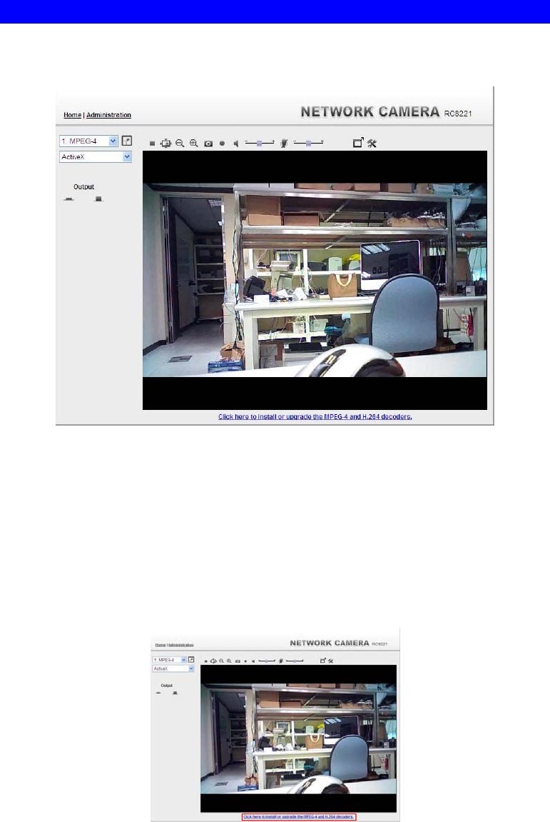
After installing the ActiveX component, you will be able to view the live video stream in its
own window, as shown below.
Figure 18: View Video Screen
There are a number of options available on this screen, accessed by select list, button or icon.
See the table below for details.
Note: The options can only be configured while using IE browser. Other browsers can just
view the video rather than configuration.
If after installing the OCX, the video still cannot be viewed, please install the decoders to solve
this problem. You can install it from the following screens:
Supplied Windows-based setup Wizard
View Video Screen (preferred)
Figure 19: Install Decoders
Motion Detection Screen
20
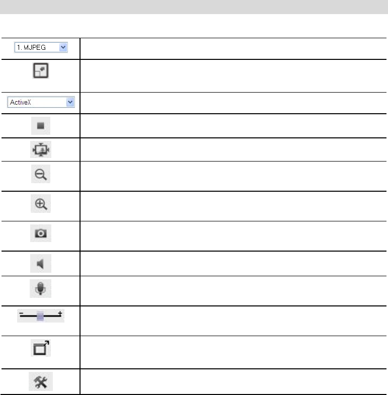
General Options
These options are always available, regardless of the type of camera you are connected to.
Streaming. Use this drop-down list to select the desired streaming.
Full Size. When using high-resolution mode (1280*720), click this
button to see the full size of the image.
Select the desired option from the drop-down list.
Use this icon to start/stop viewing.
Use this icon to make the image back to original size.
Zoom Out. A digital zoom out feature is available. To zoom out the
window, click this icon.
Zoom In. A digital zoom in feature is available. To zoom in the
window, click this icon.
Snapshot. Click this to take a single JPEG "snapshot" image of the
current video.
Speaker On/Off. Use this button to turn the PC's speaker on or off.
Microphone On/Off. Use this button to toggle the microphone on or
off.
Volume. If Speaker or Microphone is enabled, use this slider to adjust
the volume.
Full Screen Display. Click this button to see the full screen of the
image.
Setup. Select the desired folder to save the file.
21
Chapter 4
Advanced Viewing Setup
This Chapter provides information about the optional settings and features for
viewing video via the Network Camera. This Chapter is for the Camera
Administrator only.
Introduction
This chapter describes some additional settings and options for viewing live Video:
Adjusting the video image
Controlling user access to the live video stream
Making video available from the Internet
Using the Motion Detection feature
Adjusting the Video Image
If necessary, the Network Camera Administrator can adjust the Video image.
To Adjust the Video Image:
1. Connect to the Web-based interface of the Network Camera. (See Chapter 5 - Web-based
Management for details.)
2. Select Administration, then Streamings. You will see a screen like the example below.
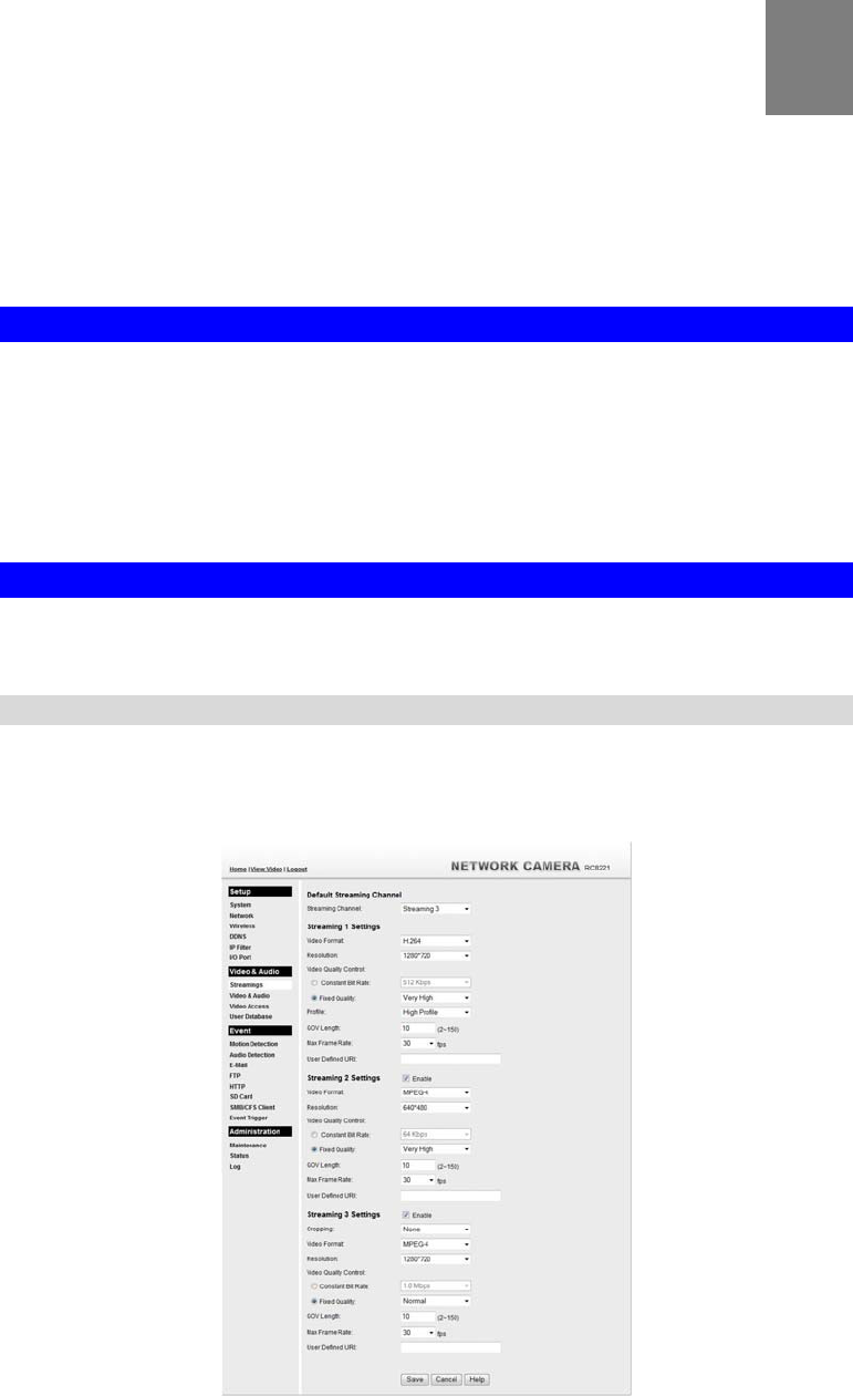
Figure 20: Streamings Screen
4

22
3. Make the required adjustments, as explained below, and save your changes.
Default Streaming
Channel Select the default channel for streaming from the drop-down list.
Streaming 1 Settings
Video Format Select the desired format from the list.
Resolution Select the desired video resolution format.
Video Quality
Control
Constant Bit Rate: Select the desired bit rate. The default is set
to 1.0 Mbps.
Fixed Quality: Select the desired option. The default fix quality
is set to Normal.
Profile This is only for H.264 format only. There are 3 options:
Baseline Profile
Main Profile
High Profile
Fixed Video
Quality This option is for MJPEG format only. Select the desired option.
The default fix quality is set to Normal.
GOV Length Adjust the GOV interval in frame base. "2" means 1 I frame and 1 P
Frame. "3" means 1 I frame and 2 P Frames. Enter the desired value
between 2 and 150.
Max. Frame Rate Select the desired Maximum frame rate for the video stream.
The default value is 30.
User Defined URI You may enter the URI up to 32 characters long for accessing the
live video from camera through cell phone connection.
Streaming 2/3 Settings
Enable Check the box if you want to enable the streaming.
Cropping
(Streaming 3 Only) Choose the desired option as required.
Video Format Select the desired format from the list.
Resolution Select the desired video resolution format.
Video Quality
Control
Constant Bit Rate: Select the desired bit rate. The default is set
to 1.0 Mbps.
Fixed Quality: Select the desired option. The default fix quality
is set to Normal.
Profile This is only for H.264 format only. There are 3 options:
Baseline Profile
Main Profile
High Profile
Fixed Video
Quality This option is for MJPEG format only. Select the desired option.
The default fix quality is set to Normal.
GOV Length Adjust the GOV interval in frame base. "2" means 1 I frame and 1 P
Frame. "3" means 1 I frame and 2 P Frames. Enter the desired value
between 2 and 150.

23
Max. Frame Rate Select the desired Maximum frame rate for the video stream.
The default value is 30.
User Defined URI You may enter the URI up to 32 characters long for accessing the
live video from camera through cell phone connection.
24
Controlling User Access to the Video Stream
By default, anyone can connect to the Wireless Network Camera and view live Video at any
time.
If desired, you can limit access to scheduled times, and also restrict access to known users.
To Control User Access to Live Video:
1. Connect to the Web-based interface of the Network Camera. (See Chapter 5 - Web-based
Management for details.)
2. Select Administration, then Video Access.
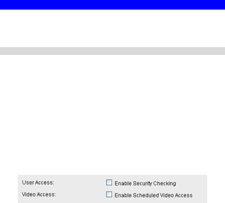
3. Set the desired options for Access.
Access
Select the desired option as required:
If the User Access is enabled, users will be prompted for a username and password when
they connect to the camera for viewing video.
When Video Access is enabled, viewing video is only available during the scheduled
periods, and unavailable at other times. If this option is selected, you need to define a
schedule; otherwise it is always disabled.
However, viewing video is still possible by logging in as the Administrator.
Figure 21: Controlling User Access
See Chapter 5 - Web-based Management for further details about using the Video Access and
User Database screens.
25
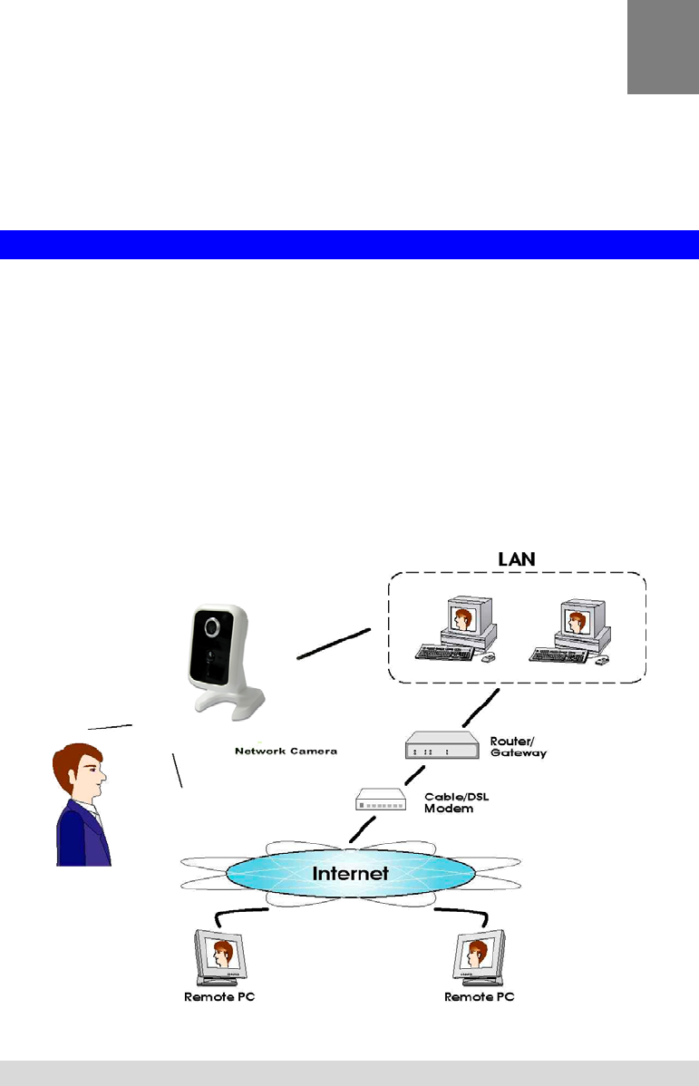
Making Video available from the Internet
If your LAN is connected to the Internet, typically by a Broadband Gateway/Router and
Broadband modem, you can make the Network Camera available via the Internet. You will
need to configure your Router or Gateway to allow connections from the Internet to the camera.
Router/Gateway Setup
Your Router or Gateway must be configured to pass incoming TCP (HTTP) connections (from
Internet Viewers) to the Network Camera. The Router/Gateway uses the Port Number to
determine which incoming connections are intended for the Network Camera.
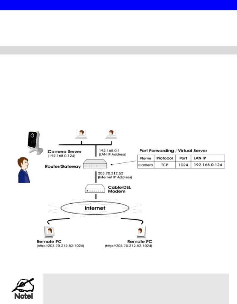
This feature is normally called Port Forwarding or Virtual Servers, and is illustrated below.
The Port Forwarding/Virtual Server entry tells the Router/Gateway that incoming TCP
connections on port 1024 should be passed to the Network Camera. If necessary, check the
user manual for your Router/Gateway for further details.
Figure 22: Connecting via the Internet
The "Port" for the Port Forwarding / Virtual Server entry
above is the " Secondary Port" number specified on the
Network screen of the Network Camera.
26
Network Camera Setup
The Wireless Network Camera configuration does NOT have be changed, unless:
You wish to change the port number from the default value.
You wish to use the DDNS (Dynamic DNS) feature of the Network Camera.
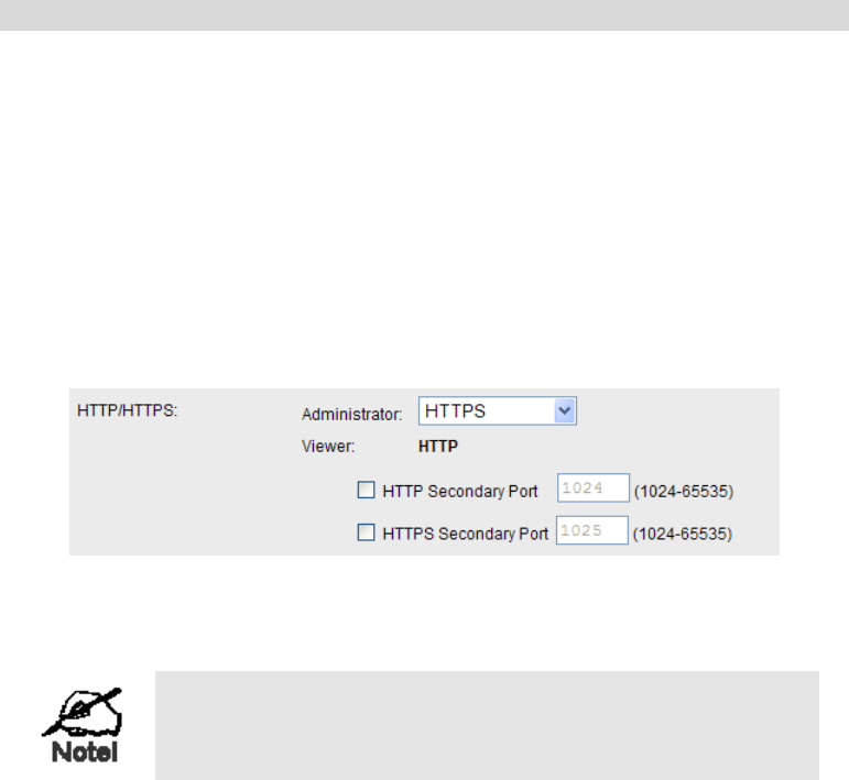
HTTPS Port Configuration
Normally, HTTP (Web) connections use port 80. Since the Network Camera uses HTTP, but
port 80 is likely to be used by a Web Server, you can use a different port for the Network
Camera. This port is called the Secondary Port.
The default HTTP/HTTPS Secondary Port is 1024/1025. If you prefer to use a different port
number, you can specify the port number on the Network Camera's Network screen, as shown
below.
Figure 23: Network Screen
See Chapter 5 - Web-based Management for further details on using the Network screen.
Viewers need to know this port number in order to connect
and view live Video, so you must inform viewers of the
correct port number.
DDNS (Dynamic DNS)
Many internet connections use a "Dynamic IP address", where the Internet IP address is
allocated whenever the Internet connection is established.
This means that other Internet users don't know the IP address, so can't establish a connection.
DDNS is designed to solve this problem, by allowing users to connect to your LAN using a
domain name, rather than an IP address.
To use DDNS:
1. Register for the DDNS service with a supported DDNS service provider. You can then
apply for, and be allocated, a Domain Name.
2. Enter and save the correct DDNS settings on the DDNS screen of the Network Camera.
3. Both Router and Camera should use the same port number for DDNS service.
27
Figure 24: DDNS Screen
4. Operation is then automatic:
The Network Camera will automatically contact the DDNS server whenever it detects
that the Internet IP address has changed, and inform the DDNS server of the new IP
address.
Internet users can then connect to the camera using the Domain Name allocated by the
DDNS service provider.
Example: HTTP://mycamera.dyndns.tv:1024
mycamera.dyndns.tv is domain host name. 1024 is the port number.
28
Viewing Live Video via the Internet
Clients (viewers) will also need a broadband connection; dial-up connections are NOT
recommended.
Viewing Live Video Using your Web Browser
If using your Web browser, you need to know the Internet IP address (or the Domain name) of
the camera's Router/Gateway, and the correct port number.
Enter the Internet address of the Router/Gateway, and its port number, in the Address (or
Location) field of your Browser.
Example - IP address:
HTTP://203.70.212.52:1024
Where the Router/Gateway's Internet IP address is 203.70.212.52 and the "Secondary
Port" number on the Network Camera is 1024.
Example - Domain Name:
HTTP://mycamera.dyndns.tv:1024
Where the Router/Gateway's Domain name is mycamera.dyndns.tv and the "Secondary
Port" number on the Network Camera is 1024.
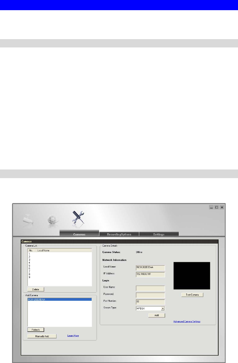
Viewing Live Video with the Viewing/Recording Utility
If using the Windows Viewing/Recording Utility, the details of the Network Camera must be
entered on the Setup screen.
Figure 25: Add Camera from LAN
See Chapter 6 - Window Viewing/Recording Utility for full details on using the Windows
Viewing/Recording utility.
29
Motion Detection Alerts
The Motion Detection feature can generate an Alert when motion is detected.
The Network Camera will compare consecutive frames to detect changes caused by the
movement of large objects.
But the motion detector can also be triggered by:
Sudden changes in the level of available light
Movement of the camera itself.
Try to avoid these situations. The motion detection feature works best in locations where there
is good steady illumination, and the camera is mounted securely. It cannot be used outdoors
due to the sensitivity of the CMOS sensor.
Note: The Motion Detection settings can only be configured while using IE browser.
To Use Motion Detection Alerts
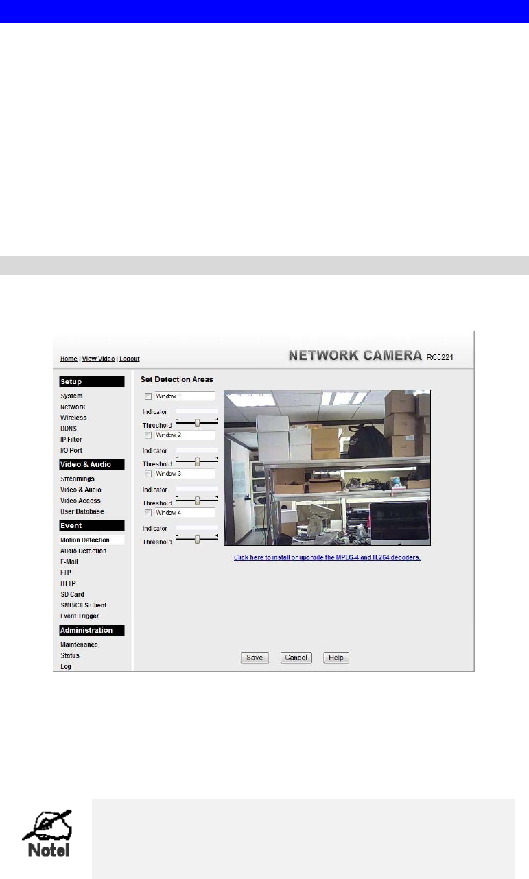
Using the Web-based interface on the Network Camera, select the Motion Detection screen,
then configure this screen as described below.
Figure 26: Motion Detection
1. Enable the Motion Detection feature.
2. Set the area or areas of the video image to be examined for movement. You can define up
to 4 areas, and set the motion threshold individually for each area.
3. If using a schedule, define the desired schedule in Event Trigger screen.
4. Save your changes.
If the Motion Detection feature is enabled, but the related
options in the Event Trigger screen are not enabled, then the
only action when motion is detected is to log this event in the
system log.

30
Chapter 5
Web-based Management
This Chapter provides Setup details of the Network Camera’s Web-based
Interface. This Chapter is for the Camera Administrator only.
Introduction
The Wireless Network Camera can be configured using your Web Browser. The Network
Camera must have an IP address which is compatible with your PC.
The recommended method to ensure this is to use the supplied Windows-based Wizard, as
described in Chapter 2 - Basic Setup.
Connecting to Network Camera
If using only your Web Browser, use the following procedure to establish a connection
from your PC to the Network Camera:
Once connected, you can add the Network Camera to your Browser's Favorites or
Bookmarks.
Connecting using your Web Browser
1. Use the Windows utility to get the IP address of the Network Camera.
2. Start your WEB browser.
3. In the Address box, enter "HTTP://" and the IP Address of the Network Camera.
4. You will then be prompted for a username and password.
If using the default values, enter administrator for the name, and leave the
password blank.
Otherwise, enter the Administrator ID and Administrator Password set on the
Maintenance screen.
5
31
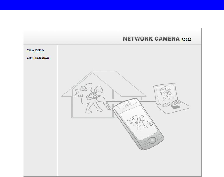
Welcome Screen
When you connect, the following screen will be displayed.
Figure 27: Welcome Screen
The menu options available from this screen are:
View Video - View live Video using your Web Browser. See Chapter 3 - Viewing Live
Video for details.
Administration - Access the Administration menu.

32
Administration Menu
Clicking on Administration on the menu provides access to all the settings for the Network
Camera.
The Administration menu contains the following options:
Setup
System
Network
Wireless
DDNS
IP Filter
I/O Port
Video & Audio
Streaming
Video & Audio
Video Access
User Database
Event
Motion Detection
Audio Detection
E-Mail
FTP
HTTP
SD Card
SMB/CIFS Client
Event Trigger
Administration
Maintenance
Status
Log
33
System Screen
After clicking Administration on the main menu, or selecting System on the Administration
menu, you will see a screen like the example below.
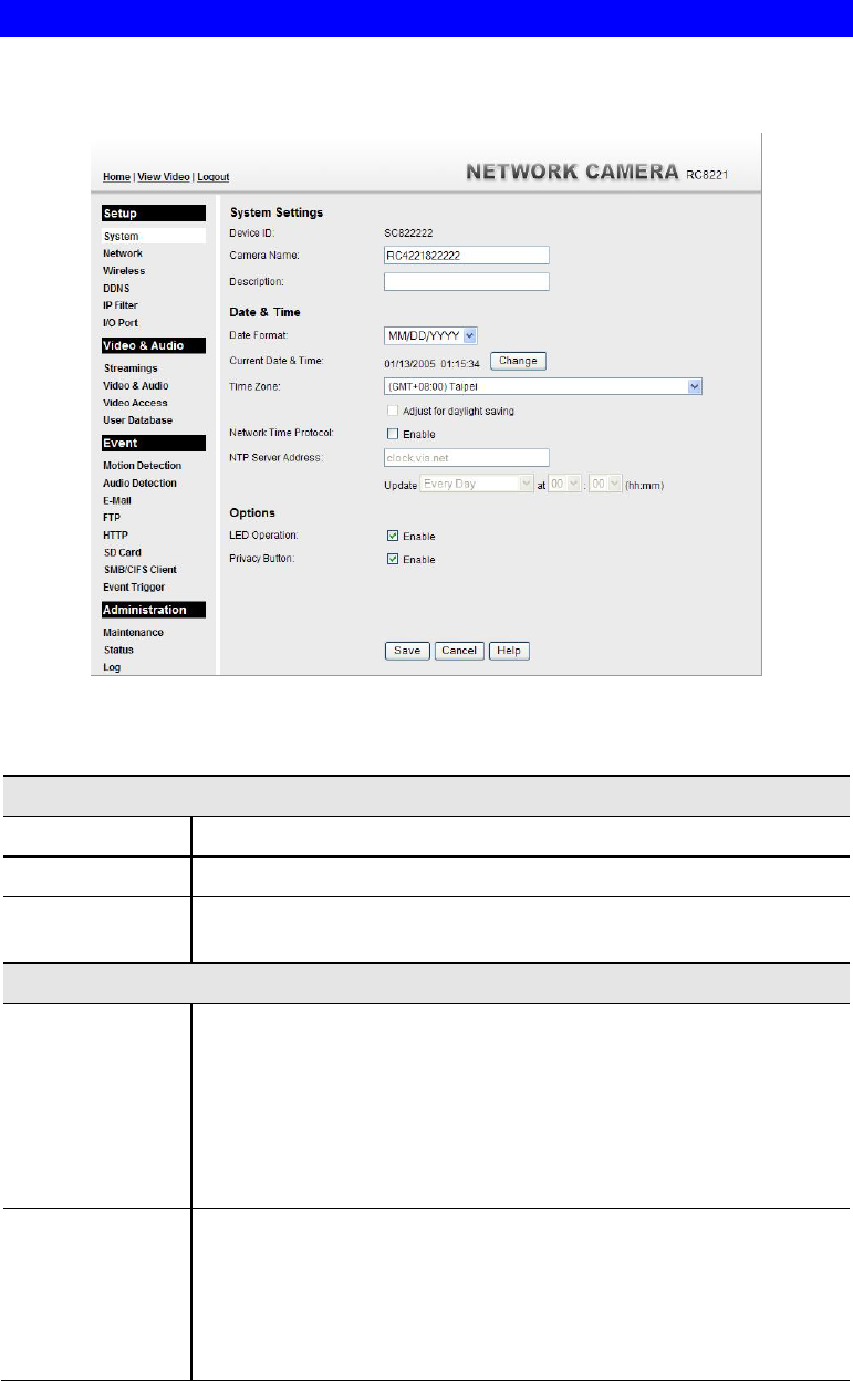
Figure 28: System Screen
Data - System Screen
System Settings
Device ID This displays the ID for the Network Camera.
Camera Name Enter the desired name for the Network Camera.
Description This field is used for entering a description, such as the location of the
Network Camera.
Date & Time
Date Format Select the desired date format, it will also be used to display the date
and time as an overlay on the video image.
The abbreviations used to predefine the date formats are list as follows:
YYYY-MM-DD = Year-Month-Day, e.g. 2006-01-31
MM/DD/YYYY = Month/Day/Year, e.g. 01/31/2006
DD/MM/YYYY = Day/Month/Year, e.g. 31/01/2006
Current
Date & Time This displays the current date and time on the camera.
If it's not correct, click the Change button to modify the date/time
settings. This button will open a sub-screen where you have 2 options:
Set the camera's date and time to match your PC.
Enter the correct date and time.

34
Time Zone Choose the Time Zone for your location from the drop-down list.
If your location is currently using Daylight Saving, please enable the
Adjust for daylight saving checkbox.
Network Time
Protocol Enable or disable the Time Server feature as required.
If Enabled, the Network Camera will contact a Network Time Server at
regular intervals and update its internal timer.
NTP Server
Address Enter the address for the desired NTP server.
Update The Schedule determines how often the Network Camera contacts the
NTP Server.
Select the desired options.
LED Operation Enable this if you want to use this function.
Privacy Button If Enabled, click the Privacy button will stop uploading the stream
without turning the camera off. Click the button one more time to
continue uploading. The default is Enabled.
35
Network Screen
This screen is displayed when the Network option is clicked.
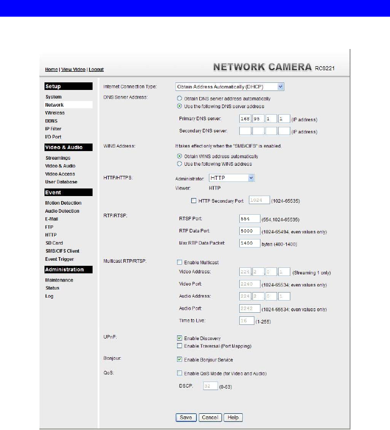
Figure 29: Network Screen

36
Data - Network Screen
Network
Internet Connection
Type There are 3 connection types:
Obtain Address Automatically (DHCP): If selected, the
Network Camera will obtain its IP address and related
information from a DHCP Server. Only select this option if
your LAN has a DHCP Server.
Static IP Address: If selected, you must assign the following
data to the Network Camera.
IP Address - Enter an unused IP address from the address
range used on your LAN.
Subnet Mask - Use the same value as PCs on your LAN.
Default Gateway - Use the same value as PCs on your
LAN.
PPPoE (PPP over Ethernet): This is the most common login
method, widely used with DSL modems. Normally, your ISP
will have provided some software to connect and login. This
software is no longer required, and should not be used.
Username - The user name (or account name) provided by
your ISP.
Password - Enter the password for the login name above.
Obtain DNS server
address
automatically
If selected, the Network Camera will use the DNS address or
addresses provided by the DHPC server.
This option is only available if the IP address setting is Obtain an
IP address Automatically.
Use the following
DNS server address Primary DNS server - Use the same value as PCs on your LAN.
Normally, your ISP will provide this address.
Secondary DNS server - This is optional. If entered, this DNS will
be used if the Primary DNS does not respond.
WINS Address There are 2 options:
Obtain WINS address automatically - If selected, the
Network Camera will obtain its IP address from DHCP server.
Use the following WINS address - Enter the IP address of
your WINS server.

37
HTTP/HTTPS This sets the port number for HTTP/HTTPS connections to the
Camera, whether for administration or viewing video.
The HTTP (HyperText Transfer Protocol) is used for the standard
of transferring files (text, graphic images and other multimedia
files) on the World Wide Web. The default HTTP port is 1024.
HTTPS (Hypertext Transfer Protocol Secure) can provide more
secure communication with the SSL/TLS protocol, which support
data encryption to HTTP clients and servers. The default HTTPS
port is 1025.
The Secondary port can be used for DDNS, other service and when
more than 2 cameras are in use.
If enabled, you can connect using either port 80 or the Secondary
port. You must enter the Secondary port number (between 1024 to
65535) in the field provided.
Note that when using a port number which is not 80, you must
specify the port number in the URL. For example, if the Camera's
IP address was 192.168.1.100 and the Secondary port was 1024,
you would specify the URL for the Camera as follows:
http://192.168.1.100:1024
RTP/RTSP The RTSP (Real Time Streaming Protocol), a standard for
connected client(s) to control streaming data (MPEG-4) over the
World Wide Web. Enter the RTSP Port number (between 1024 and
65535) in the field provided. The default RTSP Port is 554.
The RTP (Real Time Transport Protocol), an Internet protocol for
transmitting real-time data such as audio and video.
Max RTP Data Packet field will let users limit the size of the file.
Enter the desired value between 400 and 1400.
Note: RTSP and RTP settings are for cell phone only.
Multicast RTP/RTSP
Enable Multicast Enable the feature as required.
Video Address Enter the address of video (Streaming 1 only).
Video Port Enter the desired value (between 1024 to 65534) in the field
provided. The number you entered must be even values.
Audio Address Enter the address of the audio.
Audio Port Enter the desired value (between 1024 to 65534) in the field
provided. The number you entered must be even values.
Time to Live Enter the desired length of time, if the packets fail to be delivered
to their destination within. The Time to Live you entered must be
in-between 1 to 255.
UPnP
Enable Discovery If enabled, the Network Camera will broadcast its availability
through UPnP. UPnP compatible systems such as Windows XP will
then be able to detect the presence of the Network Camera.

38
Enable Traversal If enabled, HTTP connections (from your Web Browser or the
Viewer and Recorder utility) can use secondary port instead of port
80 (the standard HTTP port) to access the camera.
Bonjour
Enable Bonjour
Service If enabled, the Network Camera can be accessed through a
"Bonjour" enabled browser, such as Microsoft Internet Explorer
(with a Bonjour plug-in) or Safari browser. You can also find other
Bonjour-enabled devices on your network.
QoS
Enable QoS Mode If enabled, the throughput level (for Video and Audio) is
guaranteed through QoS (Quality of Service).
DSCP Enter the desired value of Differentiated Services Code Point
(DSCP). The value must be between 0 and 63.
39
Wireless Screen
This screen is displayed when the Wireless menu option is clicked.
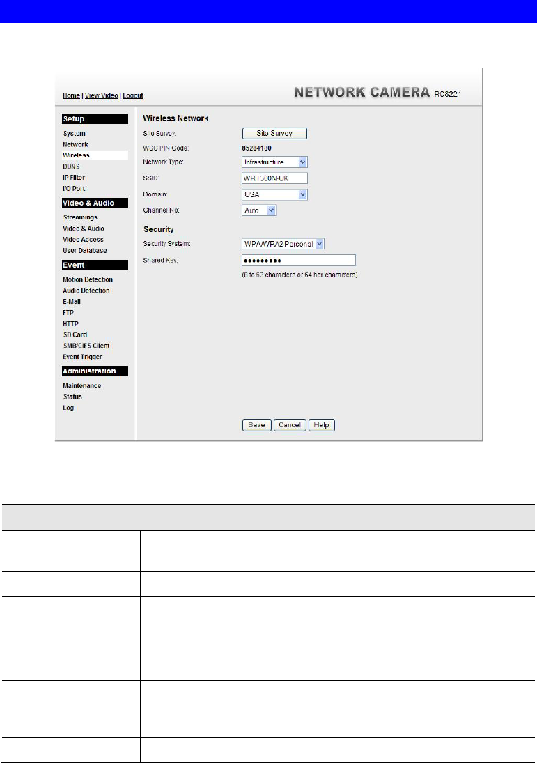
Figure 30: Wireless Screen
Data - Wireless Screen
Wireless Network
Site Survey Click the "Site Survey" button and select from a list of available
APs.
WSC PIN Code It displays the WSC PIN code number for the camera.
Network Type This determines the type of wireless communication used by the
Network Camera.
If you have an Access Point, select Infrastructure.
Otherwise, select Ad-hoc.
SSID This must match the value used by other devices on your wireless
LAN. The Default is ANY.
Note! The SSID is case sensitive.
Domain Select your region from the drop-down list.

40
Channel No. In Infrastructure mode, this setting is ignored. The Network
Camera will use the Channel set on the Access Point.
For Ad-hoc mode, select the Channel you wish to use on your
Network Camera. Other Wireless stations should use the same
setting.
If you experience interference (shown by lost connections
and/or slow data transfers) you may need to experiment with
different channels to see which one is the best.
Security
Security System Select the desired option, and then enter the settings for the selected
method:
Disabled - No security is used. Anyone using the correct SSID
can connect to your network. This is default.
WEP - The 802.11b standard. Data is encrypted before
transmission, but the encryption system is not very strong.
WPA/WPA2 Personal - Like WEP, data is encrypted before
transmission. WPA is more secure than WEP, and should be
used if possible. WPA Personal is the version of WPA which
does NOT require a Radius Server on your LAN.
WEP
Authentication Type Normally this can be left at the default value of "Automatic." If that
fails, select the appropriate value - "Open System" or "Shared
Key." Check your wireless card's documentation to see what
method to use.
Note: In Infrastructure mode, either setting will normally work,
since most Access Points can use both methods.
WEP Encryption Select the WEP Encryption level:
64 Bit Keys (10 Hex chars)
128 Bit Keys (26 Hex chars)
64 Bit Keys (5 ASCII chars)
128 Bit Keys (13 ASCII chars)
Passphrase Enter a word or group of printable characters in the Passphrase box
and click the "Generate Key" button to automatically configure the
WEP Key(s). If encryption strength is set to 64-bit, then each of the
four key fields will be populated with key values. If encryption
strength is set to 128-bit, then only the selected WEP key field will
be given a key value.
WEP Keys Use the radio buttons to select the default key.
Enter the key value you wish to use. Other stations must have
the same key values.
Keys must be entered in Hex. Hex characters are the digits (0 ~
9) and the letters A ~ F.
Click Clear Keys to set the Keys to be blank.

41
WPA/WPA2 Personal
Shared Key Enter the key value. Data is encrypted using a key derived from the
network key. Other Wireless Stations must use the same network
key. The PSK must be from 8 to 63 characters or 64 hex characters
in length.

42
DDNS Screen
Many Internet connections use a "Dynamic IP address", where the Internet IP address is
allocated whenever the Internet connection is established.
This means that other Internet users don't know the IP address, so can't establish a connection.
DDNS is designed to solve this problem, as follows:
You must register for the DDNS service with a DDNS service provider. The DDNS
Service provider will allocate a Domain Name to you upon request.
The DDNS settings on the DDNS screen above must be correct.
The Network Camera will then contact the DDNS server whenever it detects that the
Internet IP address has changed, and inform the DDNS server of the new IP address. (The
Check WAN IP Address determines how often the Network Camera checks if the Internet
IP address has changed.)
This system allows other internet users to connect to you using the Domain Name allocated by
the DDNS service provider.
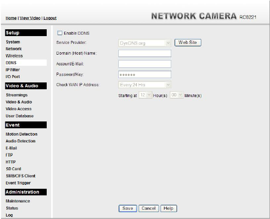
This screen is displayed when the DDNS menu option is clicked.
Figure 31: DDNS Screen
Data - DDNS Screen
DDNS
Enable DDNS Enable or disable the DDNS function, as required.
Only enable this feature if you have registered for the DDNS
Service with a DDNS Server provider.
Service Provider Choose a service provider from the list.
Web Site Button Click this button to open a new window and connect to the Web
site for the selected DDNS service provider.

43
Domain (Host)
Name Enter the Domain Name (Host Name) allocated to you by the
DDNS Server provider.
Account/E-Mail Enter the login name for the DDNS account.
Password/Key Enter the password for the DDNS account.
Check WAN IP
Address Set the schedule for checking if the Internet IP address has
changed. If the IP address has changed, the DDNS Server will be
notified.
NOTE: If the DDNS Service provided some software to perform
this IP address update or notification, you should NOT use this
software. The update is performed by the camera.
44
IP Filter
The IP Filter feature allows administrator to control network camera access by filtering IP
addresses. This screen is displayed when the IP Filter menu option is clicked.
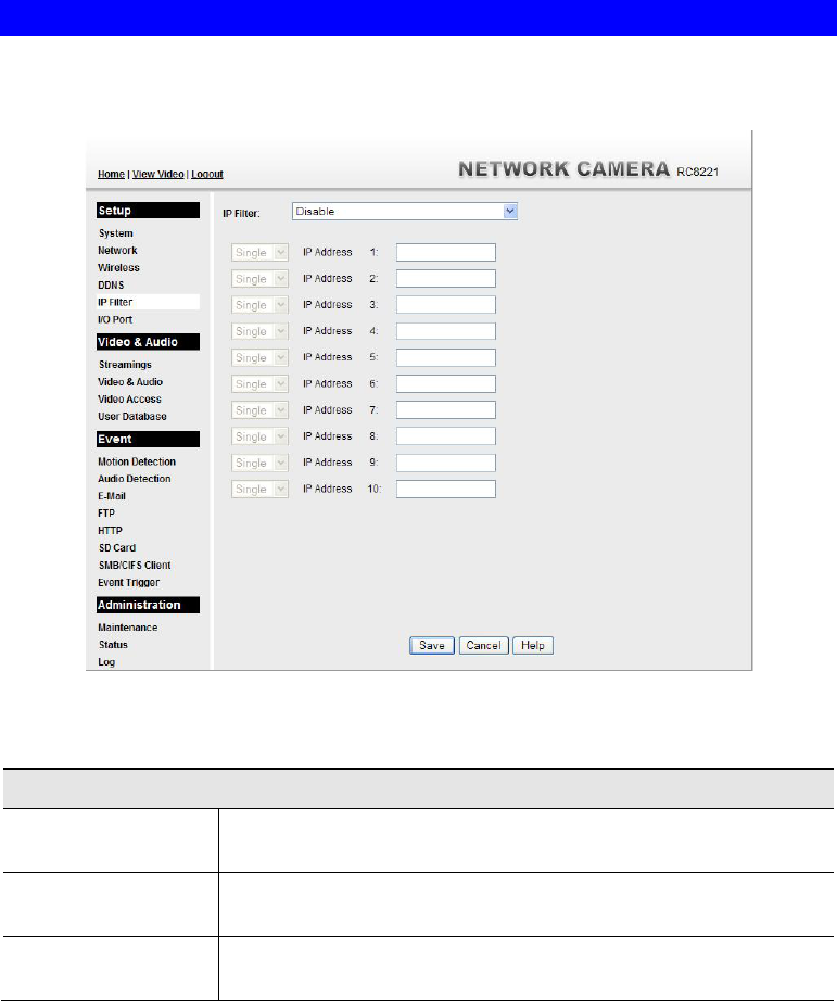
Figure 32: IP Filter Screen
Data - IP Filter Screen
IP Filter
IP Filter Select the desired method to perform the IP address (or addresses)
filtering function.
Single/Range Select to perform either single IP address or a range of IP addresses
that you desired.
IP Address Enter an IP address or a range of IP addresses you would like to
allow or deny.
45
I/O Port
The Network Camera supports 1 input port and 1 output port. This screen is displayed when
the I/O Port menu option is clicked.
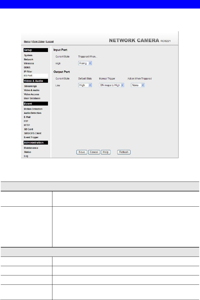
Figure 33: I/O Port Screen
Data - I/O Port Screen
Input Ports
Current State It indicates the current state of the input port. Once the configured
state is happened, it will trigger the event actions.
Triggered When… Select the desired State:
High
Low
Rising
Falling
Output Ports
Current State It indicates the current state of the output port.
Default State Select the desired option from the drop-down list.
Manual Trigger Select the option to control the output state.
Action When
Triggered If an event is happened, it will trigger the event alerting.
46
Streamings
This screen is displayed when the Streamings menu option is clicked.
If you want to view streaming via the cell phone:
1. Cell phone should be supported by 3GPP protocol.
2. Enter 554 for RTSP port number in the Network screen.
3. Both MPEG-4 and H.264 format support cell phone option.
4. Enter the following address in the URI:
RTSP:// Router IP address / User Defined URI
5. Select 15 fps for Max Frame Rate.
Note! Due to the bandwidth limitation for the cell phone usage, please set the resolution,
quality and frame rate to lower values.
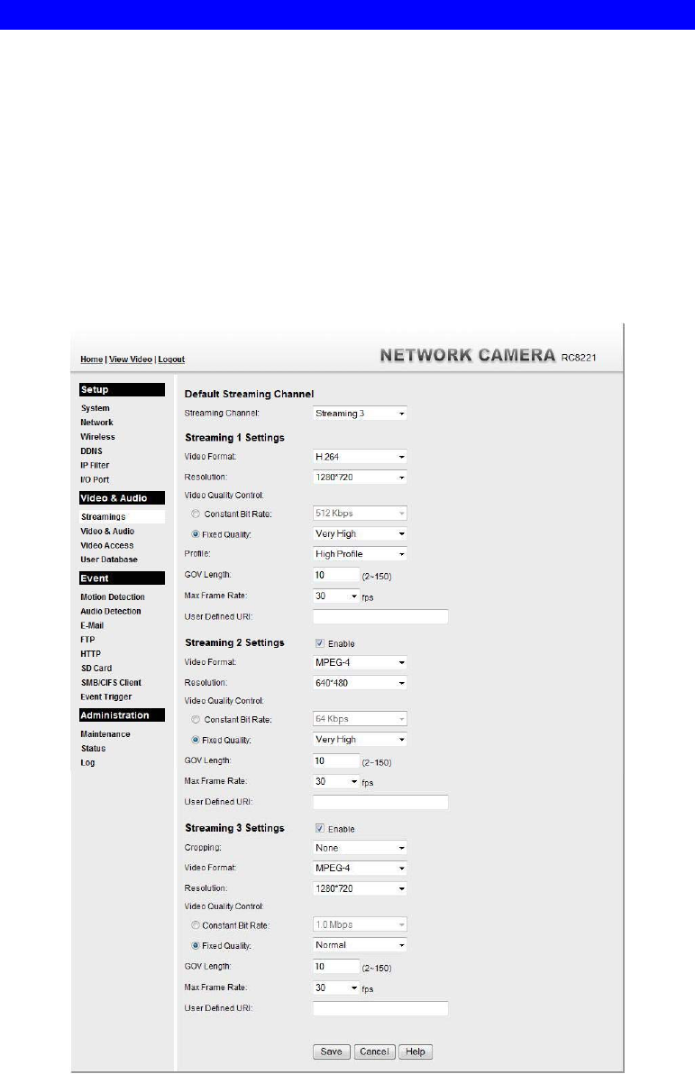
Figure 34: Streamings Screen

47
Data - Streamings Screen
Default Streaming
Channel Select the default channel for streaming from the drop-down list.
Streaming 1 Settings
Video Format Select the desired format from the list.
Resolution Select the desired video resolution format.
Video Quality
Control
Constant Bit Rate: Select the desired bit rate. The default is set
to 1.0 Mbps.
Fixed Quality: Select the desired option. The default fix quality
is set to Normal.
Profile This is only for H.264 format only. There are 3 options:
Baseline Profile
Main Profile
High Profile
Fixed Video
Quality This option is for MJPEG format only. Select the desired option.
The default fix quality is set to Normal.
GOV Length Adjust the GOV interval in frame base. "2" means 1 I frame and 1 P
Frame. "3" means 1 I frame and 2 P Frames. Enter the desired value
between 2 and 150.
Max. Frame Rate Select the desired Maximum frame rate for the video stream.
The default value is 30.
User Defined URI You may enter the URI up to 32 characters long for accessing the
live video from camera through cell phone connection.
Streaming 2/3 Settings
Enable Check the box if you want to enable the streaming.
Cropping
(Streaming 3 Only) Choose the desired option as required.
Video Format Select the desired format from the list.
Resolution Select the desired video resolution format.
Video Quality
Control
Constant Bit Rate: Select the desired bit rate. The default is set
to 1.0 Mbps.
Fixed Quality: Select the desired option. The default fix quality
is set to Normal.
Profile This is only for H.264 format only. There are 3 options:
Baseline Profile
Main Profile
High Profile
Fixed Video
Quality This option is for MJPEG format only. Select the desired option.
The default fix quality is set to Normal.
GOV Length Adjust the GOV interval in frame base. "2" means 1 I frame and 1 P
Frame. "3" means 1 I frame and 2 P Frames. Enter the desired value
between 2 and 150.

48
Max. Frame Rate Select the desired Maximum frame rate for the video stream.
The default value is 30.
User Defined URI You may enter the URI up to 32 characters long for accessing the
live video from camera through cell phone connection.
49
Video & Audio Screen
This screen is displayed when the Video & Audio menu option is clicked.
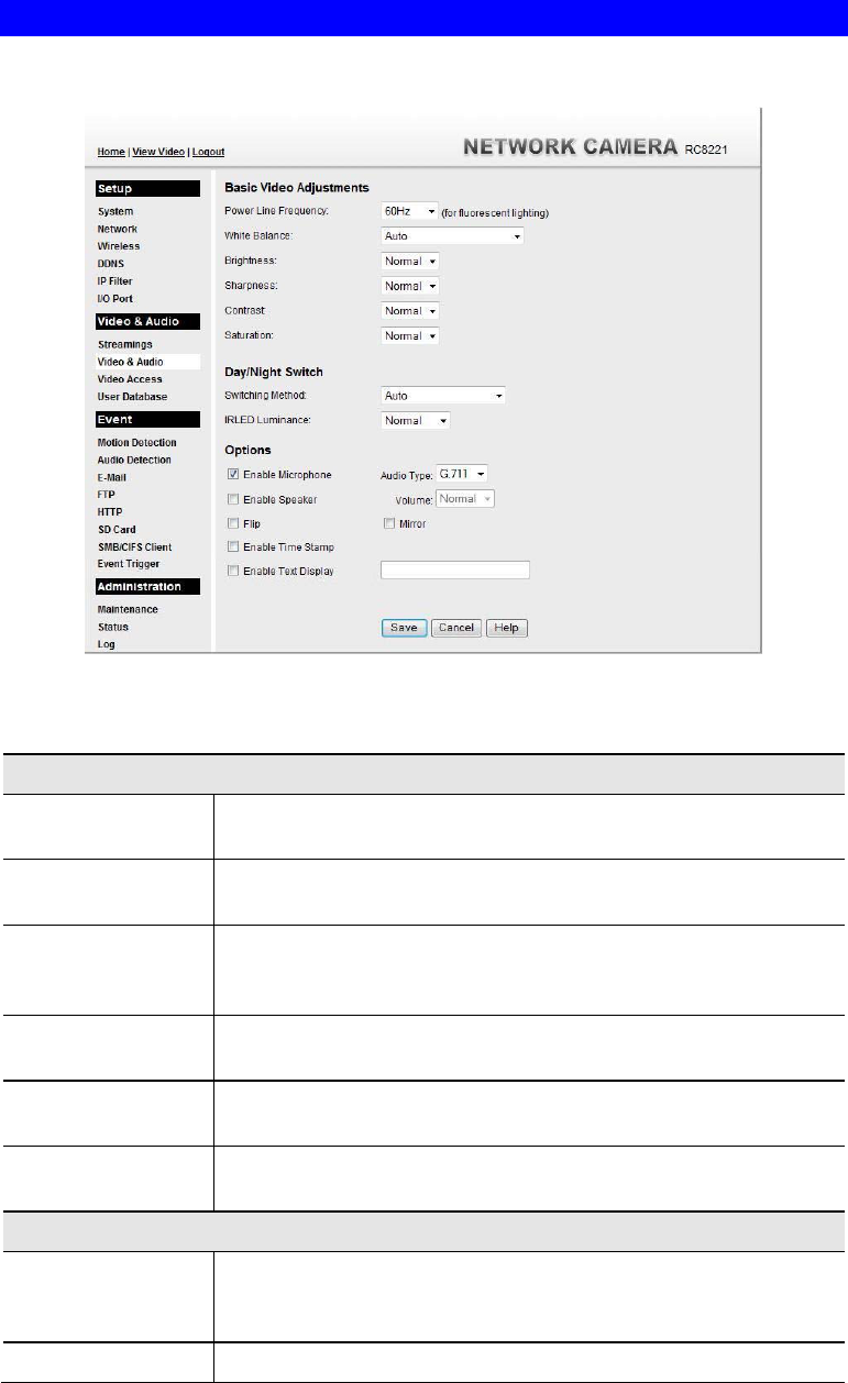
Figure 35: Video & Audio Screen
Data - Video & Audio Screen
Basic Video Adjustment
Power Line
Frequency Select the power line frequency (50Hz or 60Hz) used in your region,
to improve the picture quality under florescent lighting.
White Balance Select the desired option to match the current environment and
lighting.
Brightness If necessary, you can adjust the brightness to obtain a better image.
For example, if the camera is facing a bright light, the image may be
too dark. In this case, you can increase the brightness.
Sharpness Select the desired option for the sharpness. You can select a
Sharpness value between -3 and 3.
Contrast Select the desired option for the Contrast. You can select a value
between -3 and 3.
Saturation Select the desired option for the Saturation. You can select a value
between -3 and 3.
Day/Night Switch
Switching Method The Network Camera supports Day/Night mode switch for getting
better quality of the low light condition. Select the desired method to
use this function.
IRLED Luminance Select the desired lightness for the IR LED.

50
Options
Enable Microphone Enable audio by checking this checkbox. Using Audio will increase
the bandwidth requirements slightly.
Audio Type Select the desired audio type.
Enable Speaker Enable speaker sound by checking this checkbox.
Volume Choose the desired volume for the speaker.
Flip This setting will have the image swapped top-to-bottom.
Mirror This setting will have the image swapped left-to-right.
Enable Time Stamp If enabled, the current time will be displayed on the Video image.
Enable Text
Display Enable this setting if you want text to be displayed on the Video
image, and enter the desired text - up to 20 characters. This feature
is often used to identify each camera when multiple cameras are
installed.
51
Video Access Screen
This screen is displayed when the Video Access option is clicked.
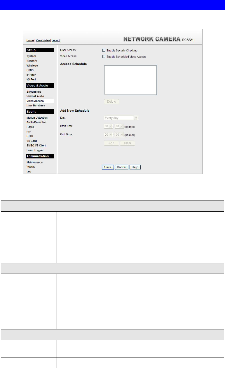
Figure 36: Video Access Screen
Data - Video Access Screen
User Access
Enable Security
Checking
If disabled (default) - No login required. Users do not have to
provide a username and password when they connect to the
camera for viewing video.
If enabled - Require login. Users will be prompted for a
username and password when they connect to the camera for
viewing video. The camera administrator must use the "User
Database" menu option to create the desired users.
Video Access
Enable Scheduled
Video Access
If enabled - Viewing video is available during the scheduled
periods, and unavailable at other times. If this option is selected,
you need to define a schedule. If no schedule is defined, this
option is always disabled.
If disabled - The option will remain disabled until you enable it.
Note that regardless of which setting is chosen, the Administrator
can ALWAYS access the camera and view live video.
Access Schedule
Scheduled Periods This displays all periods you have entered into the database. If you
have not entered any periods, this list will be empty.
Delete Use the Delete button to delete the selected item in the list.

52
Add New Schedule
Day Choose the desired option for the period.
Start Time Enter the start time using a 24 hr clock.
End Time Enter the end time using a 24 hr clock.
Add Click this button to add a new period.
Clear Use this button to clear the input fields.
53
User Database Screen
This screen is displayed when the User Database option is clicked.
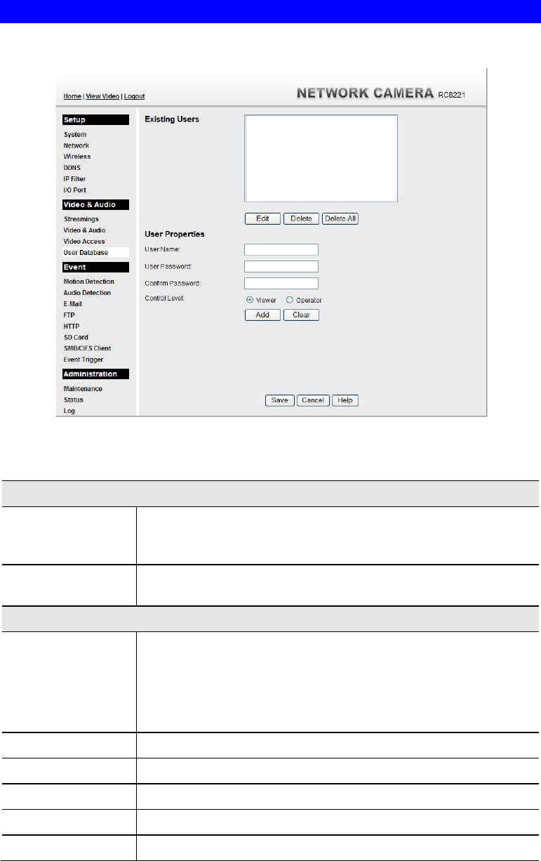
Figure 37: User Database Screen
Data - User Database Screen
Existing Users
User List This displays all users you have entered into the User database. If
you have not entered any users, this list will be empty.
The maximum number of users is 20.
Edit, Delete, Delete
All Use these buttons to manage the user database.
User Properties
User Name Enter the name for the user here.
Spaces, punctuation, and special characters must NOT be used
in the name.
The name is case insensitive (case is ignored), so you can not
have 2 names which differ only by case.
User Password The password for this user.
Confirm Password Re-enter the password for the user, to ensure it is correct.
Control Level Select either Viewer or Operator for the user you plan to add.
Add Button Click this button to add a new user, using the data shown on screen.
Clear Button Use this button to clear the input fields, ready to add a new user.
54
Motion Detection Screen
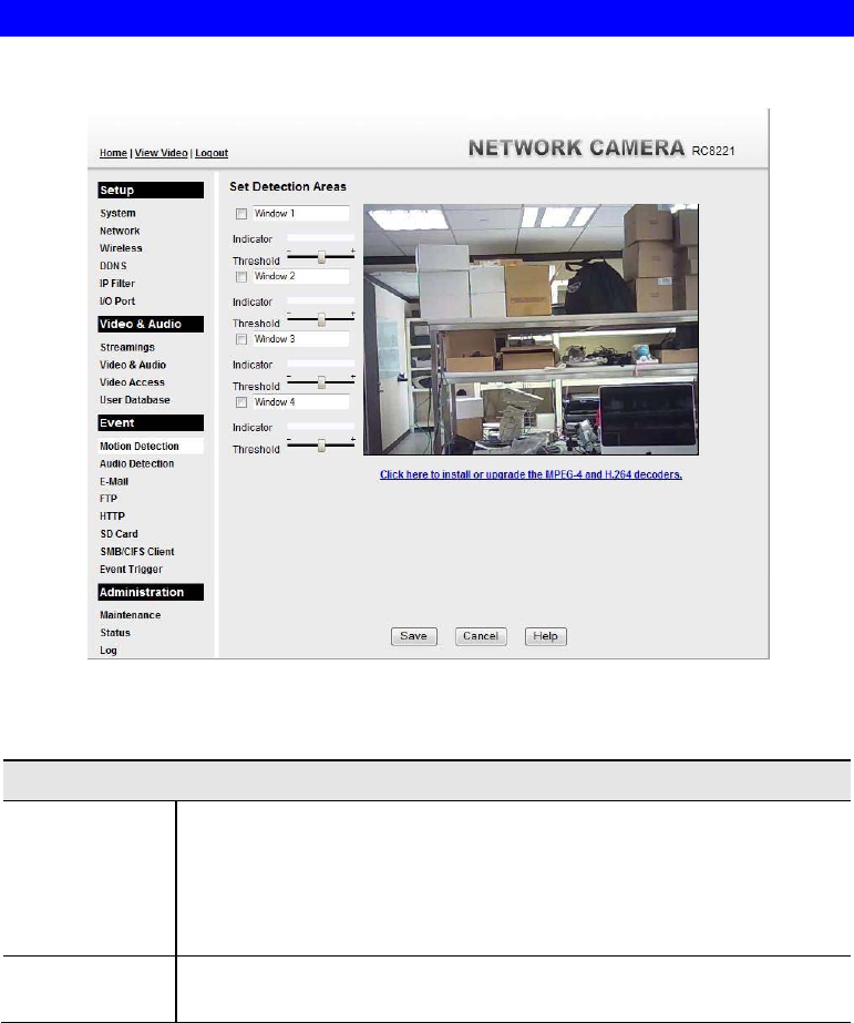
This screen is displayed when the Motion Detection option on the Event menu is clicked.
Figure 38: Motion Detection Screen
Data - Motion Detection Screen
Motion Detection
Set Detection
Areas You can set the full screen or selected areas of the video image to be
examined.
Note: Motion detection can be triggered by rapid changes in lighting
condition, as well as by moving objects. For this reason, it should only
be used indoors.
Indicator/
Threshold Administrator needs to adjust the relation between indicator and
threshold for each area.
55
Audio Detection Screen
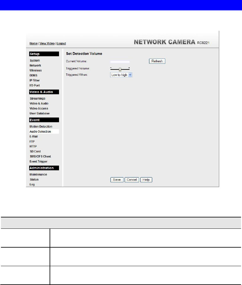
This screen is displayed when the Audio Detection option on the Event menu is clicked.
.
Figure 39: Audio Detection Screen
Data - Audio Detection Screen
Audio Detection
Current
Volume It displays the current volume of the environment. Click Refresh to
update the status.
Triggered
Volume Drag the bar to set the volume for triggering.
Triggered
When Choose the desired situation for triggering the audio detection.
56
E-Mail Screen
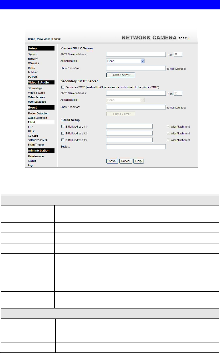
This screen is displayed when the E-Mail option on the Event menu is clicked.
.
Figure 40: E-Mail Screen
Data - E-Mail Screen
Primary/Secondary SMTP Server
SMTP Server
Address Enter the address of the SMTP (Simple Mail Transport Protocol)
Server to be used to send E-Mail.
Authentication Select the desired Authentication type for the SMTP Server.
SMTP Login name Enter your login name for the SMTP Server.
SMTP Password Enter your password for the SMTP Server.
POP server name Enter the name for the POP Server.
Show "From" as Enter the E-Mail address to be shown in the "From" field when the
E-Mail is received.
Test the Server Click this button to test the server connection.
Secondary SMTP Check the box to upload to the Secondary SMTP if the camera can
not connect to the primary SMTP.
E-Mail Setup
E-mail Address Enter at least one (1) E-Mail address; the 2nd and 3rd addresses are
optional. The E-Mail alert will be sent to the E-Mail address or
addresses specified here.
With Attachment Enable the checkbox if you want to attaché files to the E-mail.

57
Subject Enter the desired text to be shown as the "Subject" for the E-Mail
when it is received. Subject can not exceed 48 alphanumeric
characters.
58
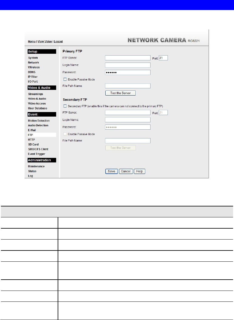
FTP Screen
This screen is displayed when the FTP option on the Event menu is clicked.
Figure 41: FTP Screen
Data - FTP Screen
Primary/Secondary FTP
FTP Server Enter the address of the FTP Server.
Port Enter the Port of the FTP Server to be connected.
Login name Enter your login name for the FTP Server.
Password Enter your password for the FTP Server.
Enable Passive
Mode Check the box to enable the Passive mode feature of the FTP.
File Path Name Enter the file path/name of the FTP.
Test the Server Click this button to test the server connection.
Secondary FTP Check the box to upload to the Secondary FTP if the camera can not
connect to the primary FTP.
59
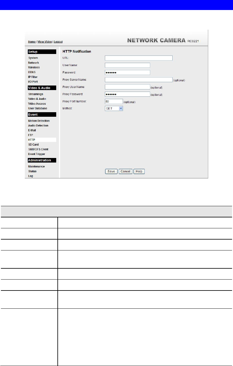
HTTP Screen
This screen is displayed when the HTTP option on the Event menu is clicked.
Figure 42: HTTP Screen
Data - HTTP Screen
HTTP Notification
URL Enter the URL of your HTTP notification server.
User Name Enter the user name of your HTTP server.
Password Enter the password to match the user name above.
Proxy Server
Name Specify the proxy server name in the provided field if the camera
needs to pass through a Proxy Server to do the HTTP notification.
Proxy User Name Enter the user name for the proxy server.
Proxy Password Enter the password for the proxy server.
Proxy Port
Number Enter the port number for the proxy server.
Method Select the desired method of form data encoding.
Get - It should be used if and only if the form processing is
independent, which typically means a pure query form.
Generally it is advisable to do so.
Post - If there are problems related to long URLs and non-ASCII
character repertoires, which can make it necessary to use
"POST" even for independent processing.
60
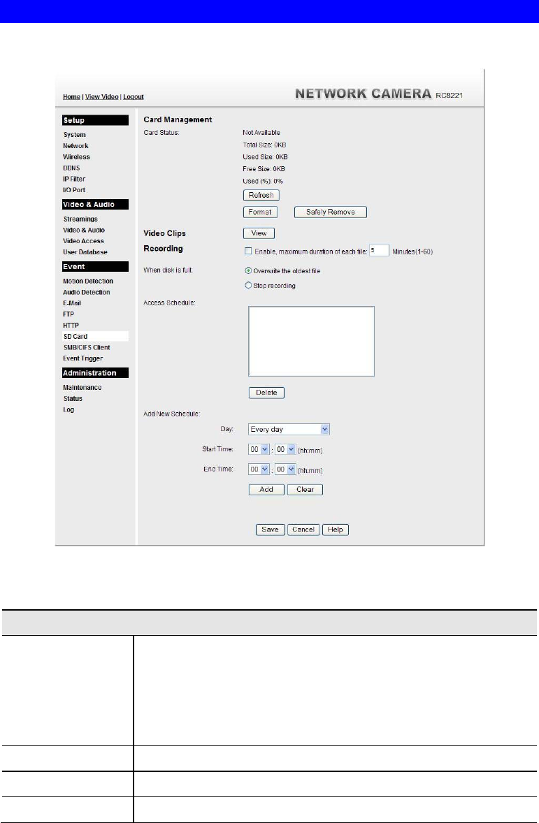
SD Card Screen
This screen is displayed when the SD Card option is clicked.
Figure 43: SD Card Screen
Data - SD Card Screen
Card Management
Card Status It shows details of the card, if any.
Total Size
Used Size
Free Size
Used (%)
Refresh Click this button to update the status of the current SD card
Format Format the SD card by clicking the Format button.
Safely Remove When you want to remove the card, click this button.

61
Video Clips Click View button to see the details of the video clips.
Recording
Enable Check the box if you want to enable recording function. Enter the
desired time (minute) to set the maximum time period of a recording.
When disk is full Select the desired option for the behavior when the disk space limit
is reached.
Overwrite oldest file. The Recorder will overwrite the oldest
file if the space is not enough for further recording.
Stop recording. If the disk space limit is reached, no further
recording is done.
Access Schedule
Scheduled Periods This displays all periods you have entered into the database. If you
have not entered any periods, this list will be empty.
Delete Use the Delete button to delete the selected item in the list.
Add New Schedule
Day Choose the desired option for the period.
Start Time Enter the start time using a 24 hr clock.
End Time Enter the end time using a 24 hr clock.
Add Click this button to add a new period.
Clear Use this button to clear the input fields.
62
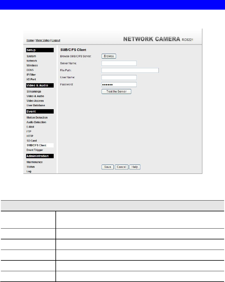
SMB/CIFS Client Screen
This screen is displayed when the SMB/CIFS Client option on the Event menu is clicked.
Figure 44: SMB/CIFS Client Screen
Data - SMB/CIFS Client Screen
SMB/CIFS Client
Browse SMB/CIFS
Server Click Browse button to select the desired SMB/CIFS server.
Server Name Enter the name of your SMB/CIFS server.
File Path Enter the file path of your SMB/CIFS server.
User Name Enter the user name for the SMB/CIFS client account.
Password Enter the password for the SMB/CIFS client account.
Test the Server Click this button to test the server connection.
63
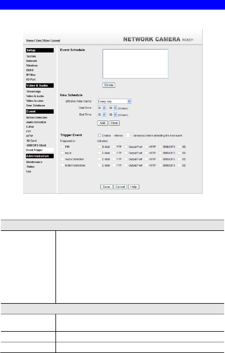
Event Trigger Screen
This screen is displayed when the Event Trigger option is clicked.
Figure 45: Event Trigger Screen
Data - Event Trigger Screen
Event Schedule
Schedule List The Event Schedule shows all of the event types currently
configured in the Network Camera, along with various information
about their configuration, as listed below:
Name - the descriptive event name set by the user.
Effective Time Frame - shows when the event at a set time will
be triggered.
Trigger by - shows what kind trigger activate the event.
Action - shows what kind of the actions will be issued when the
event been triggered.
New Schedule
Effective Time
Frame Choose the desired option for the period.
Start Time Choose the desired start time using a 24 hr clock.
End Time Choose the desired end time using a 24 hr clock.

64
Trigger Event
Enable Check to perform all of the event(s) that were configured and
scheduled.
Interval Select the desired option for the events interval. (* "0" = No Delay)
Trigger by PIR - If the PIR sensor detects a human body, it will be used to
trigger events.
Input - This describes the states that the input must be in for an
event to be triggered. Only one input can be used, also note that
the states for the input used must first be reached before the
event will be triggered.
Audio Detection - The sound detection can be used to trigger
events.
Motion Detection - Movement in a motion detection window
can be used to trigger events.
Actions E-Mail - If checked, an E-Mail (with "Attachment") will be
delivered to the SMTP server. (SMTP Server must be
configured on the E-Mail page.)
FTP - If checked, an FTP upload will be activated to the FTP
server. (FTP servers must be configured on the FTP page.)
Output Port - If checked, the output port state will be activated
as configured. (Output port must first be configured on the I/O
Port page.)
HTTP - If checked, a HTTP CGI command will be delivered to
the HTTP server.
SMB/CIFS - If checked, JPEG image(s) or video files will be
uploaded to the SMB server. (SMB must first be enabled and
configured on the SMB Client page.)
SD - If checked, the SD card state will be activated, and the avi
files will be saved in the SD card.
Attachment Type Streaming Channel - Select the desired type for the video file.
Pre/Post Capture - Select the desired length. The size of the
file depends on this setting, and also the Video size and degree
of compression.
65
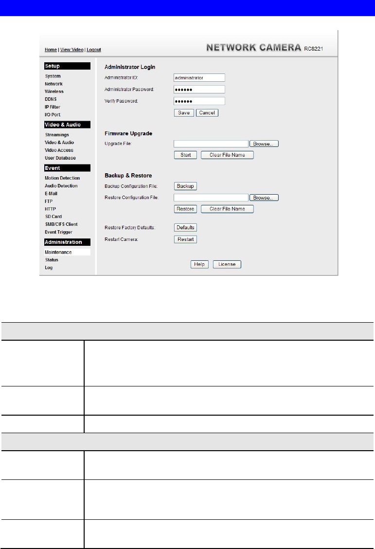
Maintenance Screen
.
Figure 46: Maintenance Screen
Data - Maintenance Screen
Administrator Login
Administrator
ID Enter the name for the Administrator here.
Spaces, punctuation, and special characters must NOT be used in the
name.
Administrator
Password The password for the Administrator.
Verify Password Re-enter the password for the Administrator, to ensure it is correct.
Firmware Upgrade
Upgrade File Click the "Browse" button and browse to the location on your PC
where you stored the Firmware file. Select this file.
Start Click this button to start the Firmware. When the upgrade is finished,
the Network Camera will restart, and this management connection will
be unavailable during the restart.
Clear File Name This does NOT stop the Upgrade process if it has started. It only clears
the input for the "Upgrade File" field.

66
Backup & Restore
Backup
Configuration
File
Click Backup button to save the current configuration information to a
text file.
It is suggested to backup the configuration file, in order to restore the
camera easily.
Restore
Configuration
File
Click Restore button to reinitialize the camera to load the new updated
software. Do this after loading the upgrade file.
Clear File Name This does NOT stop the Restore process if it has started. It only clears
the input for the "Restore Configuration File" field.
Restore Factory
Defaults Click Defaults button to reloads all default settings on the camera.
Restart Camera Click Restart button to restarts the camera.
67
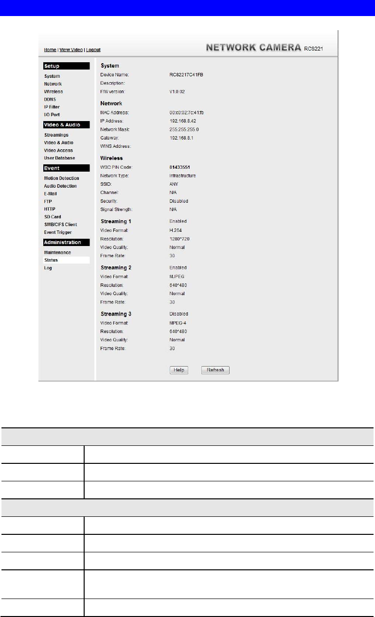
Status Screen
.
Figure 47: Status Screen
Data - Status Screen
System
Device Name This shows the name of the Network Camera.
Description This shows the description of the Network Camera, such as location.
F/W version The version of the current firmware installed.
Network
MAC Address The current IP address of the Network Camera.
IP Address The IP Address of the Network Camera.
Network Mask The network mask associated with the IP address above.
Gateway The IP Address of the remote Gateway associated with the IP Address
above.
WINS Address The IP Address of the WINS server.

68
Wireless
WSC PIN Code It displays the current WSC PIN code.
Network Type This shows the Network Type currently in use (Ad-hoc or
Infrastructure).
SSID This displays the wireless SSID.
Channel This shows the wireless channel currently used.
Security The current security setting for Wireless connections.
Signal Strength This shows the strength of the signal.
Streaming (1~3)
Video Format It displays the current format of video.
Resolution The image size of the video stream.
Video Quality This displays the image quality of the video stream.
Frame Rate This displays the frame rate of the video stream.
Buttons
Refresh Update the log and any other data on screen.
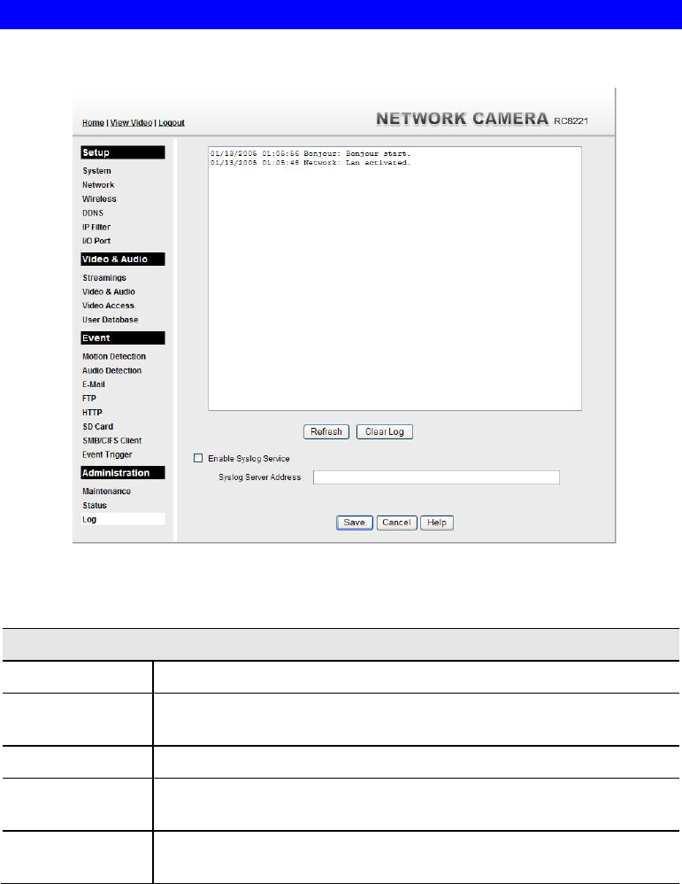
69
Log Screen
This screen displays a log of system activity.
.
Figure 48: Log Screen
Data - Log Screen
Log
System Log This is a log of system activity.
Refresh
Button Click this to update the data shown on screen.
Clear Log Click this button to restart the log.
Enable Syslog
Service Check the box to enable the System Log Server feature.
Syslog Server
Address Enter the address of the Syslog Server.

70
Chapter 6
Windows
Viewing/Recording Utility
This Chapter describes how to use the supplied Utilities package to view and
listen the live streams generated by the Network Camera.
Overview
The Utilities package includes following three functions:
LiveView - to view/listen the live streams.
View Recordings - to record the live streams.
Setup - to configure the Utilities such as adding camera, making recording schedules and
setting required parameters, etc..
The Utilities must be installed in the Windows before they can be configured.
System Requirements
In order to use the utility of Network Camera, you need to meet the following requirements:
Windows XP SP3, 32-bit Windows Vista/Windows 7.
Microsoft .NET Framework 3.5 Service Pack 1 (it should be installed on Windows
XP/VISTA via "Windows Update").
Internet Explorer 6 or later, Firefox 3.0 or later
2GB RAM
Individual Graphic Card
Installation
1. Insert the supplied CD-ROM into your drive. If the setup program does not start
automatically, run NetworkCamera.exe in the root folder. You will see the Welcome
screen shown below.
6
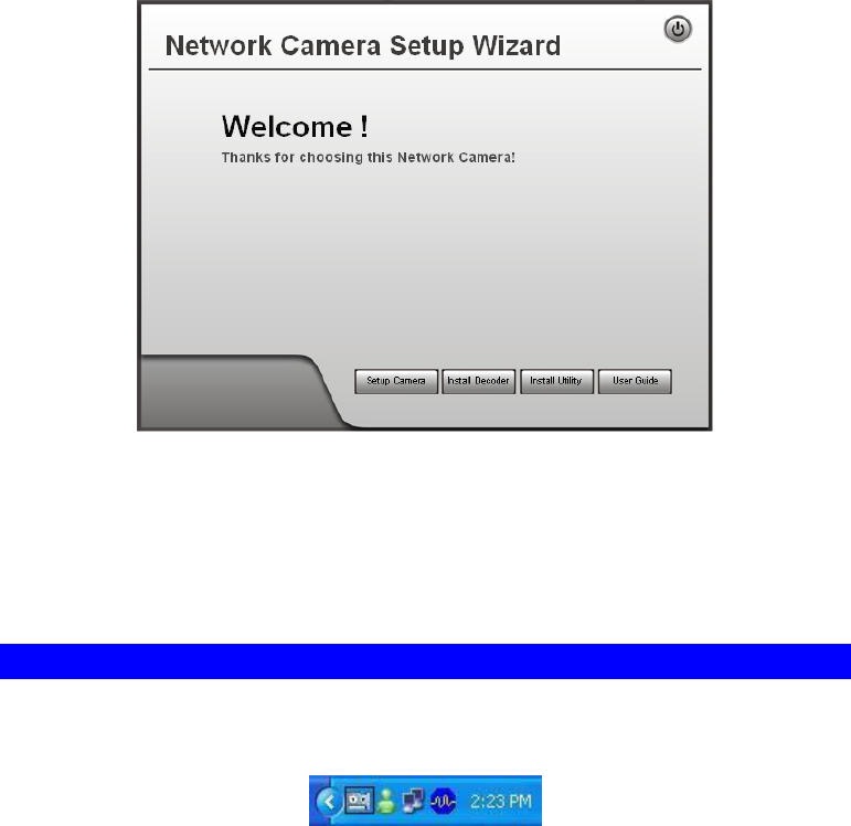
71
Figure 49: Welcome Screen
2. Click the Install Utility button to start the installation of the Utilities package.
3. Follow the prompts to complete the installation.
4. After the installation, double click the Monitor icon on the desktop or click Monitor menu
item in the Windows main program menu to launch the Utilities.
System Tray Icon
When started, the program will create an icon in the Windows system tray on the taskbar, as
shown below.
Figure 50: System Tray Icon
You can right click the icon and it will provides a menu which allows you to launch utility
program, view the utility details or even exit the utility package.
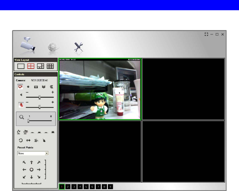
72
LiveView Screen
When Utility launched, the Camera Utility screen like the example below will be displayed.
Figure 51: Main Screen
If no cameras have been defined and added to the Utilities, no video will be displayed. Utilities
should be configured first to view the camera streams. See the following section for
information on defining a camera. Note that each Camera is given a number (Channel Number).
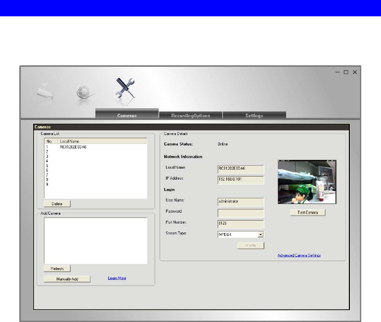
73
Camera Setup
To define a camera and associate it with a Channel Number:
1. Click the Setup icon on the main screen. You will see a screen like the example below.
Figure 52: Cameras Setup Screen
2. Add desired Network Camera to the Camera List:
To associate a camera automatically with the current Channel:
The Utilities will search and display all available Network Cameras found on
your LAN in the Add Camera list automatically. The Add Camera list can be
updated by clicking the Refresh button.
The Camera Details panel, on the right, displays the data for the selected camera.
Check that the Camera Details shown on the right is correct. Enter associated
User Name and Password.
Note: The Port Number, User Name, Password and Stream Type can only be
modified in the WEB UI instead of Camera Setup screen.
Click the Test Camera button to check that a connection and login can be
performed successfully.
Click Add button. The camera will now appear in the Camera List.
To associate a camera manually with the current Channel:
Click Manually Add button.
Enter the Local Name, IP Address, User Name, Password, Port Number and
Stream Type in the Camera Details section.
Note: The Port Number, User Name, Password and Stream Type can only be
modified in the WEB UI instead of Camera Setup screen.

74
Click the Test Camera button to check that a connection and login can be
performed successfully.
Click Add button. The camera will now appear in the Camera List.
Cameras Data
Camera list This displays the cameras you've added, if any. Use the Delete button to
delete the selected camera in the list.
Add cameras This list displays all available Network Cameras found on your LAN.
Address If you cannot find the desired camera in the above list, you can add it
manually by entering the IP address in this field.
Camera Status This displays the current status of the selected camera.
Local Name This is the default name for the Wireless Network Camera, and can be
changed.
IP Address The current IP address of the Wireless Network Camera. Or enter the
Domain Name or Internet IP address of the desired Wireless Network
Camera.
Login The camera Administrator can require that users provide a username and
password before being allowed to view the live video.
If the Administrator has not enabled this option, the Login fields can
be left blank.
Otherwise, you must enter the User Name and Password allocated
to your by Administrator.
Port Number This will normally display "80". Only change this if requested to do so
by the Wireless Network Camera Administrator.
Stream Type Select the desired type from the drop-down list.
Delete Button Click this button to delete the selected camera in My camera list.
Refresh Button The Add cameras list can be updated by clicking the Refresh button.
Add Button Click the button to add the selected camera to the list.
Test Camera Check the connection of the selected camera by clicking this button.
Advanced
Camera
Settings
Click this link to connect to the Web UI of the Network Camera
immediately.

75
LiveVew Program - for Streams Live Viewing
You can view live video in the Monitor screen. The built-in software can let you view up to 9
cameras on a single computer screen at one central location.
The following table lists the icons displayed on the Monitor screen:
View Layout. Use this to select the number of Channels (Cameras) to be
displayed on screen. Up to 9 cameras can be displayed.
View. This indicates if the camera stream is being viewed.
Red indicates the configured camera is being viewed.
Gray indicates that no camera is configured or the configured camera is not
connected to the Monitor.
Instant Record. Click this to start recording the current stream. While
recording, this button will be red. To stop recording, click this button again.
Gray indicates no recording.
Red indicates recording is in progress.
Snapshot. Click this to take a still image of the current video stream. The
image format is BMP.
Mirror. Click this to have the image swapped left-to-right.
Flip Video. Click this to have the image swapped top-to-bottom.
Speaker On/Off. To turn On/Off the speaker volume for the camera in
focused viewport.
Microphone On/Off. To turn On/Off the audio upload function for the
camera in the focused viewport.
Volume. If Speaker/Microphone is enabled, you can click the icon, then
drag and drop to raise or lower the volume.
Zoom Camera. A digital zoom-in feature is available. Drag the slider bar
to the desired magnified rate in a viewport.
Day/Night Mode. The Network Camera supports Day/Night mode switch
for getting better quality of the low light condition. This function is
available depending on the model of Network Camera.
IO Port 1/2. It indicates if there is any I/O type triggered event detected in
the port 1/2.
Patrol. Move through the Preset positions in the sequence defined by the
Camera Administrator.
Camera Auto Pan. Click this to have the camera moved from left to right
automatically.
Motion Detection. Click this button to have the camera moved to the
Motion Detection Preset position.
Direct P/T. Use this to move the camera to the Pan/Tilt position directly.
Preset Points. Select the desired Preset points.

76
Move Control. Use this to move the camera to the desired position. There
may a short delay after clicking the desired icon. You should wait a couple
of seconds rather than click again.
Or you can drag the vertical or horizontal slider bar to have quicker
movement of the Network Camera to the desired position.
Setup. Click this button to open the Utilities configuration program.
View Recordings. Click this button to launch the recording program, which
allows you to browse through the previously saved recordings. Please see
the " View Recordings Program - for Streams Recording " section for
details.
Channel Indicator. This indicates the current channel (camera).
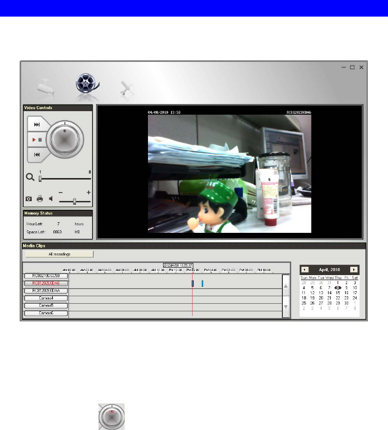
77
View Recordings Program - for Streams Recording
To access the saved recordings of the Cameras, click View Recordings icon on the top of the
screen, then you will see a screen like following.
Figure 53: View Recordings Screen
Searching Recorded Streams Files
Skip to Next Record. Use this to view the next available record.
Play. Use this to re-start viewing, after using the Pause button.
Playing speed. Use the
to accelerate (right) or decelerate (left) the playing speed.
Pause. Use this to temporarily stop playing.
Skip to Previous Record. Use this to view the previous record.
Zoom In. To zoom in on a section of the window, drag the slider bar to the desired magnified
rate of a viewport.
Snapshot. Click this to take a still image of the current video.
Print. Click this to print the current frame which is showing in the screen.
Speaker. To play a recorded file, select the desired volume.
Hour Left. It displays the possible available time for recording.
Space Left. It displays the current available space of the memory.
All recordings. Click this button to select the type (All recordings or Event recordings) of the
recorded files.
Select Camera. Click the desired camera to find the recordings.
78
Recording Bar. It displays the recordings that match your requests.
Calendar. Choose the date of the calendar for finding desired recordings.
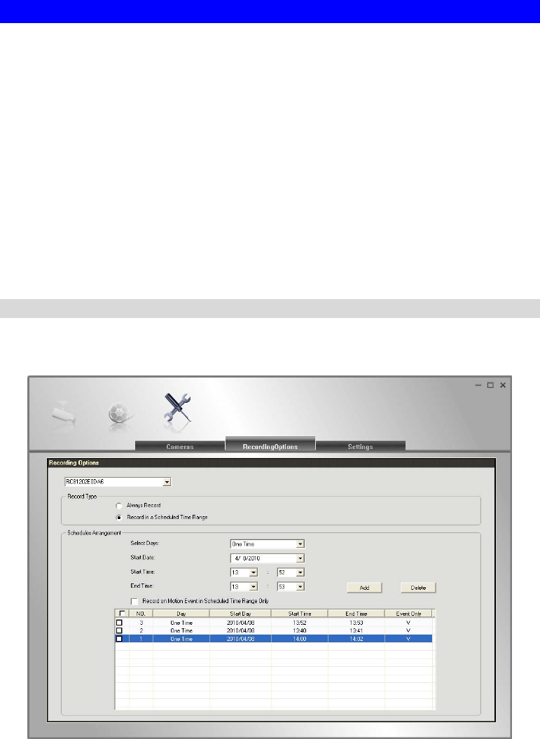
79
Setup Program - for Streams Configuration
There are 3 tabs of the Setup program:
Cameras
Recording Options
Settings
For the Cameras configuration, please refer to the Camera Setup for details.
You can record the streams from camera by pressing the Instant Record button in the Monitor
program as mentioned in the " LiveVew Program - for Streams Live viewing" section or by
making schedules to let the recording happen on the arranged time period.
All the recorded streams are stored in files with a proprietary format and can be viewed via
Playback program in the Utilities package.
If you want to change the default settings of recording parameters before doing any recording,
please see the "Settings" section for details.
Recording Options
To make recording schedules, click the Recording Options tab on the Setup screen. You will
see a screen like the example below.
Figure 54: Recording Options
If necessary, change these settings to suit your environment. Please follow the steps below to
make a schedule for recording:
1. Select a camera from the available camera list.
2. Select either Always Record or Record in a Scheduled Time Range for recording type.
3. If Record in a Scheduled Time Range is selected, set the recording time range from Start
Date, Start Time and End Time boxes.
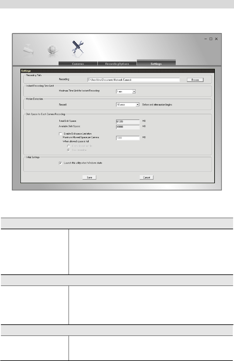
80
4. Press Add button to add the schedule.
You will see all the schedules in the recording list.
Settings
Clicking the Settings tab on the Configuration program to make change of default Utilities
parameter settings.
Figure 55: Settings Screen
Data - Settings
Recording Path
Recording This is the Drive and Folder on your PC/Notebook where
recorded files will be placed. You need a drive which has large
amounts (Gigabytes) of free space. Click the Browse button to
select the drive and folder if you want to change the default
path. Note that file names for the recordings are automatically
assigned, using an internal date-time coding rule.
Instant Recording Time Limit
Maximum Time Limit
for Instant Recording This sets the maximum time period of a recording which is
started by clicking the Record button on the Monitor main
screen. If the recording is not stopped manually before the
arranged time period elapsed, it will be terminated automatically
when the end time hit.
Motion Detection
Record Before and
after motion begins Set the time so that the Recorder will make a pre-recording and
post-recording for at most the specified time range while a
motion begins and ends.

81
Disk Space for Each Camera Recording
Total Disk Space This displays the total size of the selected disk.
Available Disk Space This displays the available space of the selected disk for storing
recordings.
Enable Disk space
limitation Enable this if you wish to limit the disk space used by video
recordings.
Maximum Allowed
Space per Camera Enter the maximum amount of disk space assigned to each
camera for stream recordings.
When allowed space
is full. Select the desired option for the behavior when the disk space
limit is reached.
Overwrite earliest file. The Recorder will overwrite the
oldest file if the space is not enough for further recording.
Stop Recording. If the disk space limit is reached, no
further recording is done.
Initial Settings
Launch this utility
when Windows starts Check this to have this utility start when Windows starts.

82
Chapter 7
Troubleshooting
This chapter covers the most likely problems and their solutions.
Overview
This chapter covers some common problems that may be encountered while using the Network
Camera and some possible solutions to them. If you follow the suggested steps and the
Network Camera still does not function properly, contact your dealer for further advice.
Problems
Problem 1: I can't connect to the Network Camera with my Web Browser to
configure it.
Solution 1: It is possible that your PC's IP address is not compatible with the IP
address of the Network Camera.
Use the Windows utility to configure the Network Camera with a valid IP
address.
Problem 2: The Windows utility doesn't list any Network Camera.
Solution 2: Check the following:
The Network Camera is installed, LAN connections are OK, it is
powered ON and startup is complete.
Ensure that your PC and the Network Camera are on the same network
segment. (If you don't have a router, this must be the case.)
Ensure that your PC has the TCP/IP network protocol loaded. In
Windows, this is done by using Control Panel-Network.
If an entry for TCP/IP -> Network card is not listed, use Add -
Protocol - Microsoft - TCP/IP to add it.
You then need to select the new entry (TCP/IP -> Network card),
click Properties, and configure the IP Address tab.
If your LAN has a DHCP Server, you can select "Obtain an IP
Address automatically". Otherwise, you must select "Specify an
IP Address", and enter values for IP Address, Subnet Mask, and
Gateway. All devices on your LAN must use compatible values.
Remember that each device needs a unique IP Address, and the
same Subnet Mask.
Problem 3 When I try to connect to the Network Camera, I get prompted for a
user name and password.
Solution 3 You SHOULD be prompted for a user name and password if trying to
access the Administration menu.
Enter the Administrator ID and Administrator Password set on the
Maintenance screen.
7
83
If you are just trying to view Video, the User Name/Password prompt
indicates that the Administrator has restricted access to specified users.
Ask the Administrator for your User Name and Password.
Problem 4 I can't connect to the Network Camera using a Wireless connection.
Solution 4 1) If a LAN cable is connected to the LAN port, the Wireless interface is
disabled. Only one interface can be active.
2) Check that your PC and the Network Camera have compatible Wireless
settings.
Mode (Infrastructure or Ad-hoc) must be correct.
ESSID must match.
WEP settings must match.
In Ad-hoc mode, the Channel should match, although this is often not
required.
Problem 5 Video quality may suddenly deteriorate.
Solution 5 This can happen when an additional viewer connects to the Network
Camera, overloading the camera or the available bandwidth. The image
size and quality can be adjusted to cater for the required number of viewers
and the available bandwidth.
Problem 6 The motion detection feature doesn't send me any E-mail.
Solution 6 It may be that the SMTP (Simple Mail Transport Protocol) server used by
the camera to send the E-Mail will not accept mail. (This is to prevent span
being sent from the server.). Try using a different SMTP server, or contact
your ISP to see if SMTP access is being blocked.
Problem 7 Using the motion detection feature, I receive E-Mails which don't show
any moving objects.
Solution 7 The motion detection feature doesn't actually detect motion. It compares
frames to see if they are different. Major differences between frames are
assumed to be caused by moving objects.
But the motion detector can also be triggered by:
Sudden changes in the level of available light
Movement of the camera itself.
Try to avoid these situations. The motion detection feature works best in
locations where there is good steady illumination, and the camera is
mounted securely. This feature can NOT be used if the camera is outdoors.
Problem 8 The image is blurry.
Solution 8 Try cleaning the lens, or adjusting the Video Quality Control setting on the
Streamings screen. Video created by the lower settings will contain less
detail; this is the trade-off for using less bandwidth.
Problem 9 When is the best time to press WPS button?
Solution 9 If there is no cable connected, you can press the WPS button after the
Power LED starts blinking.
Problem 10 In some older Window XP systems, it may not be able to see
H.264/MPEG4 video streaming.
84
Solution 10 In order to view H.264/MPEG4 video streaming in the older Window XP
systems, please install the Microsoft .net framework 2.0 or later version, so
the system will be able to deploy the built-in H.264/MPEG4 decoder of the
camera.
Problem 11 I use the camera via IE browser in protected mode of Windows
Vista/7, there is no local recording/setup feature to be used.
Even if I run it with IE browser in non-protected mode of Windows 7,
the folder like "Windows" still can not be accessed. (There is no
recording files found in this folder as well)
Solution 11 There will be no local recording files and the setup service of associated
folder if the IE browser is in protected mode.
To use the local recording feature, please operate IE browser in
non-protected mode.
Note! Some folders (ex. ″Windows″ folder) with high integrity level can
not be accessed via non-protected mode of IE in Window 7.

85
Appendix A
Specifications
Network Camera
Model Network Camera
Dimensions 63mm (W) x 95mm (H) x 35mm (D)
Operating Temperature 0 C to 50 C
Video compression H.264, MPEG4 and MJPEG
Image resolution 1280x 720, 640x480 (720p system default), 320x 240 (QVGA),
160 x 120 (QQVGA)
Storage Temperature -20 C to 70 C
Network Protocols TCP/IP, HTTP, HTTPS, DHCP, NTP, SMTP, UPnP, FTP,
RTP/RTSP
Network Interface 1 Ethernet 10/100BaseT (RJ45) LAN connection
Wireless interface IEEE 802.11n/802.11b/802.11g compatible, Infrastructure/Ad-
hoc mode, WEP 64/128 bit, WPA/WPA2 personal security
support
LEDs 3
Micro-SD Card slot 1
Power Adapter 12V/1A, 100~240 VAC
Regulatory Approvals
FCC Statement
This equipment generates, uses, and can radiate radio frequency energy and, if not installed and
used in accordance with the instructions, may cause harmful interference to radio
communications. However, there is no guarantee that interference will not occur in a particular
installation. If this equipment does cause harmful interference to radio or television reception,
which can be determined by turning the equipment off and on, the user is encouraged to try to
correct the interference by one of the following measures:
Reorient or relocate the receiving antenna.
Increase the separation between the equipment and receiver.
Connect the equipment into an outlet on a circuit different from that to which the receiver
is connected.
Consult the dealer or an experienced radio/TV technician for help.
A

86
To assure continued compliance, any changes or modifications not expressly approved by the
party responsible for compliance could void the user's authority to operate this equipment.
(Example - use only shielded interface cables when connecting to computer or peripheral
devices).
FCC Radiation Exposure Statement
This equipment complies with FCC RF radiation exposure limits set forth for an uncontrolled
environment. This equipment should be installed and operated with a minimum distance of 20
centimeters between the radiator and your body.
This device complies with Part 15 of the FCC Rules. Operation is subject to the following two
conditions:
(1) This device may not cause harmful interference, and
(2) This device must accept any interference received, including interference that may cause
undesired operation.
This transmitter must not be co-located or operating in conjunction with any other antenna or
transmitter.
CE Approvals
The Network Camera and the Ethernet Network Camera meet the guidelines of the European
Union and comply with the 99/5/EEC and RTTE 99/5EG directives, including the following
standards:
EN60950
EN300 328
EN301 489-1
EN301 489-17
This is a Class B product. In a domestic environment this product may cause radio interference
in which case the user may be required to take adequate measures.
Copyright Notice
Many software components are covered by the GNU GPL (General Public License). Some are
covered by other Licenses.
You can check more details of each applicable license by clicking the License button in the
Maintenance screen.

87
Appendix B
Network Camera HTTP CGI
User-level CGI commands (user level privilege)
Notes: If camera is in privacy mode, it will reject the streaming/snapshot request with
“406 Not Acceptable” and stop video post for event.
Video and Image commands
Stream M-JPEG video
HTML page for the end user
Method: GET
URL: http://<ip>/img/mjpeg.htm
Return:
HTTP/1.0 200 OK\r\n
…
content-type: text/html\r\n
…
http://<ip>/img/video.mjpeg
…
B

88
Server Push page for the programmer
Method: GET
URL: http://<ip>/img/video.mjpeg (utility)
The camera will check the request User-Agent parameter in HTTP header to identify the
client type. The camera will regard the client as MSIE if there is the string “MSIE”, regard
the client as SerComm OCX if there are the strings “CameraActiveX” or “Viewer” or
“AlertCfg”, and regard others as PushServer.
Return (OK situation):
If the client is MSIE
HTTP/1.0 200 OK\r\n
…
content-type: image/jpeg\r\n
…
<MJPEG data>
If the client is SerComm OCX
HTTP/1.0 200 OK\r\n
…
<MJPEG video or AUDIO data>
The format of motion JPEG for OCX, to support the audio stream feature, we add an extra
header at begin of the stream data (mjpeg/audio) to describe the frame information and
sending status. The extra header contains 48 bytes in little-endian, the fields are shown as
following:
Location Parameter Value and description
0-3 Magic
String
The string to identify the header.
It must be "MJPG".
4-7 Frame Size The frame size. (bytes)
8-9 Width The JPEG width.
10-11 Height The JPEG height.
12-15 Sent Size The size of the sent frame. (bytes)
16-17 Slice Size The size of the slice. (bytes)
18-21 Timestamp The time stamp of the frame.
The time stamp of the first frame is always 0.
22 Frame
Type
The frame type.
0x01 (01): JPEG
0x02 (02): G.726 Audio|
0x03 (03): G.711 a law Audio
0x04 (04): G.711 u law Audio
0x05 (05): AMR Audio
0x10 (16): LPCM mono Audio at 8KHz Sample Rate

89
23-24 Bit Rate The audio bit rate.
0x02 (02): 2 KbytesPerSecond
0x04 (04): 4 KbytesPerSecond
0x08 (08): 8 KbytesPerSecond
25 Version The version number.
It is 0x02 (02).
26-45 Time
String
The ASCII string to present the current camera time. (Not
used)
46 Padding
flag
The padding flag
0x00: No padding data
0x01: There is the padding data at the end of the frame,
please refer to chapter “Padding data format” for details
47 Reserved Reserved
Example, A normal JPEG frame:
Image size is 5930, width is 320, height is 240, sent data size is 2000, slice size is 2000,
timestamp is 0, frame type is 1 (JPEG), version number is 1. The header will look like as
follows:
4D 4A 50 47 2A 17 00 00 40 01 F0 00 D0 07 00 00
D0 07 00 00 00 00 01 02 00 02 00 00 00 00 00 00
00 00 00 00 00 00 00 00 00 00 00 00 00 00 00 00
(2000 bytes JPEG data)
We will regard others client as the PushServer.
HTTP/1.0 200 OK\r\n
…
content-type: multipart/x-mixed-released;boundary=<xxx>\r\n
--<xxx>
content-type:image/jpeg\r\n
content-length: <image-size>\r\n\r\n
<jpeg image date>
--<xxx>
content-type:image/jpeg\r\n
content-length: <image-size>\r\n\r\n
<jpeg image date>
...
--<boundary>--
Return (ERROR situation):
HTTP/1.0 400 Bad Request\r\n

90
…
content-type: text/plain\r\n
\r\n
current_ resolution=A\r\n
current_framerate=B\r\n
The A and B are in the following format.
Parameter Value and description
A Image resolution
1: 160x120 (or 160x128, 176x120 (NTSC)/ 176x144(PAL),
depends on models)
2: 320x240 (or 352x240(NTSC)/ 352x288(PAL), depends on
models)
3: 640x480 (or 704x480(NTSC)/ 704x576(PAL), depends on
models)
4: 1280x960 (depends on models)
B Frame rate 1 ~ 30fps
Snapshot
Method: GET
URL: http://<ip>/img/snapshot.cgi?[size=<value>][&quality=<value>]
Parameter Value and description
size Image resolution
1: 160x120 (or 160x128, 176x120 (NTSC)/ 176x144(PAL),
depends on models)
2: 320x240 (or 352x240(NTSC)/ 352x288(PAL), depends on
models)
3: 640x480 (or 704x480(NTSC)/ 704x576(PAL), depends on
models)
4: 1280x720 (depends on models)
quality Quality level
1: Very high
2: High
3: Normal
4: Low
5: Very low
Example 1: To snapshot a 640x480 (or 704x480(NTSC)/ 704x576(PAL), depends on models)
very high quality JPEG image from network camera 192.168.0.99.
http://192.168.0.99/img/snapshot.cgi?size=3&quality=1
Example 2: To snapshot a JPEG image from network camera 192.168.0.99 (with current
resolution and quality)
http://192.168.0.99/img/snapshot.cgi
Example 3: To snapshot a low quality JPEG image with current resolution from the network
camera 192.168.0.99.
http://192.168.0.99/img/snapshot.cgi?quality=4
Return: A JPEG image will be returned to client with user specified resolution and quality.
HTTP/1.0 200 OK\r\n

91
…
content-type: image/jpeg\r\n
…
<JPEG image data>
SDP (MPEG-4/H.264 video/MJPEG)
Method: GET
URL: http://<ip>/img/media.sdp
Return: A SDP file will be returned.
HTTP/1.0 200 OK\r\n
…
<SDP data>
Audio Upload (uploading audio streaming to the camera)
Method: POST
URL: http://<ip>/img/g726.cgi G.726 audio stream (16Kbps or 32Kbps,
depends on models)
URL: http://<ip>/img/g711a.cgi G.711 a-law audio stream (64Kbps)
URL: http://<ip>/img/g711u.cgi G.711 u-law audio stream (64Kbps)
Example (client side):
POST /IMG/g726.cgi HTTP/1.0\r\n
Host: 192.168.0.99\r\n
Return:
OK
HTTP/1.0 200 OK\r\n
Client starts to upload the audio stream.
Unauthorized (Bad username, password)
HTTP/1.0 401 Unauthorized\r\n
RTP/RTSP
User can stream video and audio through the following URLs.
Video and audio: rtsp://<ip>/img/media.sav
Video only: rtsp://<ip>/img/video.sav
Audio only: rtsp://<ip>/img/audio.sav
If the client player is QuickTime player, there are always around 3 seconds latency. If
there is not audio content in the streaming, you can use the extension parameter
“[?|&]latency=no” to push QuickTime player to play the streaming without any latency,
but this method causes the frame rate is not stable. Example:
rtsp://<ip>/img/video.sav?latency=no
92
Note that camera is able to support the following four RTP protocols. But user needs to
specify the desired RTP protocol in the player.
1. Unicast RTP
2. Multicast RTP
3. RTP over RTSP (RTP over TCP)
4. RTP over RTSP over HTTP (HTTP tunnel)
Return: Video and/or audio will be returned.

93
SWF/FLV
Method: GET
URL: http://<ip>/img/media.swf
Return: Action script content to trigger the player to get the media content.
HTTP/1.0 200 OK\r\n
…
<data>
Method: GET
URL: http://<ip>/img/media.flv
Return: media content.
HTTP/1.0 200 OK\r\n
…
<data>
Extension to the streaming URL defines
We extend some parameters for some products which support the multiple streamings
simultaneously.
Related URLs:
video.asf, video.mjpeg, mjpeg.cgi, snapshot.cgi, media.sdp, media.sav, video.sav
Extension syntax:

94
Parameter Description
channel If the product supports multiple streaming channels
simultaneously, we will append the parameter
“[?|&]channel=[1|2|...]” to identify, example:
To view the 1st channel streaming: video.sav or
video.sav?channel=1
To view the 2nd channel streaming:
video.sav?channel=2
video If the product supports multiple video codec simultaneously,
we will append the parameter
“[?|&]video=[MPEG4|MJPEG|H264]” at the end of original
URL to identify, example:
To view streaming with MPEG4 video:
video.sav?video=MPEG4
To view streaming with H264 video:
video.sav?video=H264
Mix the
parameters
channel and
video
If the product supports multiple streaming channels and
multiple video codec at one video channel simultaneously, we
will append both channel and video parameters to identify, the
parameter “channel” is the main key with priority.
Response error if parameters are not correct.
If only “channel” parameter provided, stream the
default video, priority is: MPEG4, MJPEG, H264.
If none parameter provide, use the default channel
number, and then stream the video by priority channel 1,2,3…
If only “video” parameter provided, stream the video
from the channel supports, use the default channel number, and
then priority is: 1,2,3,…
Example#1:
Total is 3 channels, the 1st channel has H264 video
and the 2nd channel has MPEG4 video, the 3rd channel has
MJPEG video, default viewer channel is 1st, then:
To view the H264 (or to view the 1st channel video):
video.sav?channel=1 or
video.sav?video=H264 or
video.sav?channel=1&video=H264
To view the MPEG4 (or to view the 2nd channel
video):
video.sav?channel=2 or
video.sav?video=MPEG4 or
video.sav?channel=2&video=MPEG4
To view the MJPEG (or to view the 3rd channel
video):
video.mjpeg
Example#2:
Total is 3 channels, the 1st channel has H264 video

95
and the 2nd channel has H264 video, the 3rd channel has
MJPEG video, default viewer channel is 1st, then:
To view the H264 at 1st channel:
video.sav?channel=1&video=H264 or
video.sav?video=H264
To view the H264 at 2nd channel:
video.sav?channel=2&video=H264
Have not MPEG4 video for viewing.
To view the MJPEG:
video.mjpeg
Example#3 (not supported in product spec yet):
Total is 2 channels, the 1st channel has H264 video
and the 2nd channel has H264 & MPEG4 videos, default viewer
channel is 1st, then:
To view the H264 at 1st channel:
video.sav?channel=1&video=H264
To view the H264 at 2nd channel:
video.sav?channel=2&video=H264
To view the MPEG4 at 2nd channel:
video.sav?channel=2&video= MPEG4 or
video.sav?video=MPEG4
padding If the product supports padding data over the streaming, such
as motion information, we will append the parameter
“[?|&]padding=[no|yes]” to identify, default (no this parameter)
depends on products and streaming types. Example:
To view the streaming without padding data:
video.sav?padding=no
To view the streaming with padding data:
video.sav?padding=yes
* You can refer to the section 2.11 for more
details.
Player commands
Query
Method: GET
URL: http://<ip>/util/query.cgi[?extension=value]
This CGI indicates the H/W capability, component setting. Ex: The camera got I/O port
(or not). The camera got Speaker (or not), etc.

96
Parameter Value and description
extension Extension value
yes: extension is enabled, the extended data as below will be
extended to generic response.
fw_ver=V1.0.0R44\r\n
ip_addr=192.168.1.12\r\n
netmask=255.255.255.0\r\n
gateway=192.168.1.1\r\n
current_time=07/02/2008 10:12:10\r\n -> MM/DD/YYYY HH:MM:SS
24-Hour format
timezone=4\r\n
http_port=80\r\n -> The value is -1 or none this parameter
indicate the HTTP disabled.
https_port=443\r\n -> The value is -1 or none this parameter
indicate the HTTPS disabled.
rtsp_port=554\r\n
Return:
HTTP/1.0 200 OK \r\n
…
content-type: text/plain\r\n
\r\n
<parameter pair>\r\n
<parameter pair>\r\n
......
Here are the details of parameter pairs:
Parameter Value and description
hostname Camera name, example: sc123456
description Camera description, example: Hello camera
defname Camrea default name, example: default name
mac Camera's MAC address, example: 00C002123456
company_name Camera's comany name, example: SerComm
model_number Camera's model number, example: RC8020
resolutions Phase out in new projects. The resolutions camera support, depends
on models, valid values:
[1280*960,640*480,320*240,160*120|704*480,352*240,176*120|7
04*576,352*288,176*144]

97
mpeg4_resolutio
n Current MPEG-4 resolution setting, depends on models, valid values:
[1280|640|320|160|704|352|176]
For multiple streaming channels, use the keys: mpeg4_resolution,
mpeg4_resolution2, …
Won't provide this paramter if there is not such video format enabled
or supportted.
mjpeg_resolutio
n Current JPEG resolution setting, depends on models, valid values:
[1280|640|320|160|704|352|176]
For multiple streaming channels, use the keys: mjpeg_resolution,
mjpeg_resolution2, …
Won't provide this paramter if there is not such video format enabled
or supported.
h264_resolution Current H.264 resolution setting, depends on models, valid values:
[1280|640|320|160|704|352|176]
For multiple streaming channels, use the keys: h264_resolution,
h264_resolution2, …
Won't provide this paramter if there is not such video format enabled
or supported.
mic_in Current MIC in setting, valid values: [on|off]
speaker_out Current Speaker out setting, valid values: [on|off]
audio_duplex_
mode Only valid for the products have such setting feature in Web UI.
Current audio duplex mode setting, only “off” is valid, example:
Talk only:
mic_in=off, speaker_out=on
Listen only:
mic_in=on, speaker_out=off
Talk & Listen duplex:
mic_in=on, speaker_out=on
Talk & Listen half:
mic_in=on, speaker_out=on,
audio_duplex_mode=off
ptctrl PT HW capability, valid values: [on|off]
ioctrl IO HW capability, valid values: [on|off]
serial RS485 capability, valid values: [pelco|off]
privacy_button Privacy button HW capability, valid values: [on|off]
pir_sensor PIR sensor HW capability, valid values: [on|off]
wlled White light LED HW capability, valid values: [on|off]
irled IR LED HW capability, valid values: [on|off]
wps_pin_code WPS PIN code value, example: 00000048

98
wireless Wireless HW capability, example: [on|off]
sw_pppoe PPPoE software feature capability/supported, valid values: [yes|no]
URL: http://<ip>/img/query.cgi
This CGI indicates the accessed user's privilege with some H/W features. Ex. The user
could use Speaker Out, but couldn't control the I/O ports, etc.
Return:
HTTP/1.0 200 OK \r\n
…
content-type: text/plain\r\n
\r\n
mic_in=[on|off]r\n
speaker_out=[on|off]\r\n
ptctrl=[on|off]\r\n
ioctrl=[on|off]\r\n
interlace=[0|1]\r\n(only for analog CCTV input)

99
Query/Control the peripheral components status (Operator,
combination CGI)
Notes: This combination CGI command will replace the separated peripheral control
CGIs.
Query the peripheral components status
Method: GET
URL: http://<ip>/io/query_pc.cgi[?<parameter>[&<parameter>...]]
Input parameters:
None parameter provided, CGI responds all supported peripherals' status.
The peripheral parameter provided, CGI just responds the specific peripherals'
status. Please refer to the “Parameter Pairs Table” for specific input parameters.
Return:
HTTP/1.0 200 OK \r\n
…
content-type: text/plain\r\n
\r\n
<parameter pair>\r\n
<parameter pair>\r\n
......
Here are the details of parameter pairs, parameters depend on product models.
“error” value response indicate that “Failed to query/control the peripheral
equipments”
Parameter Pairs Table
Parameter Get/Set Value and description
privacy_button Query
only Privacy button status, valid values: [disabled|off|on]
pir Query
only PIR status, valid values: [disabled|actionless|active]
light_sensor Query
only Light sensor status, valid values: [disabled|night|day]
pt_position Query
only Query current Pan & Tilt position, because the MCU can’t get
response from PT, so the values maybe wrong under some
conditions. Format is “X,Y”
“X” is the Pan position; “Y” is the Tilt position.
input_1
input_2
Query
only Input #1,#2 status, valid values: [high|low]
output_1
output_2
Get &
Set
Onput #1,#2 status,
Query format is “A,B”.
“A” valid values: [high|low]
“B” valid values: [pulse|static]
Control format is “A”.
“A” valid values: [high|low]

100
dn_mode Get &
Set
Day/Night mode status, valid values: [day|night]
Day mode, IR LED off, IR cut switch close the window to
filter the IR lights.
Night mode, IR LED on, IR cut switch open the window not
to filter the IR lights.
ir_cut Get &
Set
IR cut switch status, valid values: [close|open]
ir_leds Get &
Set
IR LEDs status, valid values: [disabled|off|on], disabled is
only valid for query CGI
wl_leds Get &
Set
White light LEDs status, valid values: [disabled|off|on],
disabled is only valid for query CGI
Control the peripheral components status
Method: GET
URL: http://<ip>/io/control_pc.cgi?<parameter>=<value>[&<parameter pair>…]
Parameter Value and description
Please refer to the “Parameter Pairs Table”
Return:
Successful request returns all group parameters or the specified parameters as below.
HTTP/1.0 200 OK\r\n
…
content-type: text/plain\r\n
...
\r\n
OK\r\n

101
Query IR cut switch status
Method: GET
URL: http://<ip>/io/query_filter.cgi
Return: Network Camera will return a Web page that contains the following messages.
HTTP/1.0 200 OK \r\n
…
content-type: text/plain\r\n
\r\n
filter=[0|1]\r\n <- 0= Close the window; 1= Open the window
\r\n

102
Admin-level CGI commands (administrator level privilege)
Query FW version
Method: GET
URL: http://<ip>/adm/sysinfo.cgi
Return: Network Camera will return a Web page that contains the following messages.
HTTP/1.0 200 OK \r\n
…
content-type: text/plain\r\n
\r\n
Firmware Version: V1.0.01\r\n
Serial Number: SQJ00G100001\r\n
Reboot
Method: GET
URL: http://<ip>/adm/reboot.cgi
Return:
HTTP/1.0 200 OK \r\n
…
content-type: text/plain\r\n
\r\n
OK\r\n
Restore to factory defaults
Method: GET
URL: http://<ip>/adm/reset_to_default.cgi
Return:
HTTP/1.0 200 OK \r\n
…
content-type: text/plain\r\n
\r\n
OK\r\n

103
Query/Control the peripheral components status
Start/Stop the camera privacy mode
Method: GET
URL: http://<ip>/adm/privacy_ctl.cgi?privacy=<parameter>
Parameter Value and description
start start: camera enter privacy mode. Any user can't view the video any more.
stop stop: camera end the privacy mode.
Return:
Successful request returns all group parameters or the specified parameters as below.
HTTP/1.0 200 OK\r\n
…
content-type: text/plain\r\n
...
\r\n
OK\r\n
Get/Set group parameters
Get group parameters
Method: GET
URL: http://<ip>/adm/get_group.cgi?<parameter>=<value>[&<value>…]
Parameter Value and description
group 1. To get all group settings
group_name (The group name is case insensitive.)
2. To get a specific setting from a group
group_name.parameter_name
3. To get the settings from multiple groups
group_name&group_name...
Note that all group_name and parameter_name are defined in the
Network Camera Configuration Spec
Return:
All group settings or one group setting will be returned as below.
HTTP/1.0 200 OK\r\n
…
content-type: text/plain\r\n

104
...
\r\n
[group1]\r\n
<parameter pair>\r\n
<parameter pair>\r\n
...\r\n
[group2]\r\n
<parameter pair>\r\n
<parameter pair>\r\n
...\r\n
Where <parameter pair> is <parameter_name>=<parameter_value>.
Set group parameters
Method: GET
URL: http://<ip>/adm/set_group.cgi?<parameter>=<value>[&<parameter pair>…]
Parameter Value and description
group Group name is specified here. (The group name is case insensitive.)
Note that all group values are defined in the Network Camera
Configuration Spec.
1. To set a specific setting in a group
group=group1&key=value...
2. To get the settings from multiple groups
group=group1&key=value...&group=group2&key=value...
Return:
Successful request returns all group parameters or the specified parameters as below.
HTTP/1.0 200 OK\r\n
…
content-type: text/plain\r\n
...
\r\n
OK\r\n

105
Get/Set System date and time
Method: GET
URL: http://<ip>/adm/date.cgi?action=<value>[&<parameter pair>…]
Parameter Value and description
action Get/Set the system date and time
get= Get the system date and time
set= Set the system date and time
time_zone The index value in time zone table (Readonly), please refer to
Network Configuration file Spec
year Year (2005~2037)
month Month (1~12)
day Day (1~31)
hour Hour (0~23)
minute Minute (0~59)
second Second (0~59)
Return:
Successful request returns all group parameters or the specified parameters as below.
HTTP/1.0 200 OK\r\n
…
content-type: text/plain\r\n
...
\r\n
OK\r\n
<parameter pair>\r\n
<parameter pair>\r\n
...\r\n
Upgrade firmware
Method: POST
URL: http://<ip>/adm/upgrade.cgi
Message body:
…
…
<boundary=...>
…
<FW binary data>
The client must wait as least 5 minutes to make sure all flashes have been programmed.
Return: A FW Upgrade Progress window will be returned.

106
Upload/Download configuration
Download configuration content
Method: GET
URL: http://<ip>/adm/admcfg.cfg
Return:
HTTP/1.0 200 OK \r\n
…
content-type: application/configuration\r\n
\r\n
<configuration content encoded in Base64 format>
All data in the configuration are encoded in a Base64 format.
There is the hidden check sum data inside the configuration content to validate the data,
Because we use the dword-aligned checksum algorithm, so we will ignore the last data
misaligned by dword.
Upload configuration content
Method: POST
URL: http://<ip>/adm/upload.cgi
Message body:
…
<boundary=...>
<configuration content encoded in Base64 fvormat>
All data in the configuration are encoded in a Base64 format.
Network camera will be automatically rebooted after received and loaded the configuration
content.
Return:
HTTP/1.0 200 OK \r\n
…
content-type: text/plain\r\n
\r\n
OK\r\n
Extension to the configuration format
The configuration contents are shown as following:
Items Data length
(Bytes) Description
Configuration file Variable The general/original configuration file
0x00x0 2 Ending characters, for backward support

107
TLV blocks Variable TLV blocks content for extension items, such Logo
image...
Type: 4 bytes, block types
Length: 4 bytes, block size excluding Type & Length
items
Value: Block content
TLV blocks … Variable
File tail 12 File tail information:
Version: 4 bytes, (init as 0x0001)
CheckSum: 4 bytes, validation information for the
whole configuration content excluding this file tail.
Because we use the dword-aligned checksum
algorithm, so we will ignore the last data misaligned by
dword.
DataSize: 4 bytes, the size of configuration content
excluding this file tail.
TLV block type define:
Type Description
0x0001 Logo image
0x0002 HTTPS CA
0x0003 802.1x ROOT CA
0x0004 802.1x User CA
Download logs
Method: GET
URL: http://<ip>/adm/log.cgi
Return:
HTTP/1.0 200 OK \r\n
…
content-type: text/plain\r\n\r\n
…
<log data>
Motion detection commands
The user could configure the motion detection in max up to 4 specific areas (depends on
models). Each area could have its own name and its own threshold setting. Once the moving
indicators exceed the user-configured threshold, then it should have a motion detection event.
Here's the definition of the detected area coordinate.

108
For some reasons, the client S/W might need to backward support the motion detection CGI
and padding data within the old models of camera. Please refer the appendix section to get the
details..
The home (0, 0) position is located at the left-top corner. The whole scale is for 640x480
resolution. So the horizontal position, x, will be expressed as an integer value from 0 to 639
and ascend from left to right. The vertical position, y, will be expressed as an integer value
from 0 to 479 and ascend from top to bottom.
640
+-------------------+
|(0, 0) |
| |
| |480
| |
| |
+-------------------+
(639, 479)
The configured area coordinate:
The left-top corner is the start position. The right-bottom corner is the stop position.
(X1, Y1)
+ - - - - - - - +
| |
| |
+ - -- - - - - +
(X2, Y2)
Whatever the current streaming resolution is, the replied coordinate always maps to the
640x480 scale.
Get Motion Detection Settings
Method: GET
URL: http://<IP>/adm/get_group.cgi?group=MOTION
(Please refer to Get group parameters command.)
Parameter Value and description
group Motion
This is a required paramter & value to let the CGI know the
request is for “motion detection” group.
Return:
All group settings or one group setting will be returned as below.
HTTP/1.0 200 OK\r\n

109
…
content-type: text/plain \r\n
...
\r\n
[MOTION]
.... Please refer to the chapter [MOTION] group in Configuration file Spec
document.
\r\n
Set Motion Detection Settings
Method: GET
URL: http://<IP>/adm/set_group.cgi?group=MOTION&<parameter>=<value>…
(Please refer to Set group parameters command and Configuration file Spec
document.)
Return:
HTTP/1.0 200 OK\r\n
…
content-type: text/plain\r\n
\r\n
OK\r\n
Notes:
In some special models (the first motion window is used for full screen), the S/W (OCX) side needs to do it
as the following way (without changing any configure item):
1. Use “md_switch1” as the switch of “full screen” or “sub-windows”.
2. The md_window1 always sets to 640x480 size.
If “md_switch1=1”, then the camera needs to detect in the whole screen video. The OCX can’t allow the
user to configure the rest windows (sub-window 1~3).
If “md_switch1=0”, then the camera will detect in the “md_window2~4” area. (It’s the same as the sub-
windows 1~3.)

110
Motion Vector Data
To include the motion vector values in the streaming packets.
Whatever the streaming method is - ASF (through HTTP) or RTP (through UDP), the
streaming data will include such information to let the client side S/W to judge whether the
motion event is triggered or not.
The data locates in the padding bytes of the streaming data.
As to the data format in the streaming packet, please refer to the next section.
Padding Data Format
The purpose of the padding data field is to let the PC side software (ActiveX or Utility…)
could parse the padding data to get the relative information.
The F/W (camera side) should always pad the data if it supports some features (even is
disabled).
1. MPEG-4 platform.
1.1. The F/W always pad the data over video.asf streaming
1.2. The F/W does not pad anything over the RTP/RTSP streaming
2. H.264 platform
The F/W pads the data over the streamings if the client bring the extension
parameter “padding=yes” by request, please refer to the chapter ” Extension to
the streaming URL defines” for details.
The following padding data starts from the 1st byte of the padding area (after the normal
streaming frames)
Padding format (Intel format):
4 Bytes 1 Byte 1 ~ 4 Byte XXX Byte 1 Byte 1 ~ 4 Byte XXX Byte …. 2 Bytes
Total Length Command_1 Length Data Command_2 Length Data Padding End
Rules:
1. The 1st 4 bytes padding is to declaim the total padding length, including these 4 bytes and
the “Padding End” (from 1st byte to the last byte, including length and end command).
2. The following padding data will divide into 3 parts:
A. Padding command (1 byte)
B. Padding length for the specific command (1~4 bytes)
C. Padding data for the specific command
3. The length of the “padding length” depends on the command range.
A. 0x00 ~ 0xBF: the length field is in “1 byte”
B. 0xC0 ~ 0xDF: the length field is in “2 bytes”
C. 0xE0 ~ 0xFF: the length field is in “4 bytes”
4. The last 2 bytes are the “Padding End” (0xBF00) command. It equals to the
“command=END” + “length=0”.
5. The padding command could be in any sequence.

111
Command Description
0x01 Motion Detection Padding, in video frame
The data length is 13.
Byte 1: Motion detection is enabled or not (main switch)
and whether it is in the effect schedule or not..
0x00 = 0 = Off
0x01 = 1 = On & not in effect schedule
0x11 = 17 = On & in effect schedule
Byte 2 ~ 5 Current motion indicator of the detected window 1 ~ 4
0 ~ 255
Byte 6 ~ 9 Current threshold of the detected window 1 ~ 4
0 ~ 255
Byte 10 ~ 13 Motion detect window 1 ~ 4 is enabled or not.
0 = Off
1 = On
0x11 Motion Detection Padding (extension), depends on models, in video frame
Byte 1: The data length of the data, depends on the windows number.
Byte 2: Motion detection is enabled or not (main switch)
and whether it is in the effect schedule or not.
0x00 = 0 = Off
0x01 = 1 = On & not in effect schedule
0x11 = 17 = On & in effect schedule
Block1~n: The Motion windows information block
8 bytes per block, the blocks numbers is the windows
number
Byte 1,2 in block: Current motion indicator of the detected
window, word type
0 ~ 65535, currently use only 0~255
Byte 3 in block: Motion detect window is enabled or not
0 = Off
1 = On
Byte 4 in block: Current frequency of the detected
window,
How frequently is the movement updated
into the reference frame.
100 indicate to update per frame.
1 ~ 100

112
Byte 5,6 in block: Current threshold of the detected window,
word type
0 ~ 65535, currently use only 0~255
Byte 7,8 in block: Current sensitivity of the detected
window, word type
0 ~ 65535, currently use only 0~10, 10 is
the most sensitive.
0x02 Input I/O Ports Padding, in video frame
The data length is 2.
Byte 1: The Input port 1 is triggered or not..
and whether it is in the effect schedule or not..
0x00 = 0 = Off
0x01 = 1 = On & Triggered & not in effect schedule
0x11 = 17 = On & Triggered & in effect schedule
Byte 2: The Input port 2 is triggered or not..
and whether it is in the effect schedule or not..
0x00 = 0 = Off
0x01 = 1 = On & Triggered & not in effect schedule
0x11 = 17 = On & Triggered & in effect schedule
0x03 PIR sensor Padding, in video frame
The data length is 1.
Byte 1: The PIR sensor is triggered or not..
and whether it is in the effect schedule or not..
0x00 = 0 = Off
0x01 = 1 = On & Triggered & not in effect schedule
0x11 = 17 = On & Triggered & in effect schedule
0x04 Audio Volume Detection Padding, in audio frame
The data length is 2.
Byte 1: Audio Volume detection is enabled or not (main switch)
and whether it is in the effect schedule or not..
0x00 = 0 = Off
0x01 = 1 = On & not in effect schedule
0x11 = 17 = On & in effect schedule
Byte 2: Current audio volume level
0 ~ 100
0xBF End-Of-Padding
The data length is 0. There's no additional padding after this command
(0xBF00).

113
Examples:
A. The padding contains motion detection data only.
Length Command Length On/Off Indicator Threshold
Window -
On/Off
End
0x00 0x00 0x00 0x15 0x01 0x0D 0
(OFF)
20 30 129 0 128 128 128 128 1 1 1 0 0xBF 0x00
0x15 = 21 (total length = 21 bytes)
B. The padding contains both motion detection and input ports data.
Length Comman
d Lengt
h On Indicator Threshold On/Of
f
Comman
d Length In-
1 In
-2
End
0x00 0x0
0
0x0
0
0x1
9
0x01 0x0D 1 0 3 2 0 128 128 128 128 0 1 1 0 0x02 0x02 0 0 0xB
F
0x0
0
0x19 = 25 (total length = 25 bytes)
C. The padding contains some long commands. (Ex. Command 0xC1 needs length 500
data)
Length Command Length Total = 500 bytes End
0x00 0x00 0x01 0xFD 0xC1 0x01 0xF4 Data… Data Data …. …. … … … 0xBF 0x00
0x1FD = 509 (total length = 509 bytes)
0x01F4 = 500 (length of command 0xC1 = 500 bytes)
Wireless Commands
Wireless Site Survey
Method: GET
URL: http://<ip>/adm/site_survey.cgi
Return:
The result to wireless site survey will be returned after a timeout, the timeout in
camera is around 10 seconds, and the maximal number of sites is 30, so the maximal
length of data is up to around 16Kbytes.
Successful request returns the result of wireless site survey as below, case sensitive.
HTTP/1.0 200 OK\r\n
…
Content-type: text/xml\r\n
...
\r\n
<?xml version="1.0" encoding="utf-8"?>\r\n
<SiteList>\r\n
<Site>\r\n
<SSID>SerComm</SSID>\r\n
<BSSID>00:C0:02:FF:C2:B3</BSSID>\r\n

114
<Mode>Infrastructure</Mode>\r\n
<Security>WPA-PSK/WPA2-PSK</Security>\r\n
<AUTH>OpenSystem</AUTH>\r\n
<Encryption>Mixed(TKIP,AES)</Encryption>\r\n
<Channel>6</Channel>\r\n
<Signal>72</Signal>\r\n
<WPS>Yes</WPS>\r\n
</Site>\r\n
......
</SiteList>\r\n
If can't survey anything or wireless card is not available, the result as below, case
sensitive.
HTTP/1.0 200 OK\r\n
…
Content-type: text/xml\r\n
...
\r\n
<?xml version="1.0" encoding="utf-8"?>\r\n
<SiteList>\r\n
</SiteList>\r\n
The parameters of result as below.
Parameter Value Description
SSID Wireless SSID, up to 32 ASCII characters, but because the result is
xml file format, the max string length will catch up to 192, and the
translated characters as below:
‘”’ -> “"” ‘<’ -> “<“ ‘>’ -> “>“ ‘&’
-> “&”
BSSID Wireless BSSID, six groups of two hexadecimal digits, upper case,
separated by colons
(:), example: 00:C0:02:FF:C2:B3
Mode Wireless network type, the value can be:
Ad-hoc
Infrastructure

115
Security Wireless security system, the value can be as below, and using ‘/’ to
express multiple selections:
None
WEP
WPA-PSK
WPA2-PSK
WPA-Enterprise
WPA2-Enterprise
Example for expressing multiple selections:
WPA-PSK/WPA2-PSK
AUTH Wireless authentication type, the value can be as below, ShareKey
type is only support in WEP security mode:
Unknown
OpenSystem
SharedKey
Encryption Wireless encryption method, the value can be:
Unknown
None
WEP
TKIP
AES
Mixed(TKIP+AES)
Channel Wireless channel, Integer type, the value can be 1~14
Signal Wireless signal, percentage, Integer type, the value can be 1~100, 100
is the strongest
WPS Expressing whether AP support WPS(Wi-Fi Protected Setup) function,
the value can be:
No
Yes
PBC
PIN-Code
Wireless status query
Method: GET
URL: http://<ip>/adm/wireless_status.cgi
Return: Network Camera will return a Web page that contains the following messages.
HTTP/1.0 200 OK \r\n
…

116
content-type: text/plain\r\n
\r\n
signal_strength=100\r\n # Wireless signal, percentage, Integer type, the
value can be 1~100, 100 is the strongest.
\r\n
SMB/CIFS Server/SharedFolder commands
SMB/CIFS Server Survey
Method: GET
URL: http://<ip>/adm/smb_survey.cgi[?parameter=value[¶meter=value...]]
Parameter Value and description
timeout Optional, the timeout in seconds of the cgi, the cgi will stop survey
and return the result if timeout, valid values:
5-120, default is 30
action Optional, this CGI will terminate survey action.
stop
Return:
The result will be returned in xml format as following, the content size depends on how many
servers in the network.
Successful request returns the result of Samba site survey as below, case sensitive.
HTTP/1.0 200 OK\r\n
…
Content-type: text/xml\r\n
...
\r\n
<?xml version="1.0" encoding="utf-8"?>\r\n
<List>\r\n
<WorkGroup>\r\n
<Name></Name>\r\n
<List>\r\n
<Server>\r\n
<Name></Name>\r\n
<Comment></Comment>\r\n
</Server>\r\n
...
</List>\r\n
</WorkGroup>\r\n

117
...
</List>\r\n
The xml tag description
Parameter Value Description
Name
(WorkGroup)
It's the work group name, up to 15 characters.
Name (Server) It's the PC name of the server, up to 63 characters.
Comment
(Server)
It's the description of the server, up to 256 characters.
SMB/CIFS SharedFolder command
Method: GET
URL: http://<ip>/adm/smb_dirctrl.cgi?server=value[¶meter=value...]
Parameter Value and description
server Server address, Up to 64 characters
path Optional, depends on the parater “cmd”. The operation folder. Up
to 128 character
cmd Optional, the valid value is:
mkdir: create a new folder,given by the “path” parameter.
rmdir: delete a folder,given by the “path” parameter.
If there is no this parameter, the CGI will survey the shared folder
list in the given url by default
need_rights Optional, check the user rights for the folder, only for the survey
command. Regard as read rights without this parameter.
r: Have the read rights
w: Have the write rights
rw or wr: Have the Read and Write
user Optional, the username to login the server
pass Optional, the password to login the server
Return:
Successful request returns the result, case sensitivity; the <List> content will be responded only
when the status is ok.
HTTP/1.0 200 OK\r\n
…
Content-type: text/xml\r\n

118
...
\r\n
<?xml version="1.0" encoding="utf-8"?>\r\n
<List>
<Status></Status>
<Folder>
<Name></Name>
....
</Folder>
</List>
The xml tag description
Parameter Value Description
Status Value as following (all are in lower case):
ok Operate the folder successfully.
invalid Invalid input parameters
unauth Need the correct username/password
denied Denied , resoource occupied
file-exist There is the file, reject the operation.
readonly Read only rights.
writeonly Write only rights.
error Error happened
Name The folder name