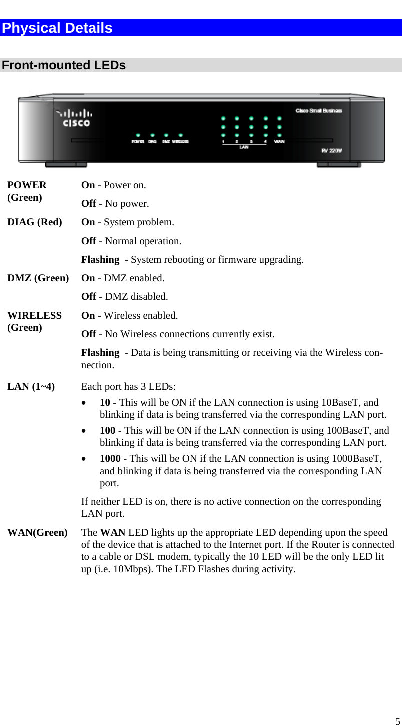
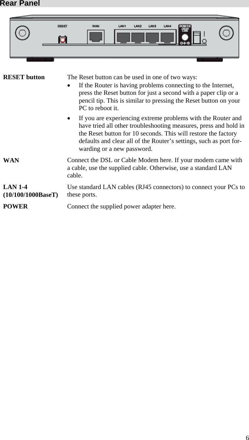
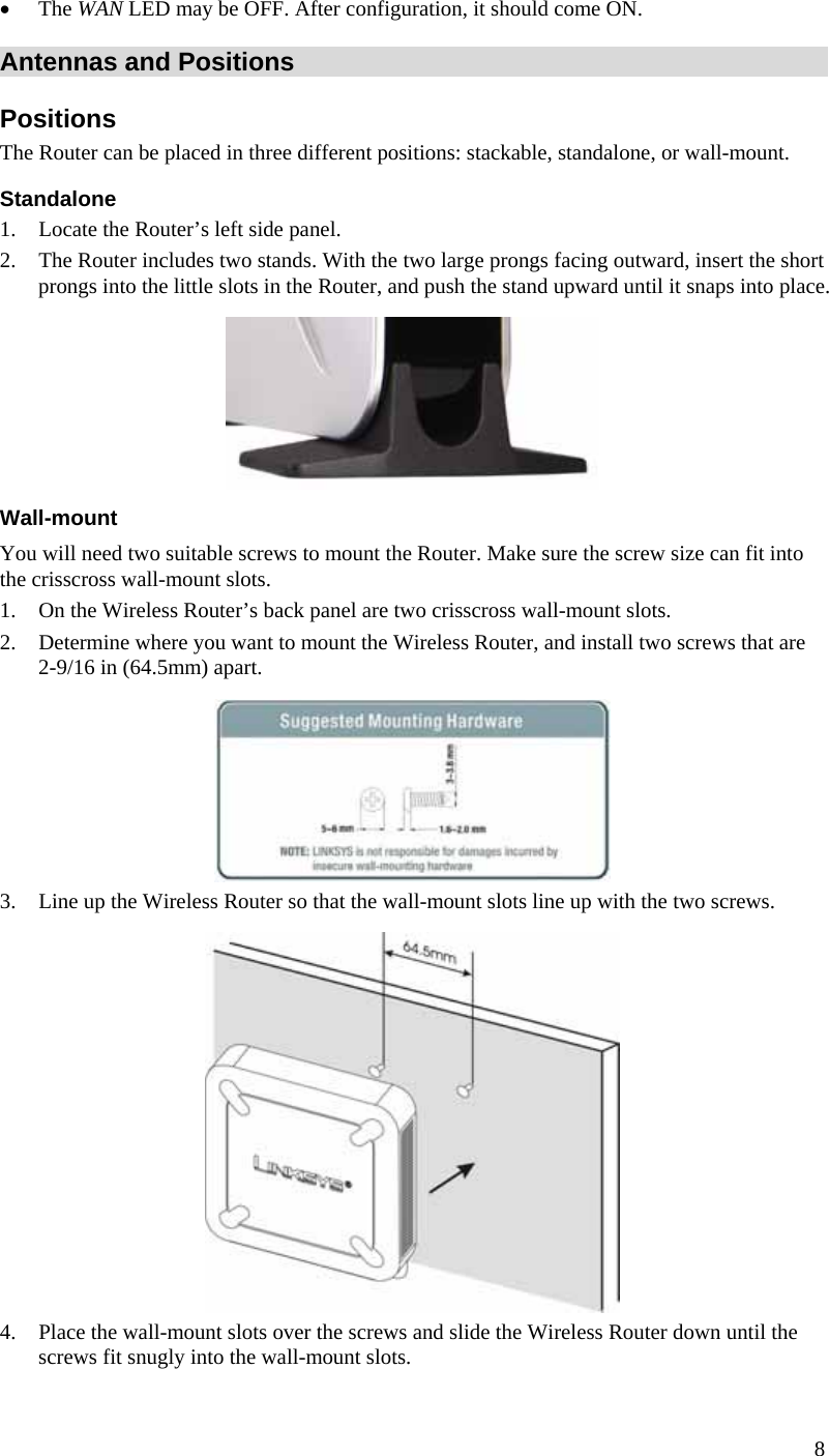
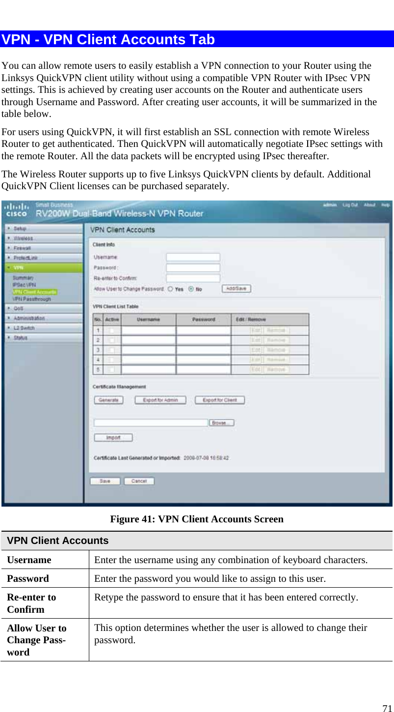
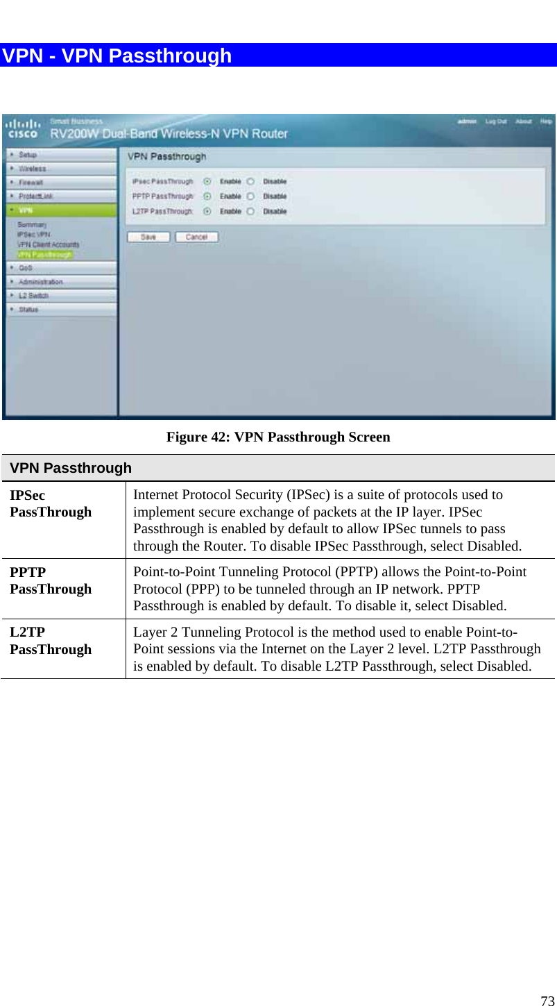
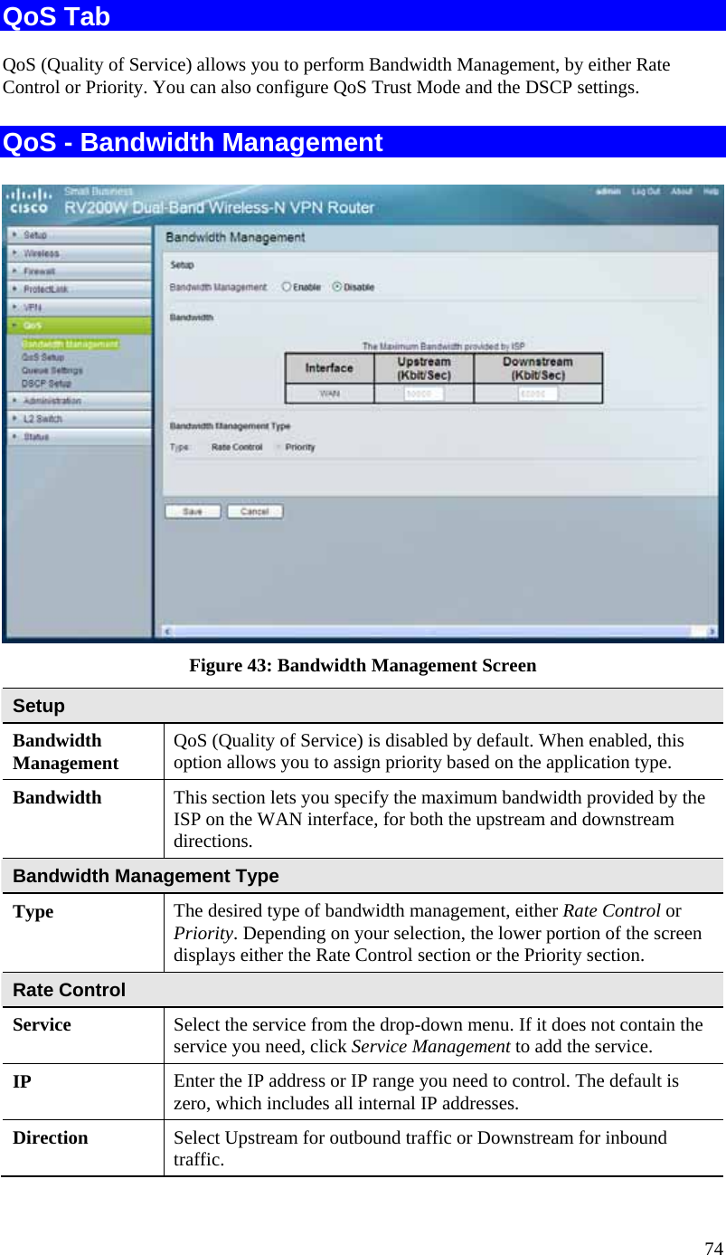
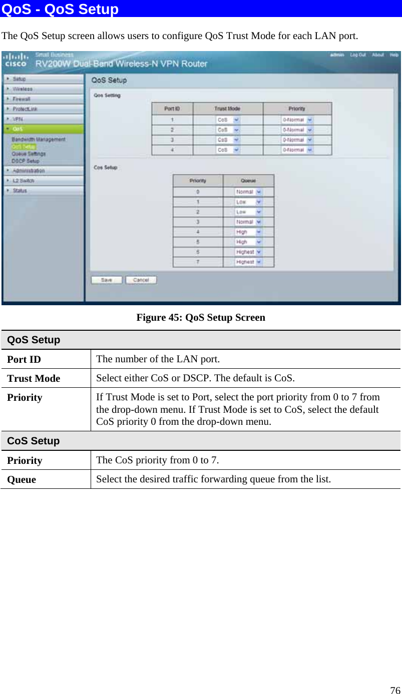
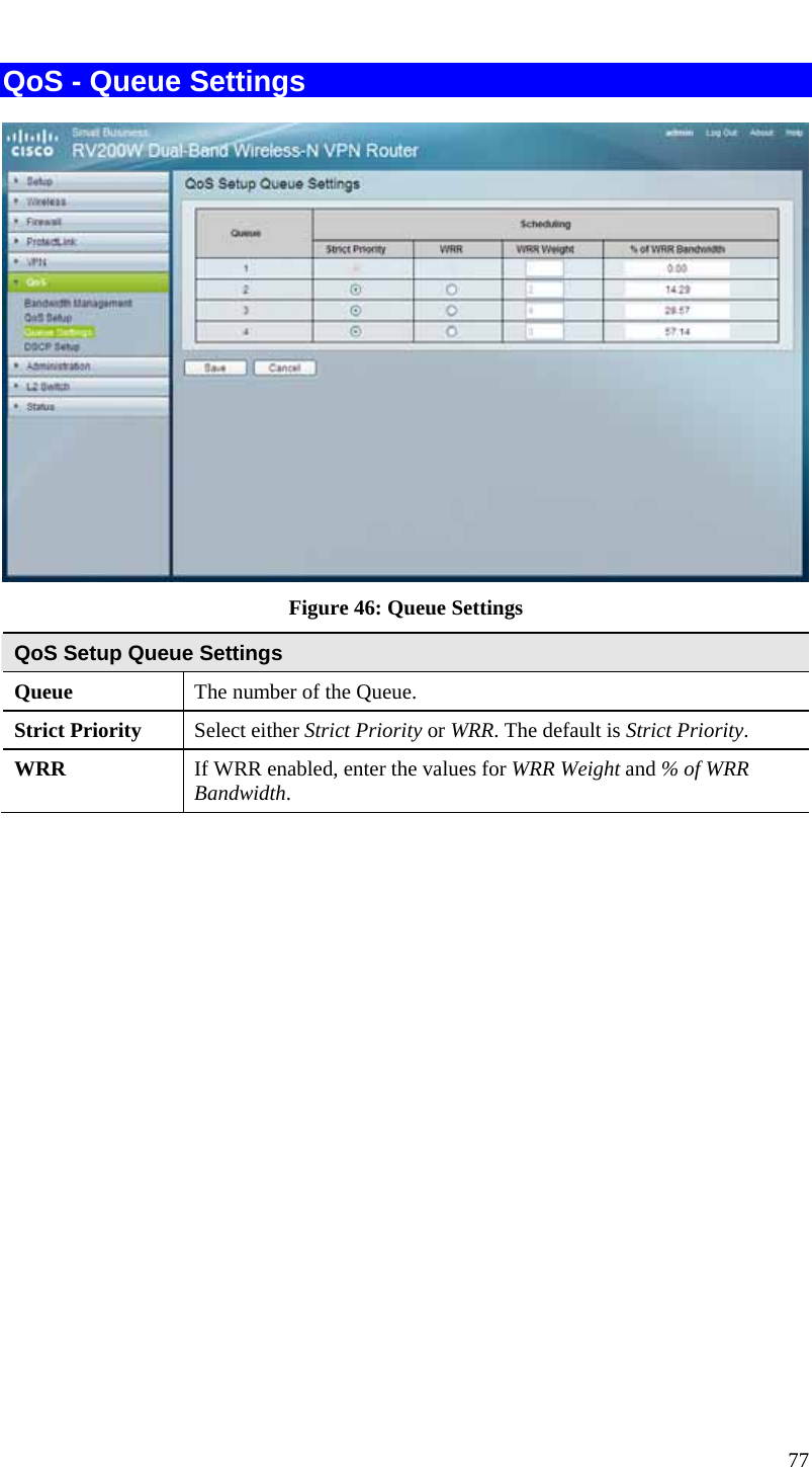
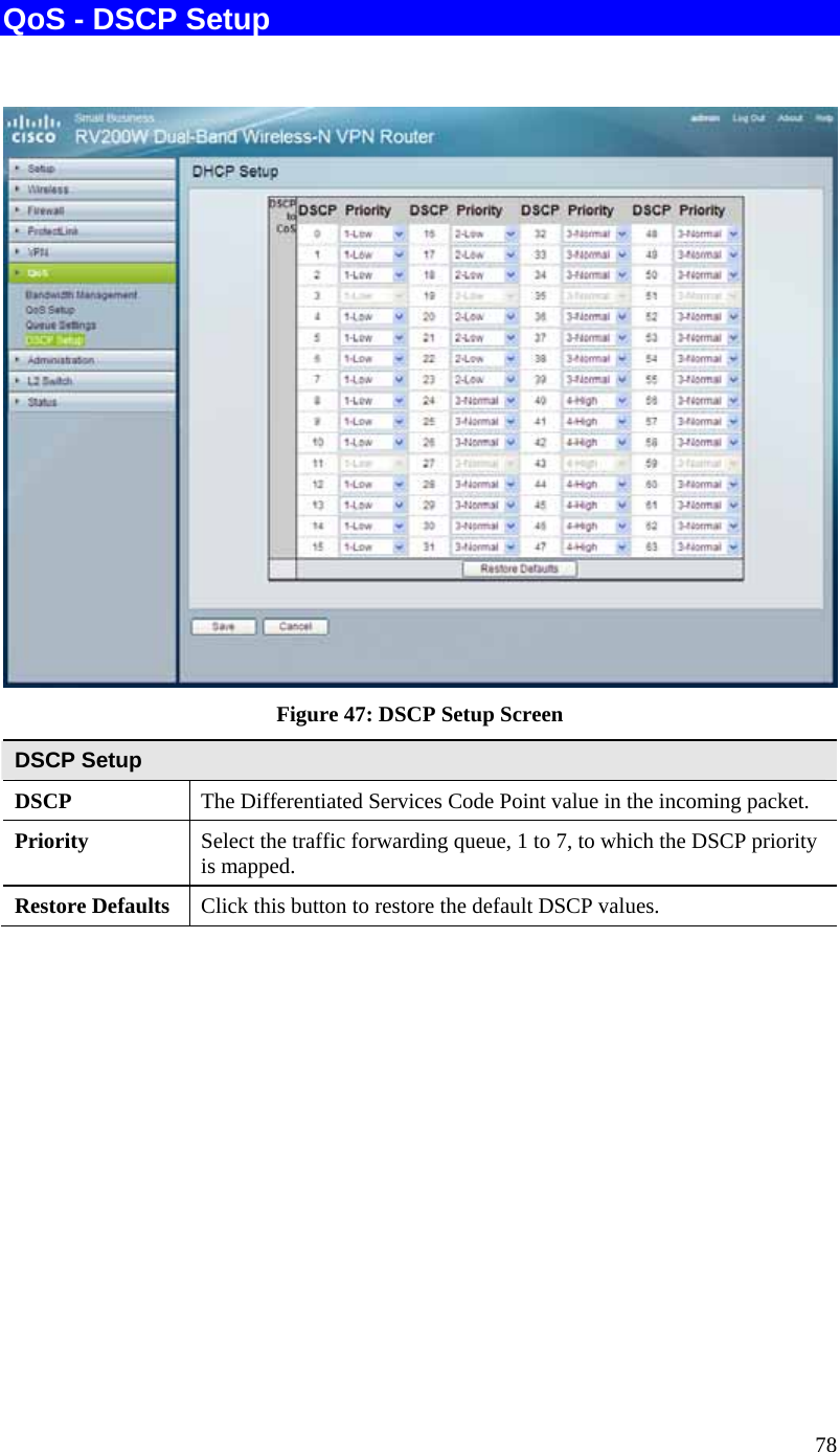
Sercomm RV220W Dual-Band Wireless VPN Router with GbE Switch User Manual
Sercomm Corporation Dual-Band Wireless VPN Router with GbE Switch
UserManual.wiki
>
Sercomm
>
RV220W User Manual
>
User manual
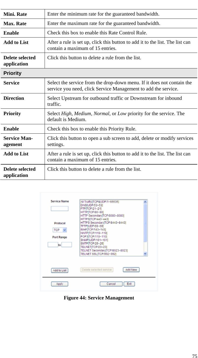
Contents
1.
User manual
2.
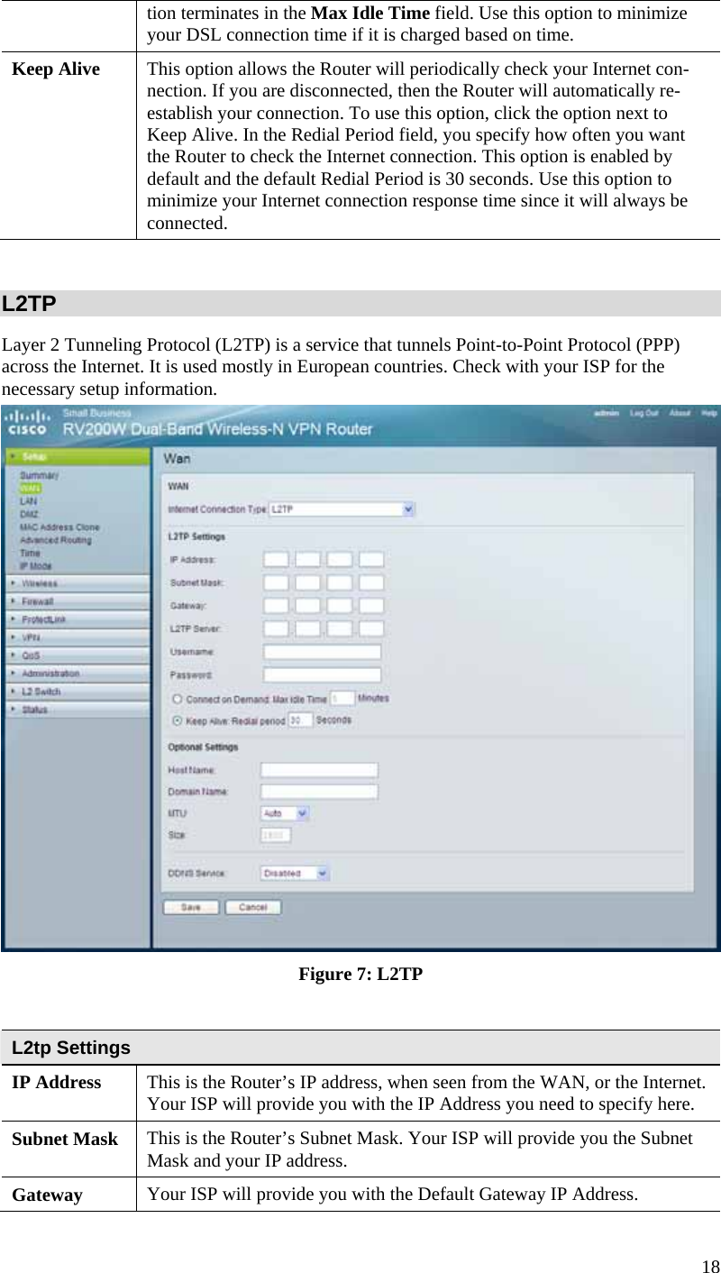
User manaul
User manual
Navigation menu
Upload a User Manual
Namespaces
Wiki Guide
HTML
PDF
Info
Views
User Manual
Discussion / Help
Navigation
![This equipment has been tested and found to comply with the limits for a Class B digital device, pursuant to part 15 of the FCC rules. These limits are designed to provide reasonable protection against harmful interference in a residential installation. This equipment generates, uses and can radiate radio frequency energy and, if not installed and used in accordance with the instructions, may cause harmful interference to radio communications. However, there is no guarantee that interference will not occur in a particular installation. If this equipment does cause harmful interference to radio or television reception, which can be determined by turning the equipment off and on, the user is encouraged to try to correct the interference by one or more of thefollowing measures: -Reorient or relocate the receiving antenna. -Increase the separation between the equipment and receiver. -Connect the equipment into an outlet on a circuit different from that to which the receiver is connected. -Consult the dealer or an experienced radio/TV technician for help. You are cautioned that changes or modifications not expressly approved by the party responsi-ble for compliance could void your authority to operate the equipment. FCC RF Radiation Exposure Statement: 1. This Transmitter must not be co-located or operating in conjunction with any other antenna or transmitter.2. This equipment complies with FCC RF radiation exposure limits set forth for an uncontrolled environment. This equipment should be installed and operated with a mini-mum distance of 20 centimeters between the radiator and your body. According to FCC 15.407(e), the device is intended to operate in the frequency band of 5.15GHz to 5.25GHz under all conditions of normal operation. Normal operation of this device is restricted to indoor used only to reduce any potential for harmful interference to co-channel MSS operations. Operation is subject to the following two conditions: (1) this device may not cause interference, and (2) this device must accept any interference, including interference that may cause unde-sired operation of the device. RSS-GEN 7.1.4: User Manual for Transmitters with Detachable Antennas The user manual of transmitter devices equipped with detachable antennas shall contain the followinginformation in a con-spicuous location: This device has been designed to operate with the antennas listed below, and having a maxi-mum gain of [2.0] dB. Antennas not included in this list or having a gain greater than [2.0] dB are strictly prohibited for use with this device. The required antenna impedance is [50] ohms. RSS-GEN 7.1.5 To reduce potential radio interference to other users, the antenna type and its gain should be so chosen that the equivalent isotropically radiated power (e.i.r.p.) is not more than that permitted for successful communication. IC RF Radiation Exposure Statement: 1. This Transmitter must not be co-located or operating in conjunction with any other antenna or transmitter.2. This equipment complies with IC RF radiation exposure limits set forth for an uncontrolled environment. This equipment should be installed and operated with a mini-mumdistance of 20 centimeters between the radiator and your body. except above RF exposure statement, for devices used at 5.15-5.25GHz should add the following wording at their user manual.According to RSS-210, the device is intended to operate in the frequency band of 5.15GHz to 5.25GHz under all conditions of normal operation. Normal operation of this device is restricted to indoor used only to reduce any potential for harmful interference to co-channel MSS operations.](https://usermanual.wiki/Sercomm/RV220W.User-manual/User-Guide-1326880-Page-7.png)