Sercomm SWDWS02N Z-Wave Door Window Sensor User Manual
Sercomm Corporation Z-Wave Door Window Sensor
Sercomm >
User Manual.pdf
SW-DWS02N Door/Window Sensor Installation Guide
Z-Wave Door/Window sensors are designed to secure the perimeter of the residential premise, and provide the
ability to add various automation services. The Z-Wave Door/Window sensor, which consists of a magnet that
attaches to a door or window, will communicate door events to the home security system. When the magnet is
moved away from the sensor, a signal will be sent to the control panel that communicates the changed state to the
security system. Signals can also be used to activate a chime or convenience lighting based on system settings.
Frequency
908
.42 /
908.40 /
916.00
M
Hz
Batter
y
Type
CR2
Battery
1 PCS
Operating Temperature 0
°
C to 50
°
C (32°F - 122°F)
Storage Temperature -20
°
C to 60
°
C (-4°F - 140°F)
Operating
Air
Range
Up to
148
feet
line of s
ight
Dimension
Device
:
67
mm x 1
9
mm x
20
mm (
2.63
" x
0.74
" x
0.
78
")
Magnet: 45 mm x 8 mm x 15 mm (1.77" x 0.31" x 0.59")
For Adding in (Inclusion) a network: Put the Z-Wave Interface Controller into “Add (Inclusion)” mode, and
following its instruction to add SW-DWS02N to your controller. This Door/Window sensor needs to be included
before installation.
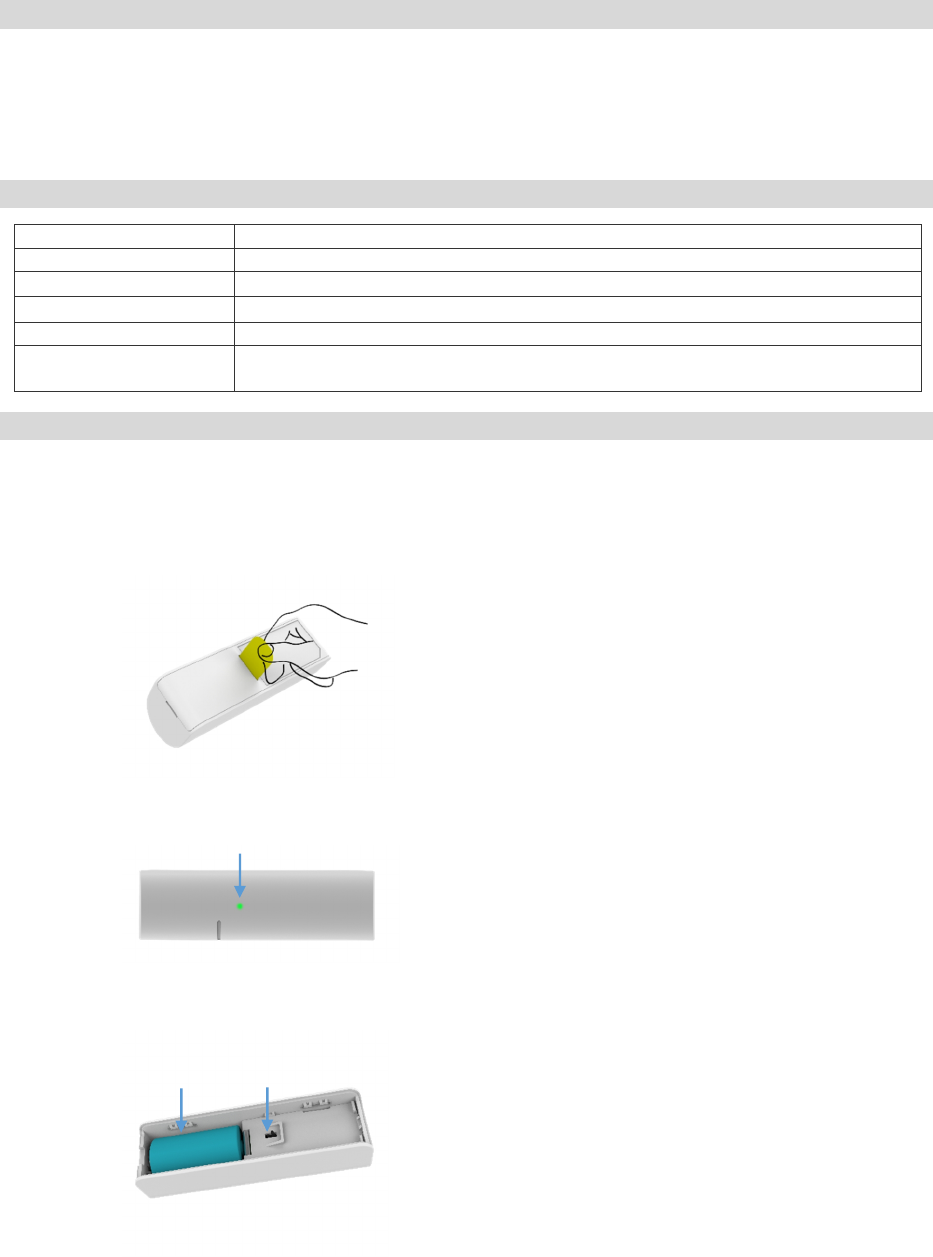
1. Pull the exposed plastic tab from the sensor. (Figure 1)
2. The Green LED indicator will be lit for one second to indicate a successful booting.
3. It will blink one time every second while scanning the network (Figure 2).
4. If network is not found after 30 seconds, the sensor will go into sleep mode. To wake the sensor again, you
need to use magnet or tamper (Figure 3) to trigger a paring process, and then sensor will repeat steps from 3 to
4.
Introduction
Specification
Add (Inclusion) Sensor
Figure 2
Figure 1
Figure 3
Green LED Indictor
CR2 Battery
T
a
mper Switch
For Removing from (Exclusion) a network: Put the Z-Wave Interface Controller into “Remove (Exclusion)” mode,
and following its instruction to delete SW-DWS02N to your Z-Wave controller.
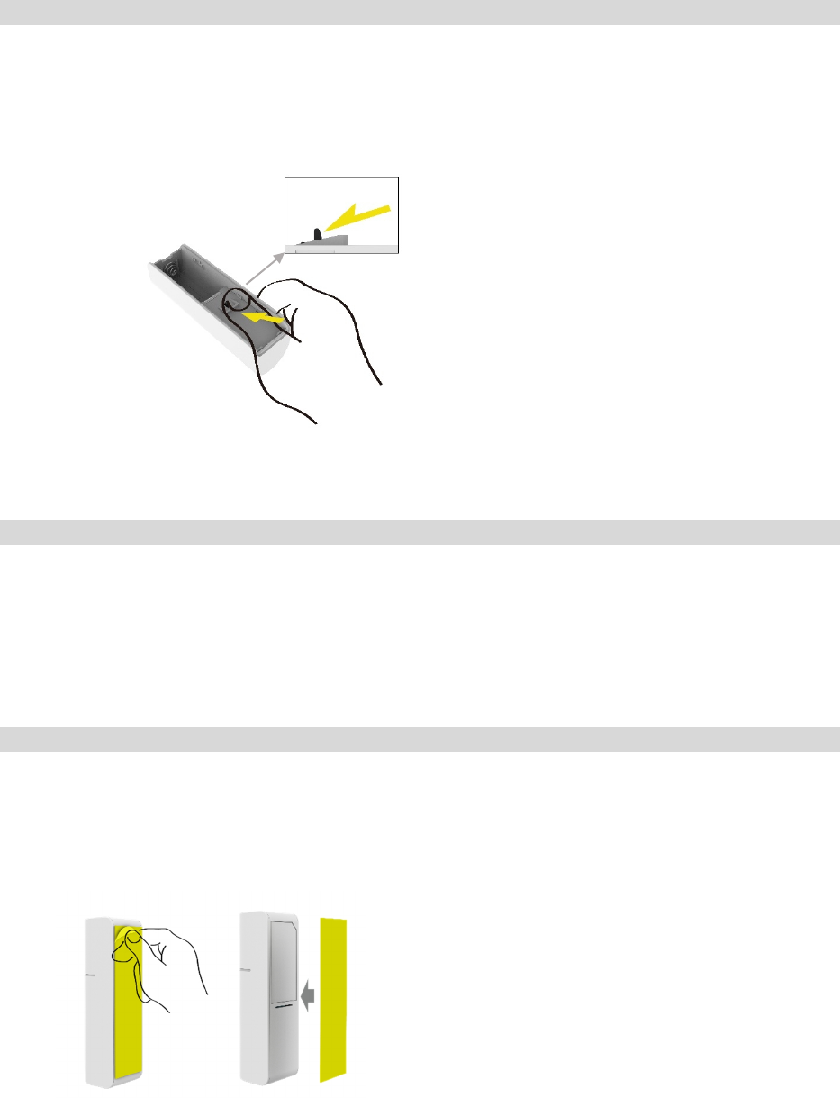
1. Remove device rear cover and pressing the tamper button three times within 2 seconds, green LED indicator
should go “On” 0.5 second and enter exclusion mode. (Figure 4).
2. If remove (exclusion) successful, go auto Adding procedure.
3. Node ID has been remove.
1. Pressing the tamper button four times within 2 seconds (Figure 4) and do not release the tamper button in the
4th pressed, and the LED will turn ON.
2. After over 3 seconds the Green LED indicator will turn OFF, then go auto Adding procedure.
3. IDs are excluded and all settings will reset to factory default.
4. Device begin auto Adding (Inclusion) mode.
Note: Use this procedure only in the event that the primary controller is lost.
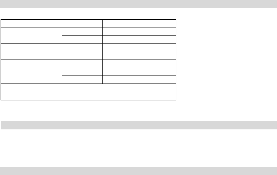
1. Please make sure that the sensor and magnet is located less than 0.7 inch from each other. For optimal
performance, it is highly recommended to install the Door/Window sensor on the fixed frame and the magnet
on the moving part of the door/window. Place the sensor near the top of the door that close to the opening
edge of the door. This is the mounting location for the sensor.
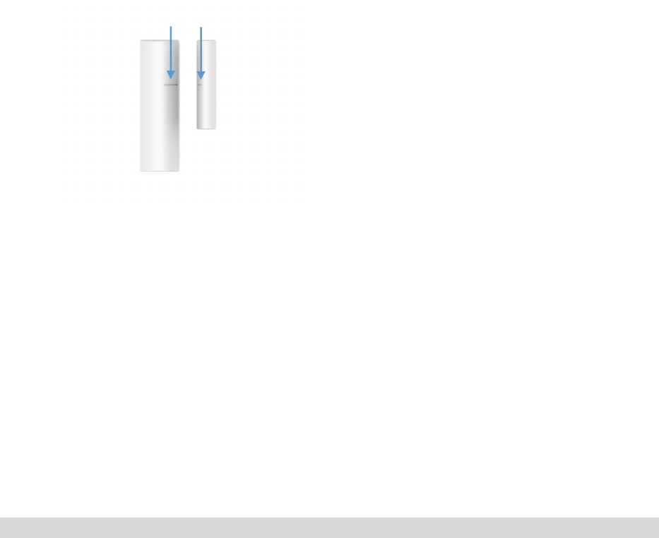
2. Use the provided double-sided tape on the sensor. Attach the sensor to the door. Press firmly and hold in place
for a few seconds (Figure 5). Secure it with silicone if needed.
3. Use provided double-sided tape on the magnet. Make sure the alignment of both sensor and magnet alignment
mark are facing each other (Figure 6). Press firmly and hold in place for a few seconds. Secure it with
silicone if needed.
Remove
(
Exclusion
)
Sensor
Inclusion
Sensor
Installation
Inclusion
Sensor
P
ress
ing
the tamper button
Figure 4
Factory
Default
Reset
Installation
Figure 5
Adhesive application surface: Acrylic, Glass
Aluminum and Stainless steel…etc.
4. SW-DWS02N can be included and operated in any Z-Wave network with other Z-Wave certified devices
from other manufacturers and/or other applications. All non-battery operated nodes within the network will
act as repeaters regardless of vendor to increase reliability of the network.
5. Association
Support grouping identifier = 1
Support one group with 5 nodes.
All triggering report and low voltage report will be sent to the associated nodes.
6. Awake mode
It will be triggering after opening bottom cover. SW-DWS02N will send “Wake Up Notification” after 10
seconds. If SW-DWS02N received “Wake Up No More Information” command then will go off or it will
wait 10 seconds then go off. It will proceed all the commands after sending the “Wake Up Notification”.
7. Auto Wake Up
Use “Wake up” command to set up the awaking time and send the wake up notification to controller.
User can use command to change the auto wake up from 1 minute to 24 hours, interval increment is 1
minute. Factory default is 120 minutes.
• COMMAND_CLASS_ZWAVEPLUS_INFO
• COMMAND_CLASS_VERSION
• COMMAND_CLASS_MANUFACTURER_SPECIFIC
• COMMAND_CLASS_DEVICE_RESET_LOCALLY
• COMMAND_CLASS_POWERLEVEL
• COMMAND_CLASS_BATTERY
• COMMAND_CLASS_NOTIFICATION
• COMMAND_CLASS_ASSOCIATION
• COMMAND_CLASS_ASSOCIATION_GRP_INFO
• COMMAND_CLASS_BASIC
• COMMAND_CLASS_WAKE_UP
• COMMAND_CLASS_FIRMWARE_UPDATE_MD
Z-Wave Command Classes
Figure 6
Alignment Mark
Switch Type Status
Notification Type Reed Switch 0x06
Tamper Switch
0x07
Event Reed Switch Close:0x17, Open:0x16
Tamper Switch
Close:0x00, Open:0x03
BASIC Report Reed Switch Close:0x00, Open:0xFF
Alarm Type Reed Switch 0x06
Tamper Switch
0x07
Alarm Level Close:0x00, Open:0xFF
1. The Green Pairing LED will stay off during the normal operation.
2. The sensor is equipped with a tamper switch. If the cover of sensor is removed, the sensor will send an alarm
to the home controller.
3. Tamper switch event will be ignored when in auto inclusion procedure.
FCC Statement: This equipment has been tested and found to comply with the limits for a Class B digital device,
pursuant to Part 15 of the FCC Rules. These limits are designed to provide reasonable protection against harmful
interference in a residential installation. This equipment generates, uses and can radiate radio frequency energy and,
if not installed and used in accordance with the instructions, may cause harmful interference to radio
communications. However, there is no guarantee that interference will not occur in a particular installation. If this
equipment does cause harmful interference to radio or television reception, which can be determined by turning the
equipment off and on, the user is encouraged to try to correct the interference by one of the following measures:
• Reorient or relocate the receiving antenna.
• Increase the separation between the equipment and receiver.
• Connect the equipment into an outlet on a circuit different from that to which the receiver is connected.
• Consult the dealer or an experienced radio/TV technician for help.
The FCC ID for this device is P27SWDWS02N
You are cautioned that changes or modifications not expressly approved by the party responsible for compliance
could void your authority to operate the equipment.
This device complies with Part 15 of the FCC Rules. Operation is subject to the following two conditions:
(1) This device may not cause harmful interference, and
(2) This device must accept any interference received, including interference that may cause undesired operation.
FCC RF Radiation Exposure Statement:
• This Transmitter must not be co-located or operating in conjunction with any other antenna or transmitter.
• This equipment complies with FCC RF radiation exposure limits set forth for an uncontrolled environment. This
equipment should be installed and operated with a minimum distance of 20 centimeters between the radiator and
your body.
Certification
Operation
Notification Type