Sercomm UB801RV3 USB Wireless-G Adapter User Manual UB801Rv3
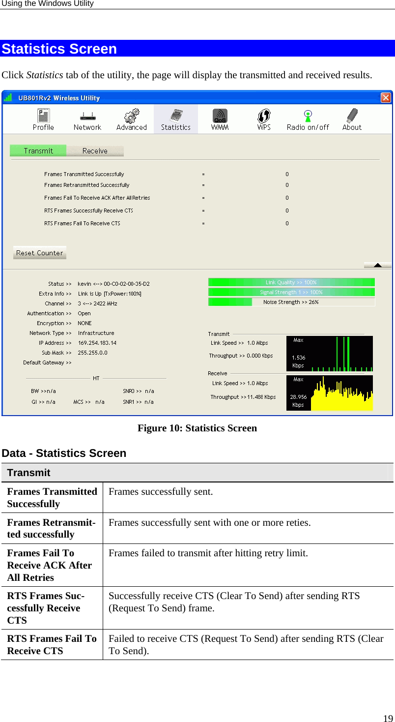
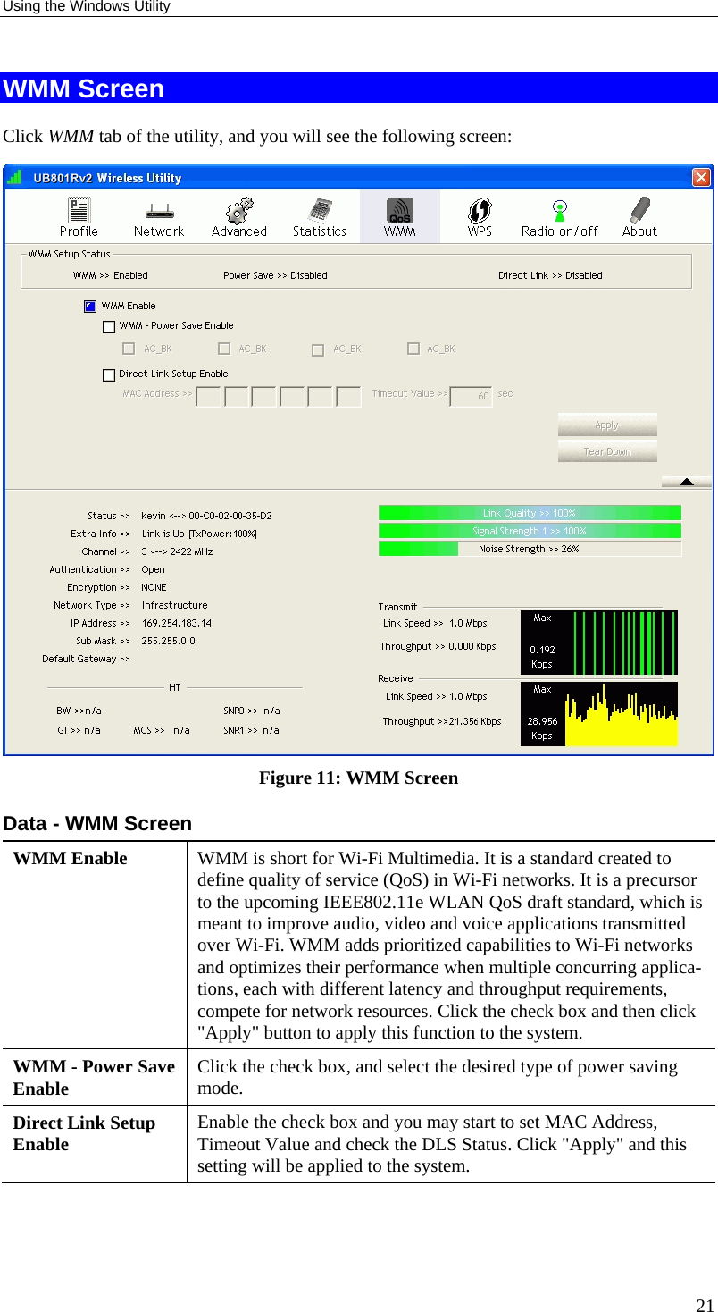
Sercomm Corporation USB Wireless-G Adapter UB801Rv3
UserManual.wiki
>
Sercomm
>
UB801RV3 User Manual
manual
Navigation menu
Upload a User Manual
Namespaces
Wiki Guide
HTML
PDF
Info
Views
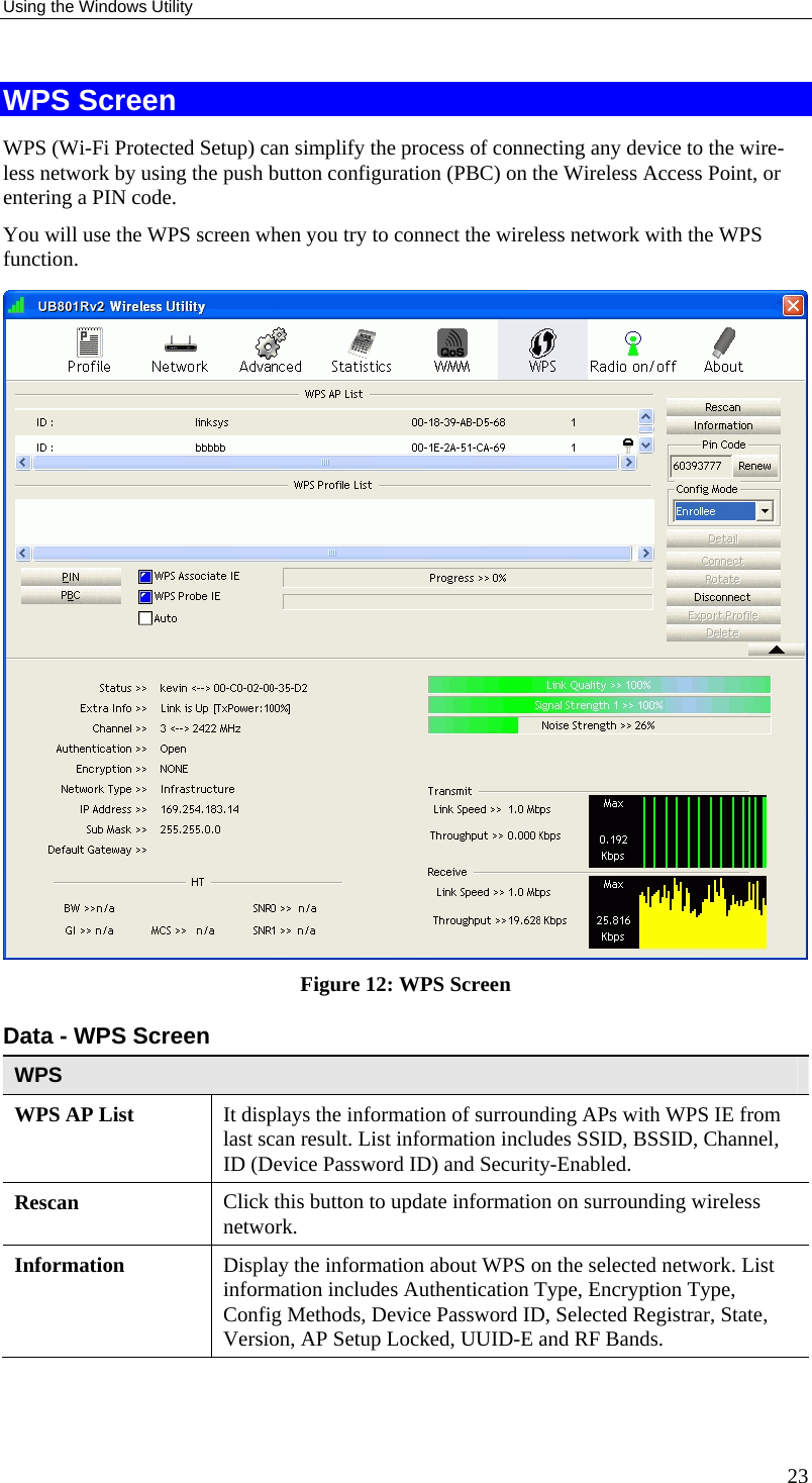
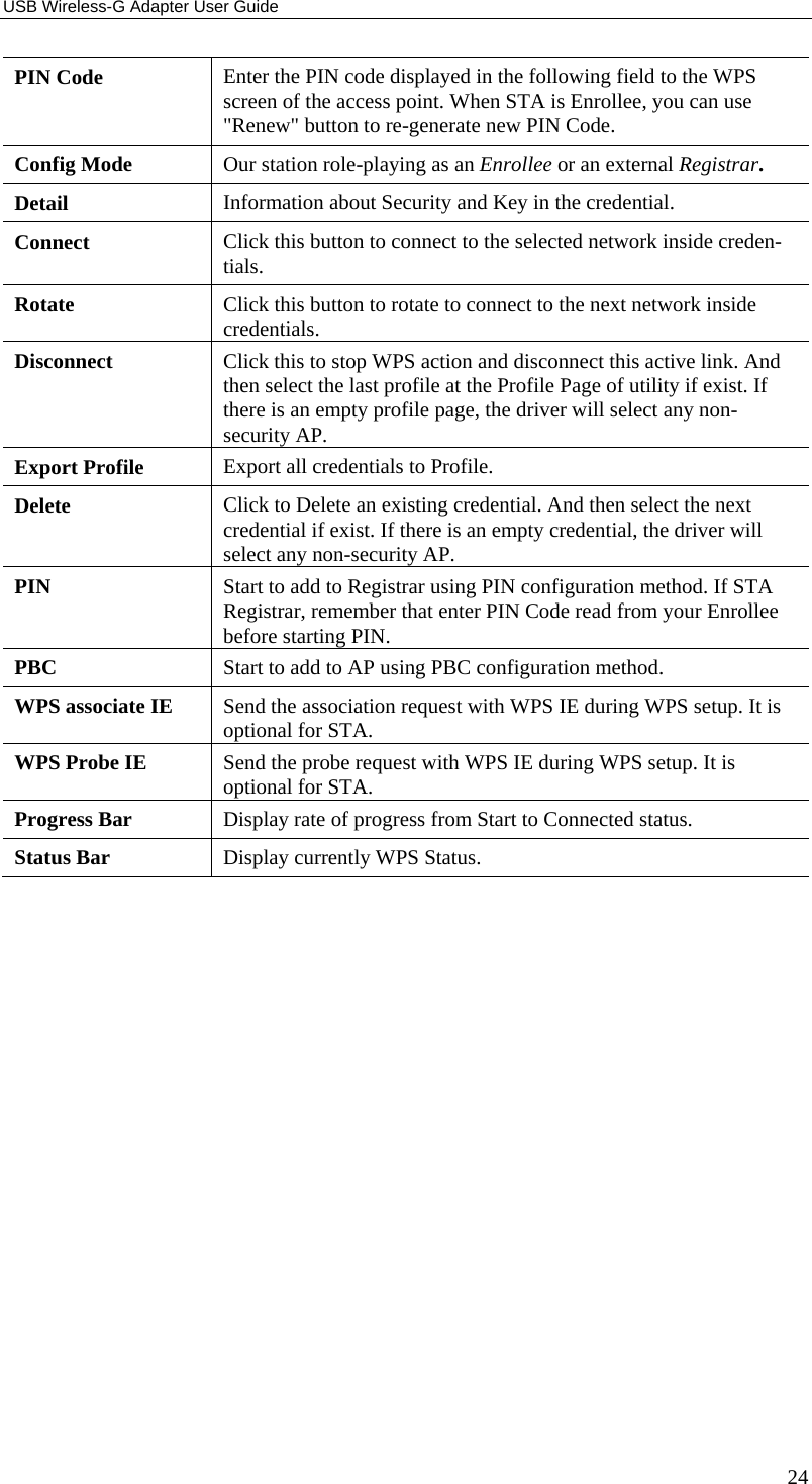
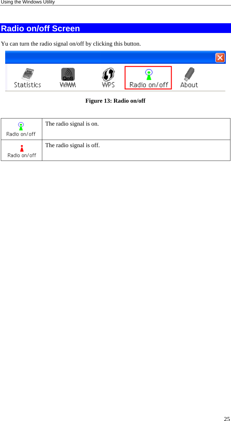
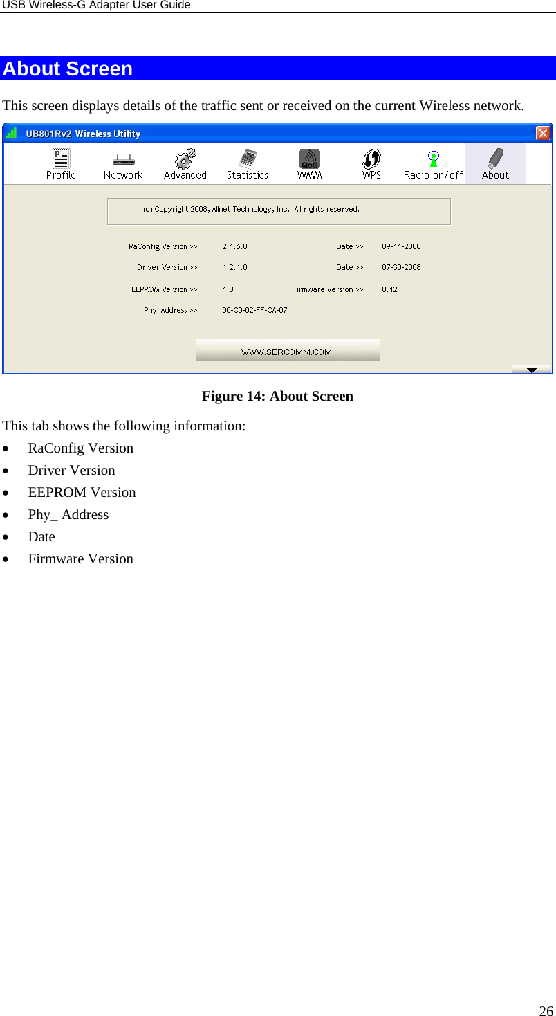
User Manual
Discussion / Help
Navigation