Sercomm UB801RV3 USB Wireless-G Adapter User Manual UB801Rv3
Sercomm Corporation USB Wireless-G Adapter UB801Rv3
Sercomm >
manual

UB801R v3
USB Wireless-G Adapter

ii
User Guide

i
Table of Contents
CHAPTER 1 INTRODUCTION ............................................................................................. 1
Package Contents .............................................................................................................. 1
Features .............................................................................................................................. 1
LEDs ................................................................................................................................... 1
Operation ........................................................................................................................... 2
CHAPTER 2 INITIAL INSTALLATION .............................................................................. 3
Requirements ..................................................................................................................... 3
Procedure ........................................................................................................................... 3
CHAPTER 3 USING THE WINDOWS UTILITY ................................................................ 7
Overview ............................................................................................................................ 7
System Tray Icon ............................................................................................................... 7
Network Screen ................................................................................................................. 8
Link Status Screen .......................................................................................................... 11
Profile Screen ................................................................................................................... 12
Advanced Screen ............................................................................................................. 17
Statistics Screen ............................................................................................................... 19
WMM Screen ................................................................................................................... 21
WPS Screen ...................................................................................................................... 23
Radio on/off Screen ......................................................................................................... 25
About Screen .................................................................................................................... 26
APPENDIX A SPECIFICATIONS ....................................................................................... 27
Wireless USB Dongle....................................................................................................... 27
APPENDIX B ABOUT WIRELESS LANS .......................................................................... 28
Modes ............................................................................................................................... 28
BSS/ESS............................................................................................................................ 28
Channels ........................................................................................................................... 29
WEP & WPA-PSK .......................................................................................................... 29
WPA2-PSK ...................................................................................................................... 29
Wireless LAN Configuration .......................................................................................... 30
P/N: 956YMJ0030
Copyright © 2008. All Rights Reserved.
Document Version: 1.0 (2008)
All trademarks and trade names are the properties of their respective owners.

1
Chapter 1
Introduction
This Chapter provides an overview of the Wireless USB Dongle's features and
capabilities.
Congratulations on the purchase of your new Wireless USB Dongle. The Wireless USB
Dongle provides a wireless network interface for your Notebook or PC.
Package Contents
The following items should be included:
• The Wireless USB Dongle Unit
• Quick Start Guide
• CD-ROM containing the on-line manual.
If any of the above items are damaged or missing, please contact your dealer immediately.
Features
• Compatible with IEEE 802.11b and 802.11g 2.4GHz
• Data transmission rate is up to 54Mbps
• Supports Turbo Mode which can enhance the data transmission rate within the specific
wireless network
• Supports WMM (Wi-Fi Multimedia) function (IEEE 802.11e QoS standard) and can meet
the requirement of the multi-media data bandwidth
• Supports 64/128-bit WEP, WPA (TKIP with IEEE802.1x) and WPA2 (AES with IEEE
802.1x) functions for high level security
• Supports CCS (Cisco Compatible Extensions) for the radio monitoring and fast roaming
• Automatic fallback which increases the data security and reliability
• Supports USB 2.0 interface
LED
Wireless USB Dongle
The Wireless USB Dongle has a single Link/Activity LED.
Link/Act LED
(Blue)
• On - Associated with the network.
• Off - Not associated with the network.
• Blinking - Data being transferred.
1

USB Wireless-G Adapter User Guide
2
Operation
You should install the supplied software on the CD-ROM before inserting the Wireless
USB Dongle.
If you have any form of the wireless utility beforehand, please uninstall it.
3
Chapter 2
Initial Installation
This Chapter covers the software installation of the Wireless USB Dongle.
Requirements
• Windows 2000/XP/Vista.
• Available USB port.
• CD-ROM drive.
• IEEE802.11b and IEEE802.11g wireless LAN.
Procedure
You should install the supplied software BEFORE inserting the Wireless USB Dongle.
1. Insert the CD-ROM into the drive on your PC.
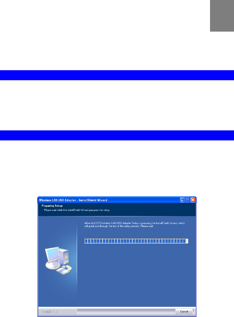
2. The installation program should start automatically. If it does not, run the Setup.exe
program.
Figure 1: Start Installation
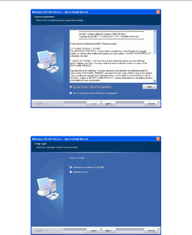
3. On the License Agreement screen, select I accept the terms of the license agreement. Click
Next.
2
USB Wireless-G Adapter User Guide
4
Figure 2: License Agreement Screen
4. Choose Install driver and Allnet WLAN Utility to install both the driver and Allnet utility
software, or Install driver only.
Figure 3: Setup Type Screen
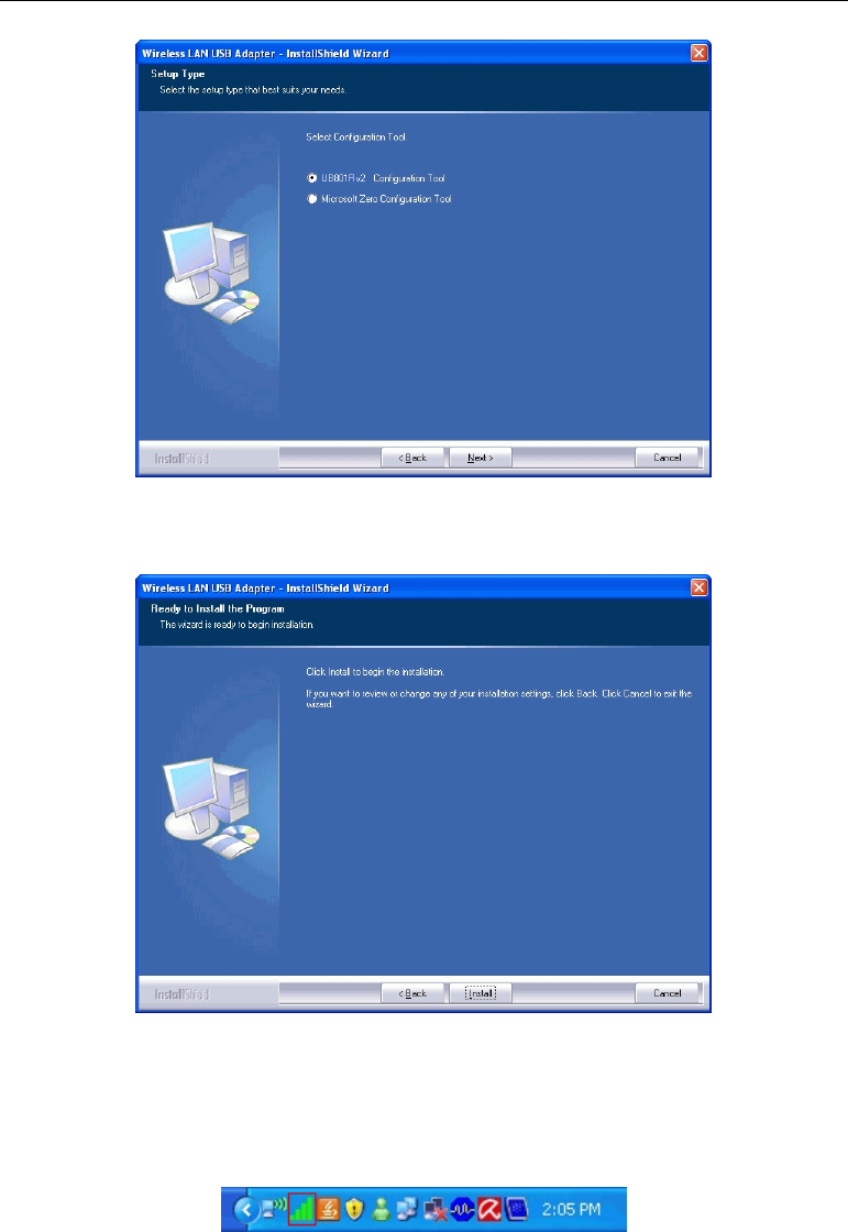
5. Select either Allnet Configuration Tool or Microsoft Zero configuration Tool on the
following screen.
Initial Installation
5
Figure 4: Windows New Hardware Screen
6. On the following screen, click Install.
7. Click Finish to exit the Wizard.
8. Insert the Wireless USB Dongle firmly into USB port of the PC.
9. If the Wireless USB Dongle was installed properly, you will now have a new icon in your
system tray, as shown below.
Figure 5: System Tray Icon

USB Wireless-G Adapter User Guide
6
Wireless USB Dongle Icon Table
Connection to the Wireless USB Dongle is established. The length of
green color indicates the signal strength.
No connection to the Wireless USB Dongle.
The Wireless USB Dongle is unplugged.
10. You can double- click this icon to configure the Wireless interface. See the following
chapter for details.
7
Chapter 3
Using the Windows Utility
This Chapter provides Setup details for the AP mode of the Wireless USB
Dongle.
Overview
If using Windows, you can use the supplied utility to configure the Wireless interface.
To Use the supplied Windows utility for Configuration
• Double-click the Wireless Utility icon in the desktop.
• Click Start - Programs - Allnet-All0233 - Wireless Utility.
This Chapter assumes you are using the supplied Wireless utility.
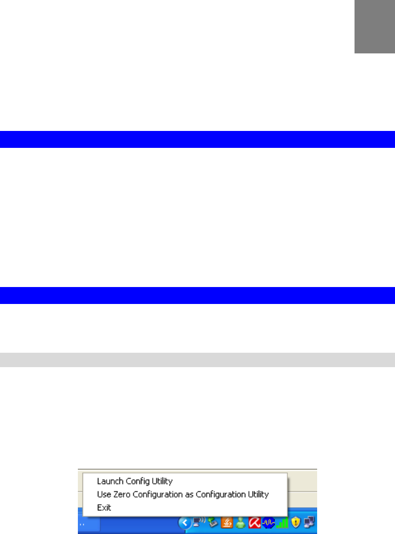
System Tray Icon
If the Wireless Utility program is running, you can double-click the icon in the System Tray or
right-click the icon and select "Launch Config Utility" to open the application.
Status Information
The menu options available from the System Tray icon are:
• Launch Config Utility - This will display the main screen of the Utility.
• Use Zero Configuration as configuration Utility - Wireless Zero Configuration (WZC),
is a service of Microsoft Windows which dynamically selects a wireless network to con-
nect.
• Exit - Terminate the connection to the Wireless USB Dongle.
Figure 6: Wireless USB Dongle menu
3
USB Wireless-G Adapter User Guide
8
Connecting to a Wireless Network
Double-click the Icon to open the Network screen, where you can select the Wireless network
you wish to join.
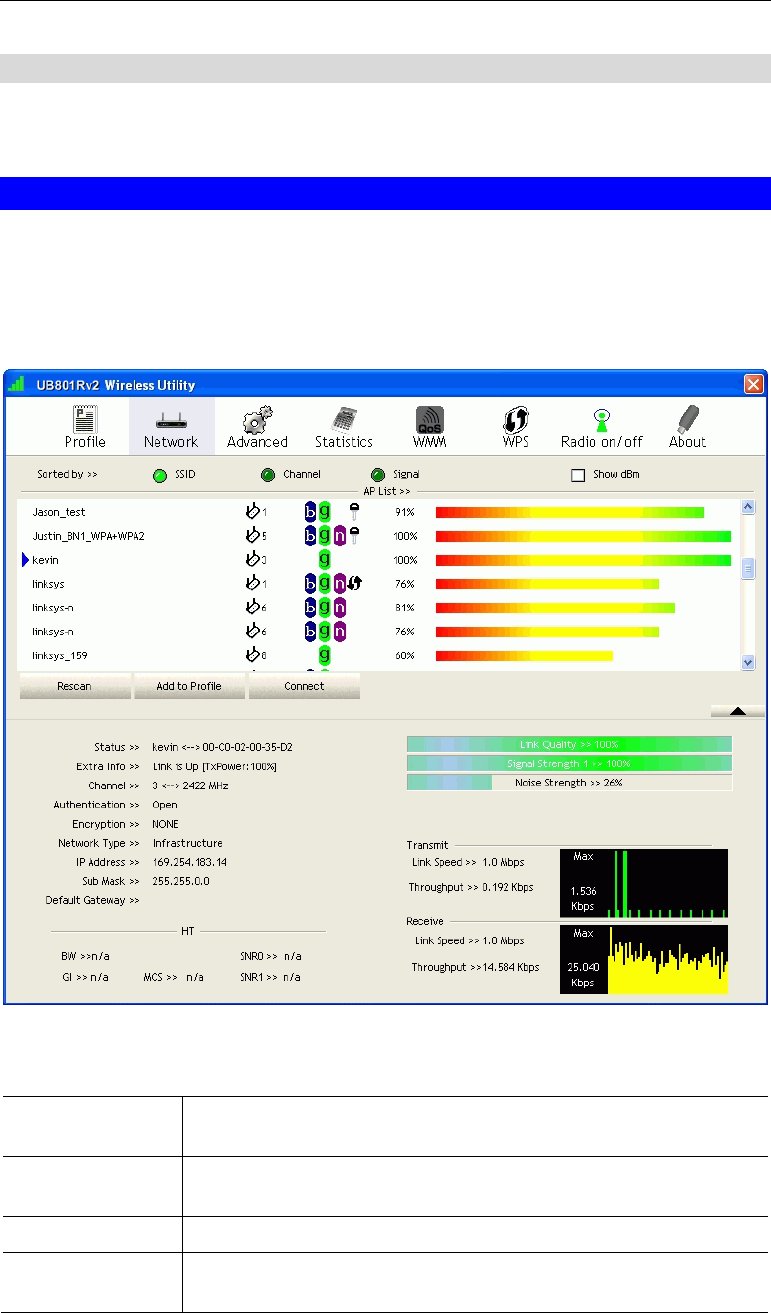
Network Screen
This screen is displayed when you double-click the system tray icon. You can also click the
Network tab in the screen.
When you open the utility program, it will scan all the channels to find all the access
points/stations within the accessible range and automatically connect to one of the wireless
devices which have the highest signal strength.
Figure 7: Network Screen
Data - Network Screen
SSID The SSID (up to 32 printable ASCII characters) is a unique name
identified in a WLAN.
Network Type It displays the Network type in use, Infrastructure for BSS, Ad-Hoc
for IBSS network.
Channel The channel used by the Wireless network.
Wireless Mode AP support wireless mode. It may support 802.11a, 802.11b or
802.11g wireless mode
Using the Windows Utility
9
Security-Enable Whether AP provides security-enabled wireless network.
Signal This is displayed as percentage (0 ~ 100%) of specified network.
Rescan Click this button to rescan for all Wireless networks.
Add to File Click this button to add the selected AP to Profile setting. It will bring
up profile page and save user's setting to a new profile.
Connect Click this button to connect the Wireless network.
Wireless Network Sequence (order)
You can click the radio buttons in the Sort by >> section (ex. SSID, Channel or Signal) to
arrange the Wireless network in the desired order.
To Connect to a Wireless Network
• Click the name of the wireless network to which you want to connect, and then click
Connect.
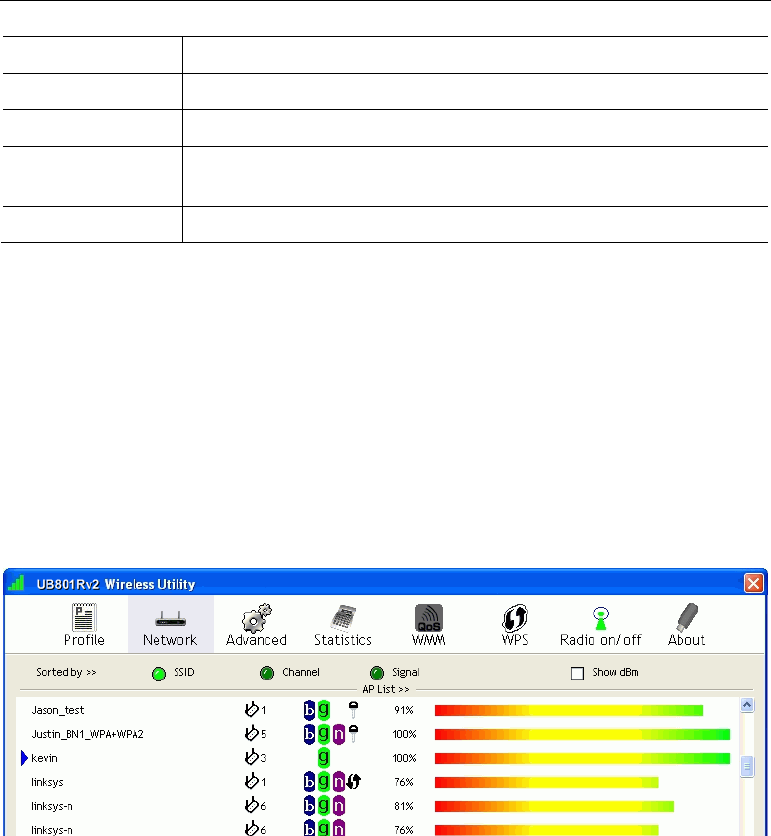
Note that once you are connected to a Wireless network, the Network screen will identify the
current wireless network with a blue arrow icon, as shown below.
Figure 8: Network Screen – Connected

USB Wireless-G Adapter User Guide
10
Icons
It indicates network type is infrastructure mode.
It indicates network type is Ad-hoc mode.
802.11b wireless mode
802.11g wireless mode
802.11n wireless mode
It indicates security-enabled wireless network.
It shows the information of Link Status Section.
It hides the information of Link Status Section.
Using the Windows Utility
11
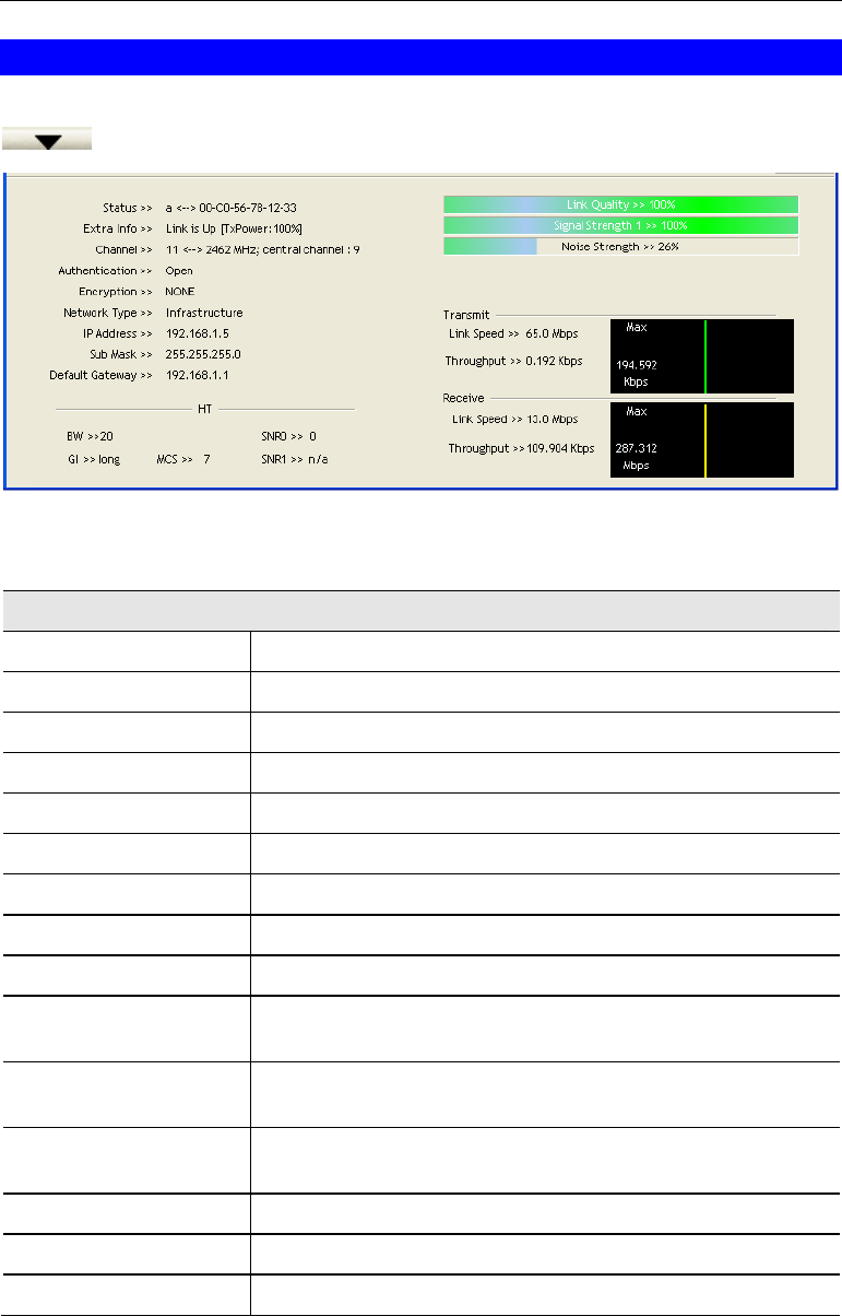
Link Status Screen
The Link Status section displays the detailed information of the current connection. Click
button to show the status screen.
Figure 10: Link Status
Data - Link Status
Link Information
Status It will indicate the current link status.
Extra Info It shows the link status.
Channel It displays the current channel in use.
Authentication It will indicate the current authentication mode in use.
Encryption It shows the wireless security that the wireless network is using.
Network Type This will indicate "Infrastructure" or "Ad-hoc".
IP Address It shows the current IP address on the wireless interface.
Subnet Mask Subnet mask for the current IP address.
Default Gateway Gateway IP address associated with the current IP address.
HT It displays current HT status in use (802.11n wireless card
only).
Link Quality It displays connection quality based on signal strength and
TX/RX packet error rate.
Signal Strength (1~3) It receives signal strength (1~3), user can choose to display as
percentage or dBm format.
Noise Strength It displays noise signal strength.
Link Speed It will show current transmit rate and receive rate.
Throughout It displays transmits and receive throughput in unit of Mbps.
USB Wireless-G Adapter User Guide
12
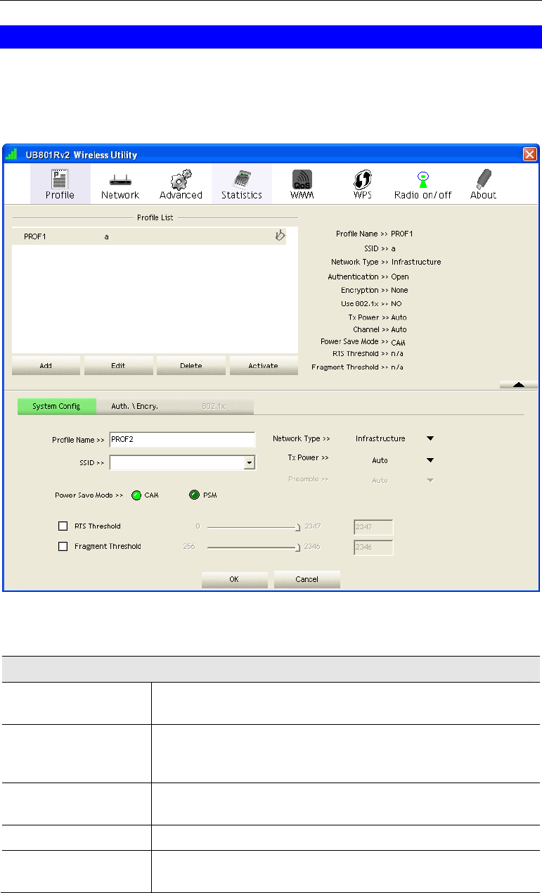
Profile Screen
Click Add to Profile button on the Network tab, or you can choose Profile tab of the utility,
then click Add, the Add Profile window will pop up. Users can setup the general settings,
encryption and authentication settings and so on. If you want to do the general settings, please
follow the instructions below.
Figure 10: Profile Screen
Data - Profile Screen
System Config
Profile Name Enter or select a suitable name for this profile. Each profile must
have a unique name.
SSID If the desired wireless network is currently available, you can
select its SSID. Otherwise, type in the SSID of the desired wire-
less network.
Power Save Mode Select either CAM (Constantly Awake Mode) or PSM (Power
Saving Mode).
RTS Threshold Select a value within the range of 0 to 2347 bytes
Fragment Threshold Select the value from 256 to 2346 bytes. The default value is
2346.

Using the Windows Utility
13
Network Type Select the desired option:
• Infrastructure - Select this to connect to an Access point.
• Ad-Hoc - Select this if you are connecting directly to another
computer.
Tx Power Select the Tx (transmission) power according to the real envi-
ronment.
Preamble The preamble defines the length of the CRC (cyclic redundancy
check). Select either Auto or Long Preamble.
OK button Click this button to save the settings and close the page.
Cancel button The "Cancel" button will discard any data you have entered and
exit the page.
Auth./Encyp.
Authentication You MUST select the option to match the Wireless LAN you
wish to join. The available options are:
• Open - Broadcast signals are not encrypted. This method can
be used only with no encryption or with WEP.
• Shared - Broadcast signals are encrypted using WEP. This
method can only be used with WEP.
• LEAP - Light Extensible Authentication Protocol is a pre-
EAP, Cisco-proprietary protocol. If selected, you have to en-
ter the identity, password and domain name of your
computer.
• WPA - This version of WPA requires a Radius Server on
your LAN to provide the client authentication according to
the 802.1x standard. Data transmissions are encrypted using
the WPA standard.
• WPA-PSK - PSK means "Pre-shared Key". You must enter
this Passphrase value; it is used for both authentication and
encryption.
• WPA2 - This version of WPA2 requires a Radius Server on
your LAN to provide the client authentication according to
the 802.1x standard. Data transmissions are encrypted using
the WPA2 standard.
• WPA2-PSK - This is a further development of WPA-PSK,
and offers even greater security. You must enter this Pass-
phrase value; it is used for both authentication and
encryption.
• WPA None - If selected, you can only set encryption and
WPA-Preshared Key settings.

USB Wireless-G Adapter User Guide
14
Encryption The available options depend on the Authentication method
selected above. The possible options are:
• None - No data encryption is used.
• WEP - If selected, you must enter the WEP data shown
below. This WEP data must match the Access Point or other
Wireless stations.
• AES, TKIP - These options are available with WPA-PSK,
WPA2-PSK, WPA and WPA2. Select the correct option.
Use 802.1x This setting only takes effect when using Open, Shared, WPA or
WPA2 mode. If enabled, click the 802.1x tab to configure the
related settings.
WPA Preshared Key For WPA-PSK and WPA2-PSK modes, you need to enter the
desired value (8~63 characters). Data is encrypted using a 256Bit
key derived from this key. Other Wireless Stations must use the
same key.
WEP Key (1~4) This setting is only available for Open or Shared mode.
There are 2 modes:
• Hex - Only "A~F", "a~f", and "0~9" are allowed to be
entered.
• ASCII - Numerical values, characters or signs are all al-
lowed to be entered.

Using the Windows Utility
15
802.1x
EAP Method There are 5 methods in the drop-down list.
• PEAP - Protect Extensible Authentication Protocol. PEAP
transport securely authentication data by using tunneling be-
tween PEAP clients and an authentication server. PEAP can
authenticate wireless LAN clients using only server-side cer-
tificates, thus simplifying the implementation and
administration of a secure wireless LAN.
• TLS-Smart Card - Transport Layer Security. Provides for
certificate-based and mutual authentication of the client and
the network. It relies on client-side and server-side certifi-
cates to perform authentication and can be used to
dynamically generate user-based and session-based WEP
keys to secure subsequent communications between the
WLAN client and the access point.
• TTLS - Tunneled Transport Layer Security. This security
method provides for certificate-based, mutual authentication
of the client and network through an encrypted channel. Un-
like EAP-TLS, EAP-TTLS requires only server-side
certificates.
• EAP-FAST - Flexible Authentication via Secure Tunneling.
It was developed by Cisco. Instead of using a certificate, mu-
tual authentication is achieved by means of a PAC (Protected
Access Credential) which can be managed dynamically by
the authentication server. The PAC can be provisioned (dis-
tributed one time) to the client either manually or
automatically. Manual provisioning is delivery to the client
via disk or a secured network distribution method. Automatic
provisioning is an in-band, over the air, distribution.
• MD5-Challenge - Message Digest Challenge. Challenge is
an EAP authentication type that provides base-level EAP
support. It provides for only one-way authentication - there is
no mutual authentication of wireless client and the network.
Tunnel Authentica-
tion Select the desired option from the drop-down list.
Session Resumption After reconnecting the signal which broke up, you can enable the
session resumption to reduce the transferring packet to accelerate
the speed.
Authentication ID /
Password Enter the required data into the fields.
Tunnel ID / Password Enter the ID and Password for the tunnel.
Use Client certificate Click the checkbox to enable certificate authority server function.
Use certificate chain When the EAP authentication type such as TLS, TTLS or PEAP
is selected and required a certification to tell the client what
server credentials to accept from the authentication server in
order to verify the server, you have to enable this function and
enter the required data in the related fields.

USB Wireless-G Adapter User Guide
16
To add a profile
1. On the Profile tab, click Add button.
2. Complete and verify the settings on this screen are correct.
3. Click OK.
To delete a profile
1. On the Profile tab, select the profile that you want to delete.
2. Click Delete.
To edit a profile
1. On the Profile tab, select the profile that you want to edit.
2. Click Edit button.
3. Change the profile settings as necessary.
4. Click OK.
To enable a profile
1. In the list of available profiles, click the profile that you want to enable.
2. Click Activate.
Using the Windows Utility
17
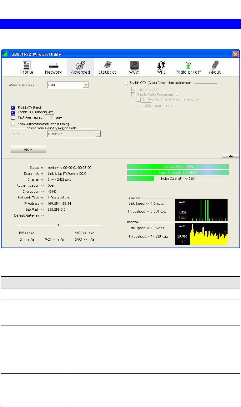
Advanced Screen
Click Advanced tab of the utility, you can configure the detailed settings in this page.
Figure 9: Advanced Screen
Data - Advanced Screen
Advanced
Wireless Mode Select the desired wireless mode.
Enable Tx Burst Tx Burst enables the adapter to deliver better throughput during a
period of time but the function only takes effect when connecting
with the AP which also supports Tx Burst.
Enable TCP
Window Size The TCP Window is the amount of data which a sender can send
on a particular connection before it gets an acknowledgement back
from the receiver that it has gotten some of it. When the router or
AP which the adapter is connecting to has set up the TCP Window,
you can enable the parameter to meet the data size for the router or
AP connection. The larger TCP Window the better performance.
Fast Roaming at.. When you want to fast roaming to the network nearby without
intercepting the wireless connection especially the adapter is
applied to the multimedia application or a voice call, you can
enable this function.

USB Wireless-G Adapter User Guide
18
Show Authentica-
tion Status Dialog When connecting to an AP with authentication, if enabling this
function, it will display dialogs about 802.1x authentication during
the process.
Select Your Coun-
try Region Code There are 8 kinds of Country Region Codes to choose from.
Enable CCX (Cisco
Compatible
eXtensions)
CCX (Cisco Compatible Extensions) is developed by Cisco for the
radio monitoring and fast roaming.
• Turn on CCKM: During normal operation, LEAP-enabled
client devices mutually authenticate with a new access point by
performing a complete LEAP authentication, including com-
munication with the main RADIUS server. When you
configure your wireless LAN for fast re-association, however,
LEAP-enabled client devices roam from one access point to
another without involving the main server. Using Cisco Cen-
tralized Key Management (CCKM), an access point configured
to provide Wireless Domain Services (WDS) takes the place of
the RADIUS server and authenticates the client so quickly that
there is no perceptible delay in voice or other time-sensitive
applications.
• Enable Radio Measurement: When this parameter is enabled,
the Cisco AP can run the radio monitoring through the asso-
ciated CCX-compliant clients to continuously monitor the
WLAN radio environment and discover any new Aps that are
transmitting beacons.
Apply Click this button to save the changes you made.
Using the Windows Utility
19
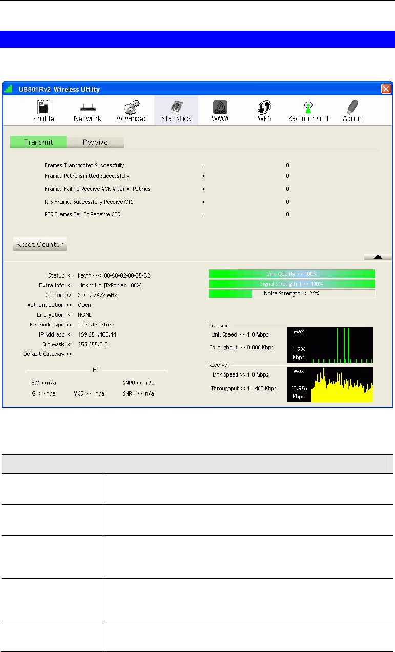
Statistics Screen
Click Statistics tab of the utility, the page will display the transmitted and received results.
Figure 10: Statistics Screen
Data - Statistics Screen
Transmit
Frames Transmitted
Successfully Frames successfully sent.
Frames Retransmit-
ted successfully Frames successfully sent with one or more reties.
Frames Fail To
Receive ACK After
All Retries
Frames failed to transmit after hitting retry limit.
RTS Frames Suc-
cessfully Receive
CTS
Successfully receive CTS (Clear To Send) after sending RTS
(Request To Send) frame.
RTS Frames Fail To
Receive CTS Failed to receive CTS (Request To Send) after sending RTS (Clear
To Send).

USB Wireless-G Adapter User Guide
20
Receive
Frames Receive
Successfully Frames received successfully.
Frames Receive
With CRC Error Frames received with CRC error.
Frames Dropped
Due To Out-of-
Resource
Frames dropped due to resource problem.
Duplicate Frames
Received Frames received more than twice.
Reset Counter Click the button to reset counters to zero.
Using the Windows Utility
21
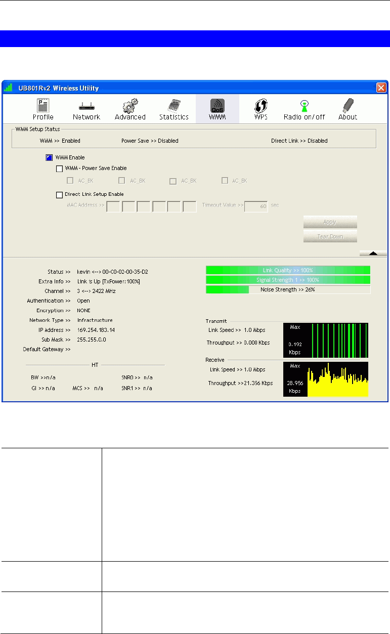
WMM Screen
Click WMM tab of the utility, and you will see the following screen:
Figure 11: WMM Screen
Data - WMM Screen
WMM Enable WMM is short for Wi-Fi Multimedia. It is a standard created to
define quality of service (QoS) in Wi-Fi networks. It is a precursor
to the upcoming IEEE802.11e WLAN QoS draft standard, which is
meant to improve audio, video and voice applications transmitted
over Wi-Fi. WMM adds prioritized capabilities to Wi-Fi networks
and optimizes their performance when multiple concurring applica-
tions, each with different latency and throughput requirements,
compete for network resources. Click the check box and then click
"Apply" button to apply this function to the system.
WMM - Power Save
Enable Click the check box, and select the desired type of power saving
mode.
Direct Link Setup
Enable Enable the check box and you may start to set MAC Address,
Timeout Value and check the DLS Status. Click "Apply" and this
setting will be applied to the system.

USB Wireless-G Adapter User Guide
22
MAC Address Enter the remote system which you want to connect with. When
you want to enable this function, you have to make sure that your
wireless network supports WMM function and then enter the MAC
address of the adapter which wants to connect with the remote
system.
Timeout Value The utility performs time-outs so that the program does not sit idle
waiting for input that may never come. Set a value to apply to the
system with WMM.
Apply Click this button to save the changes you made.
Tear Down Click this button will disconnect the selected Direct Link Setup.
Using the Windows Utility
23
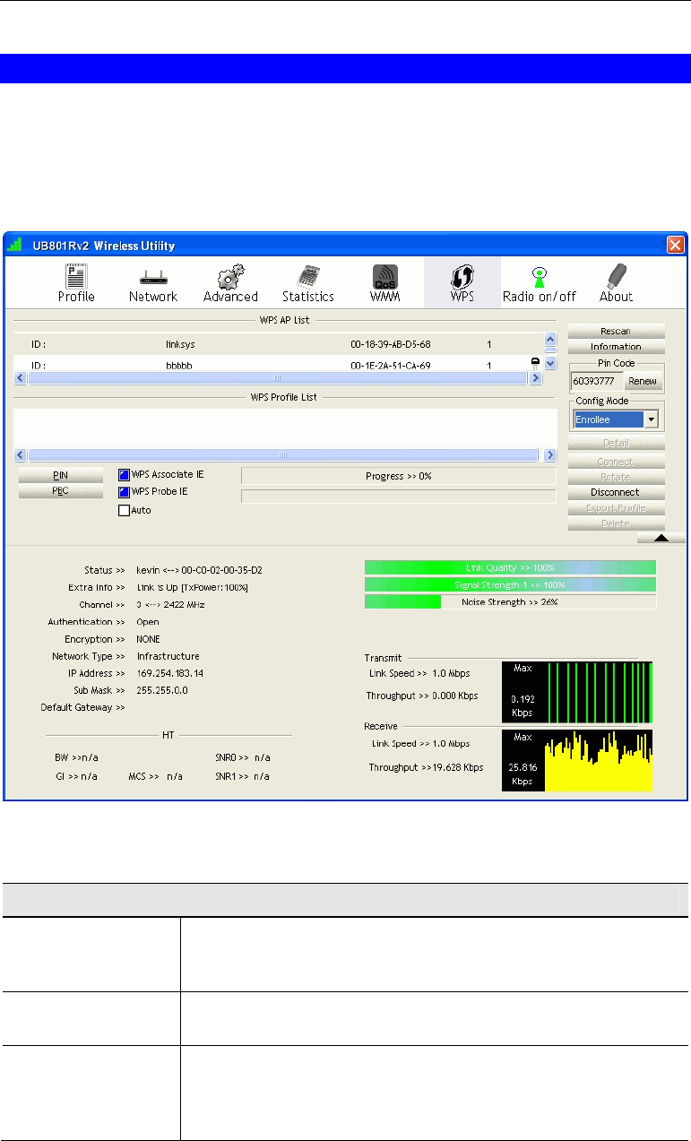
WPS Screen
WPS (Wi-Fi Protected Setup) can simplify the process of connecting any device to the wire-
less network by using the push button configuration (PBC) on the Wireless Access Point, or
entering a PIN code.
You will use the WPS screen when you try to connect the wireless network with the WPS
function.
Figure 12: WPS Screen
Data - WPS Screen
WPS
WPS AP List It displays the information of surrounding APs with WPS IE from
last scan result. List information includes SSID, BSSID, Channel,
ID (Device Password ID) and Security-Enabled.
Rescan Click this button to update information on surrounding wireless
network.
Information Display the information about WPS on the selected network. List
information includes Authentication Type, Encryption Type,
Config Methods, Device Password ID, Selected Registrar, State,
Version, AP Setup Locked, UUID-E and RF Bands.

USB Wireless-G Adapter User Guide
24
PIN Code Enter the PIN code displayed in the following field to the WPS
screen of the access point. When STA is Enrollee, you can use
"Renew" button to re-generate new PIN Code.
Config Mode Our station role-playing as an Enrollee or an external Registrar.
Detail Information about Security and Key in the credential.
Connect Click this button to connect to the selected network inside creden-
tials.
Rotate Click this button to rotate to connect to the next network inside
credentials.
Disconnect Click this to stop WPS action and disconnect this active link. And
then select the last profile at the Profile Page of utility if exist. If
there is an empty profile page, the driver will select any non-
security AP.
Export Profile Export all credentials to Profile.
Delete Click to Delete an existing credential. And then select the next
credential if exist. If there is an empty credential, the driver will
select any non-security AP.
PIN Start to add to Registrar using PIN configuration method. If STA
Registrar, remember that enter PIN Code read from your Enrollee
before starting PIN.
PBC Start to add to AP using PBC configuration method.
WPS associate IE Send the association request with WPS IE during WPS setup. It is
optional for STA.
WPS Probe IE Send the probe request with WPS IE during WPS setup. It is
optional for STA.
Progress Bar Display rate of progress from Start to Connected status.
Status Bar Display currently WPS Status.
Using the Windows Utility
25
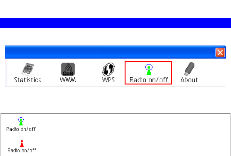
Radio on/off Screen
Yu can turn the radio signal on/off by clicking this button.
Figure 13: Radio on/off
The radio signal is on.
The radio signal is off.
USB Wireless-G Adapter User Guide
26
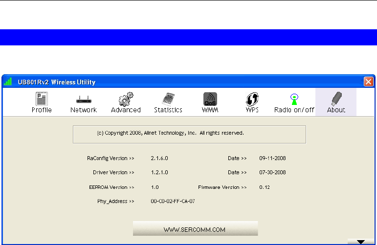
About Screen
This screen displays details of the traffic sent or received on the current Wireless network.
Figure 14: About Screen
This tab shows the following information:
• RaConfig Version
• Driver Version
• EEPROM Version
• Phy_ Address
• Date
• Firmware Version

27
Appendix A
Specifications
Wireless USB Dongle
Model: UB801Rv3
Standards: IEEE 802.11b, IEEE 802.11g
Computer Slot Type: USB
Chipset: Ralink RT2070(MAC/BB/RF)
Tx: 1
Rx: 1
Date Rates: 54, 48, 36, 24, 18, 12, 9, and 6 Mbps (802.11g)
11, 5.5, 2, 1 Mbps (802.11b)
Operating Channels: 11 for North America, 13 for Europe and Japan
Operating Frequency: 2.4 ~ 2.4835 GHz
Modulation Technique:
802.11g: OFDM
802.11b: CCK,QPSK,BPSK
Media Access Protocol: CSMA/CA
Operating Voltage: 5V +/- 5%
Transmit Power: 802.11g: 13.5 +/- 1 dBm
802.11b: 17 +/- 1 dBm
Security: WPA/WPA2; 128-bit TKIP/AES encryption, 40/64-, 128-bit
WEP shared-key encryption
802.1x, and EAP-TLS, and PEAP authentication
OS Requirements: Windows Vista/XP/2000
A
28
Appendix B
About Wireless LANs
This Appendix provides some background information about using Wireless
LANs (WLANs).
Modes
Wireless LANs can work in either of two (2) modes:
• Ad-hoc
• Infrastructure
Ad-hoc Mode
Ad-hoc mode does not require an Access Point or a wired (Ethernet) LAN. Wireless Sta-
tions (e.g. notebook PCs with wireless cards) communicate directly with each other.
Infrastructure Mode
In Infrastructure Mode, one or more Access Points are used to connect Wireless Stations
(e.g. Notebook PCs with wireless cards) to a wired (Ethernet) LAN. The Wireless Stations
can then access all LAN resources.
Access Points can only function in "Infrastructure" mode,
and can communicate only with Wireless Stations which are
set to "Infrastructure" mode.
BSS/ESS
BSS
A group of Wireless Stations and a single Access Point, all using the same ID (SSID), form a
Basic Service Set (BSS).
Using the same SSID is essential. Devices with different SSIDs are unable to communicate
with each other.
ESS
A group of Wireless Stations, and multiple Access Points, all using the same ID (ESSID), form
an Extended Service Set (ESS).
Different Access Points within an ESS can use different Channels. In fact, to reduce interfe-
rence, it is recommended that adjacent Access Points SHOULD use different channels.
As Wireless Stations are physically moved through the area covered by an ESS, they will
automatically change to the Access Point which has the least interference or best performance.
This capability is called Roaming. (Access Points do not have or require Roaming capabilities.)
B

Appendix B - About Wireless LANs
29
Channels
The Wireless Channel sets the radio frequency used for communication.
• Access Points use a fixed Channel. You can select the Channel used. This allows you to
choose a Channel which provides the least interference and best performance. In the USA
and Canada, 11 channels are available. If using multiple Access Points, it is better if adja-
cent Access Points use different Channels to reduce interference.
• In "Infrastructure" mode, Wireless Stations normally scan all Channels, looking for an
Access Point. If more than one Access Point can be used, the one with the strongest signal
is used. (This can only happen within an ESS.)
• If using "Ad-hoc" mode (no Access Point), all Wireless stations should be set to use the
same Channel. However, most Wireless stations will still scan all Channels to see if there
is an existing "Ad-hoc" group they can join.
WEP & WPA-PSK
Both WEP and WPA-PSK are standards for encrypting data before it is transmitted.
This is desirable because it is impossible to prevent snoopers from receiving any data which is
transmitted by your Wireless Stations. But if the data is encrypted, then it is meaningless
unless the receiver can decrypt it.
WPA-PSK is a later standard than WEP, and is more secure.
WPA2-PSK
This is a later version of WPA (WPA-PSK). The major change is the use of AES (Advanced
Encryption System) for protecting data. AES is very secure, considered to be unbreakable. The
PSK (Pre-shared Key) must be entered on each Wireless station.
If WPA2-PSK is used, the Wireless Stations and the Access Point must have the same
settings for each of the following:
WPA2 PSK
(Pre-shared Key) Enter the same value on every station and the AP. The PSK
must be from 8 to 63 characters in length. The 256Bit key
used for the actual encryption is derived from this key.
Encryption The same encryption method must be used. The most
common encryption method is TKIP. Another widely-
supported method is AES.

USB Wireless-G Adapter User Guide
30
Wireless LAN Configuration
To allow Wireless Stations to use the Access Point, the Wireless Stations and the Access Point
must use the same settings, as follows:
Mode On client Wireless Stations, the mode must be set to "Infrastructure".
(The Access Point is always in "Infrastructure" mode.)
SSID (ESSID) Wireless Stations should use the same SSID (ESSID) as the Access
Point they wish to connect to. Alternatively, the SSID can be set to "any"
or null (blank) to allow connection to any Access Point.
Security The Wireless Stations and the Access Point must use the same settings
for Wireless security (Disabled, WEP, WPA-PSK, WPA2-PSK, WPA,
WPA2)
• If Wireless security remains disabled on the Access Point, all
stations must have wireless security disabled.
• If Wireless security is enabled on the Access Point, each station
must use the same settings.

Appendix B - About Wireless LANs
31
Germering, October 2008
EC – Declaration of conformity
for
ALL0233 USB Wireless-G Adapter
This equipment conforms with the requirements of the Council
Directive
Applicable to R&TTE Directive 1999/5/EC (The Radio and
Telecommumications Terminal Equipment Directive)
and the mutual recognition of their conformity.
The safety advice in the documentation accompanying the products shall be obeyed.
The conformity to the above directive is indicated by the CE sign on the device.
The ALLNET ALL0233 Wireless USB Dongle conform to the European
Directives R&TTE 1999/5/EC, and EC Low Voltage Directive, 2006/95/EC.
This equipment meets the following conformance standards:
EN 301 489-1 V1.6.1 : (2005-09)
EN 301 489-17 V1.2.1 : (2002-08)
EN 300 328 V1.6.1 (2004-11)
AS/NZS CISPR 22 Class B and AS/NZS 4268 :2003
EN 300 328 V1.7.1 : (2006-10)
IEC 60950-1: 2001
EN 60950-1: 2001+A11 :2004

USB Wireless-G Adapter User Guide
32
FCC Statement
This equipment has been tested and found to comply with the limits for a Class B
digital device, pursuant to Part 15 of the FCC Rules. These limits are designed to
provide reasonable protection against harmful interference in a residential installation.
This equipment generates, uses and can radiate radio frequency energy and, if not
installed and used in accordance with the instructions, may cause harmful interfer-
ence to radio communica-tions. However, there is no guarantee that interference will
not occur in a particular installation. If this equipment does cause harmful interference
to radio or television reception, which can be determined by turning the equipment off
and on, the user is encouraged to try to correct the interference by one of the following
measures:
Reorient or relocate the receiving antenna.
Increase the separation between the equipment and receiver.
Connect the equipment into an outlet on a circuit different from that to which the
receiver is connected.
Consult the dealer or an experienced radio/TV technician for help.
IMPORTANT NOTE
To comply with RF exposure limits, user must not simultaneously operate wire-
lessproducts in adjacent USB-ports or cardbus slots.
This device has been SAR-evaluated for use with Laptop/Notebook computers and
meets the FCC RF exposure guidelines for an uncontrolled environment.
The maximum reported SAR value is 0.335W/kg (Body).
This equipment is intended to be operated in all countries.
This declaration is made by
ALLNET Computersysteme GmbH
Maistr. 2
82110 Germering
and can be downloaded from http://www.allnet.de/ce-certificates/ .