Sharp TCG041 Monitor User Manual LC 15L1U 001 013 p65
Sharp Corporation Monitor LC 15L1U 001 013 p65
UserManual.wiki
>
Sharp
>
TCG041 User Manual
manual
Navigation menu
Upload a User Manual
Namespaces
Wiki Guide
HTML
PDF
Info
Views
User Manual
Discussion / Help
Navigation
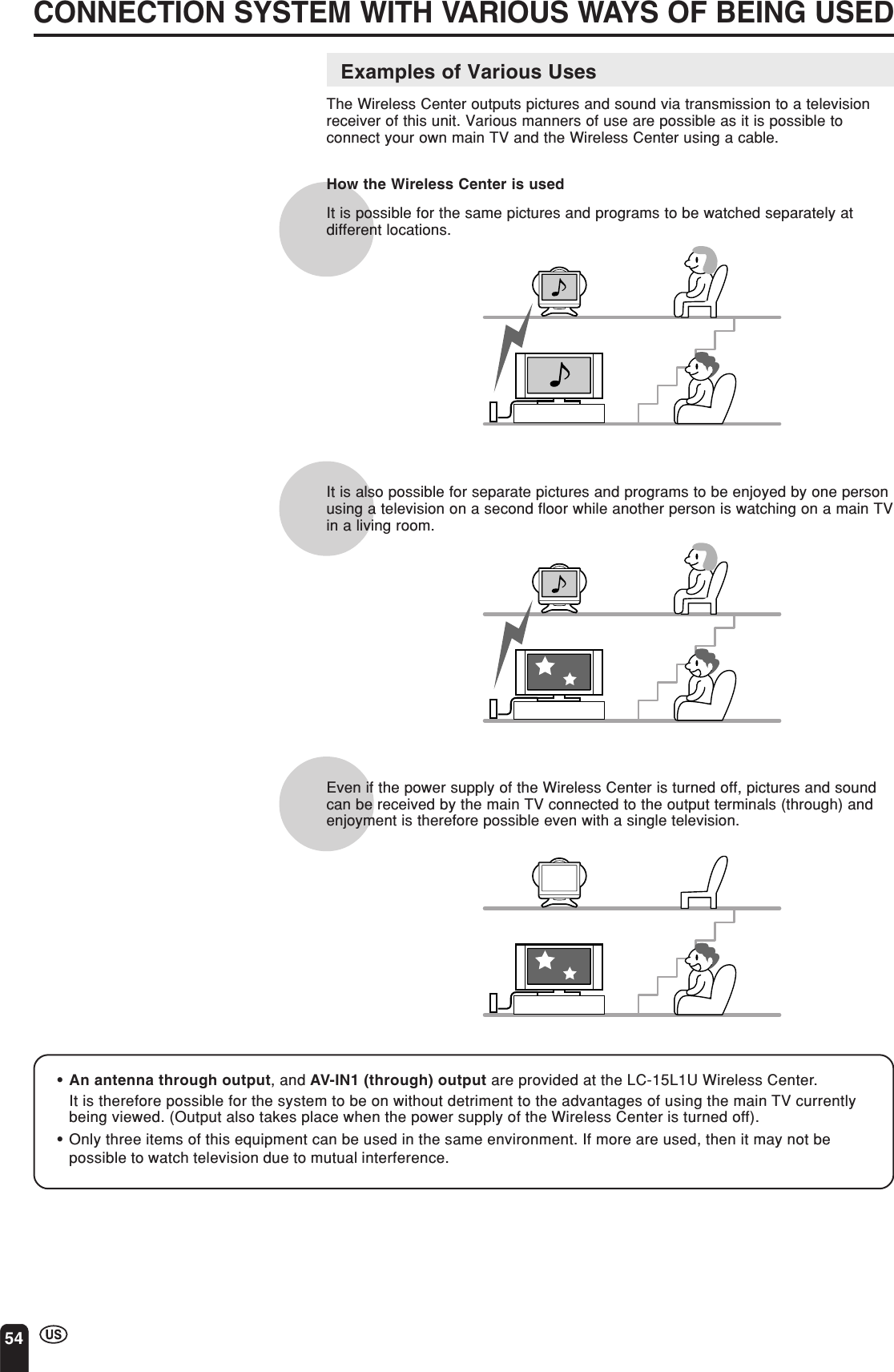
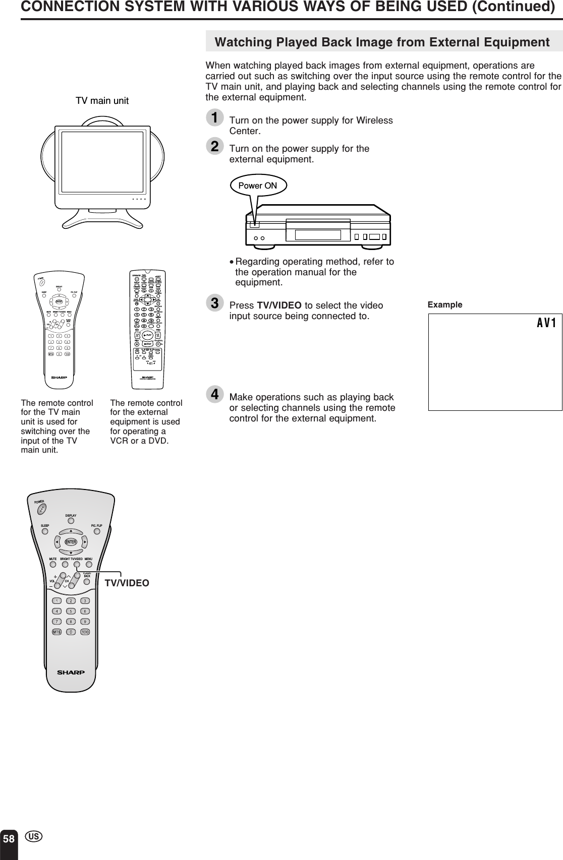
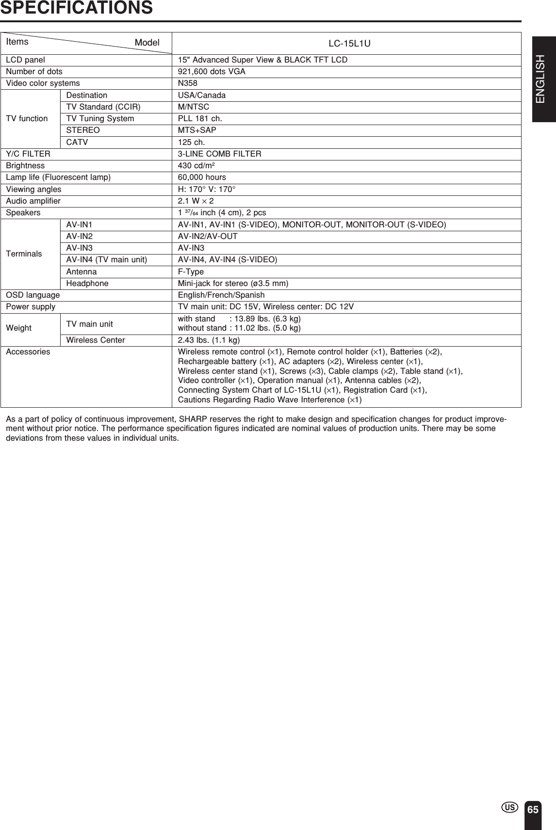
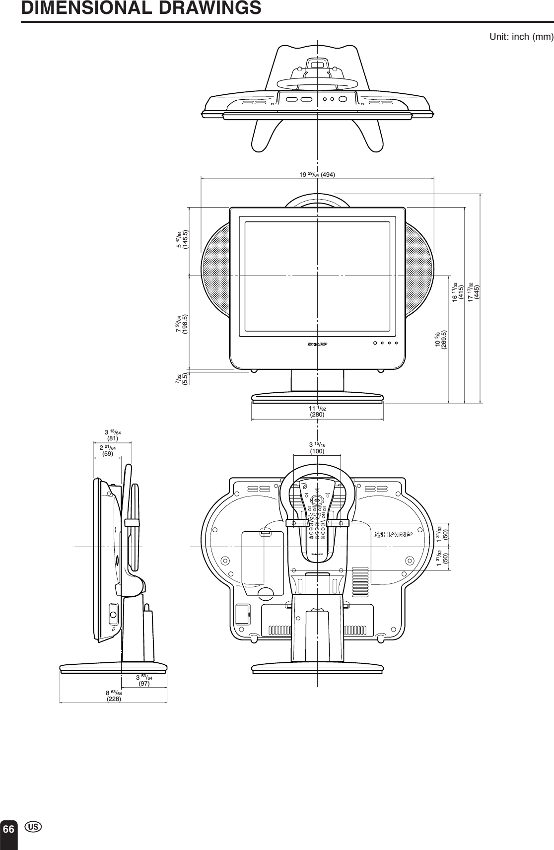
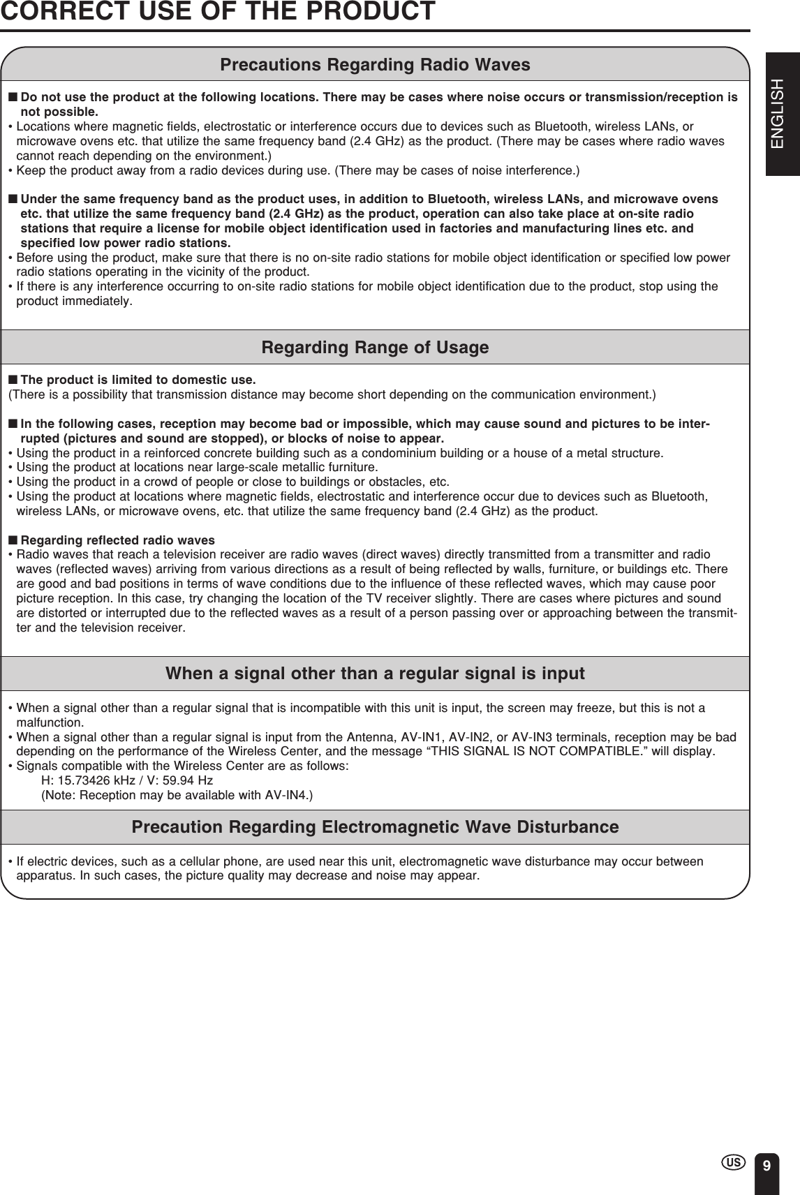
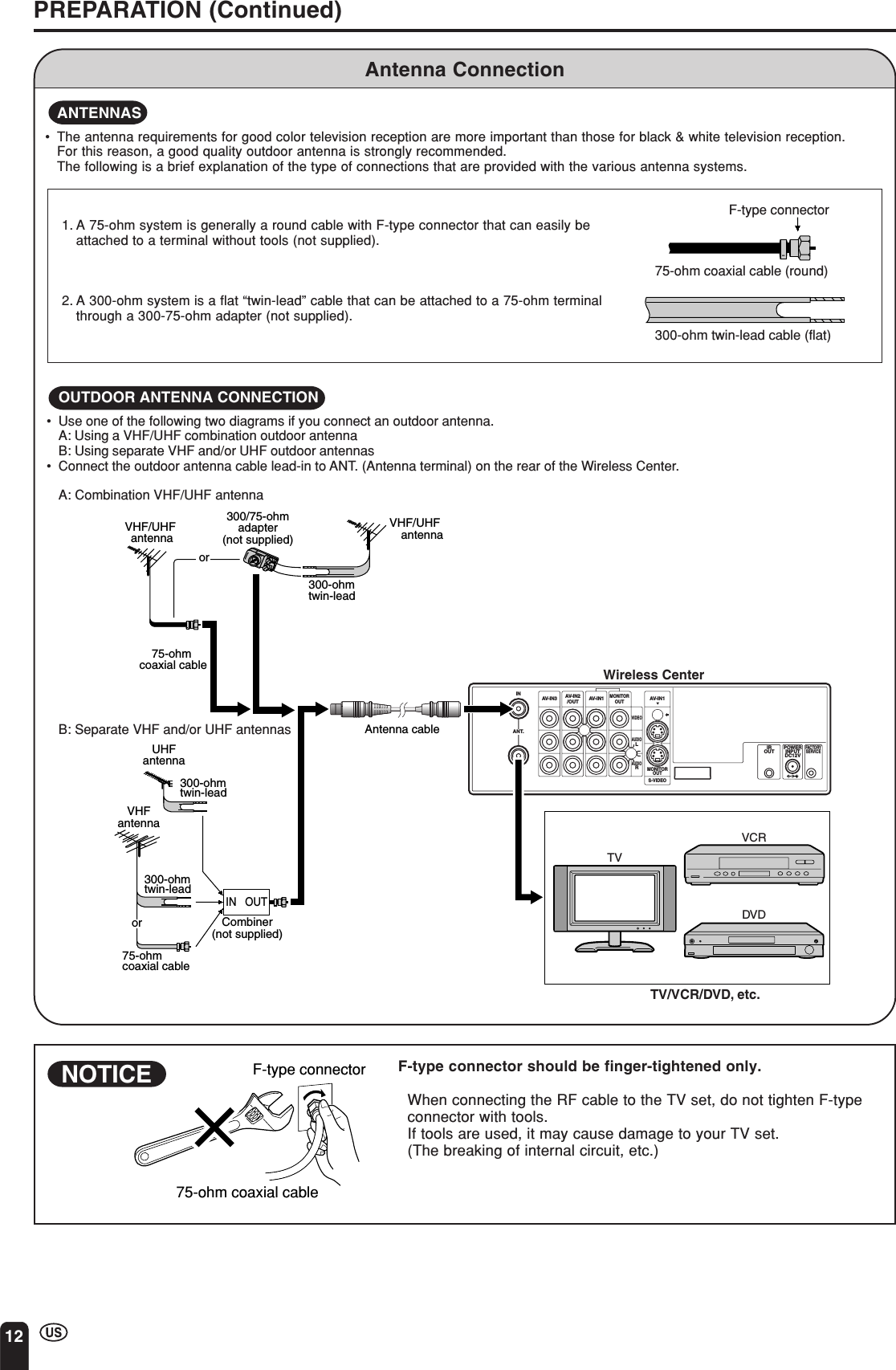
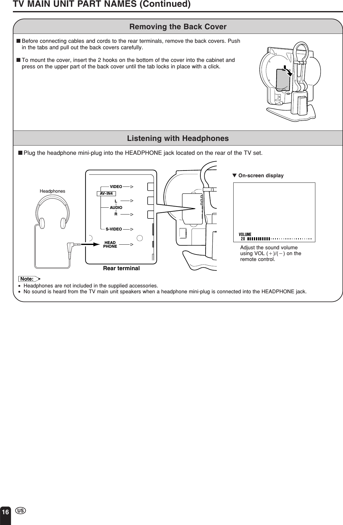
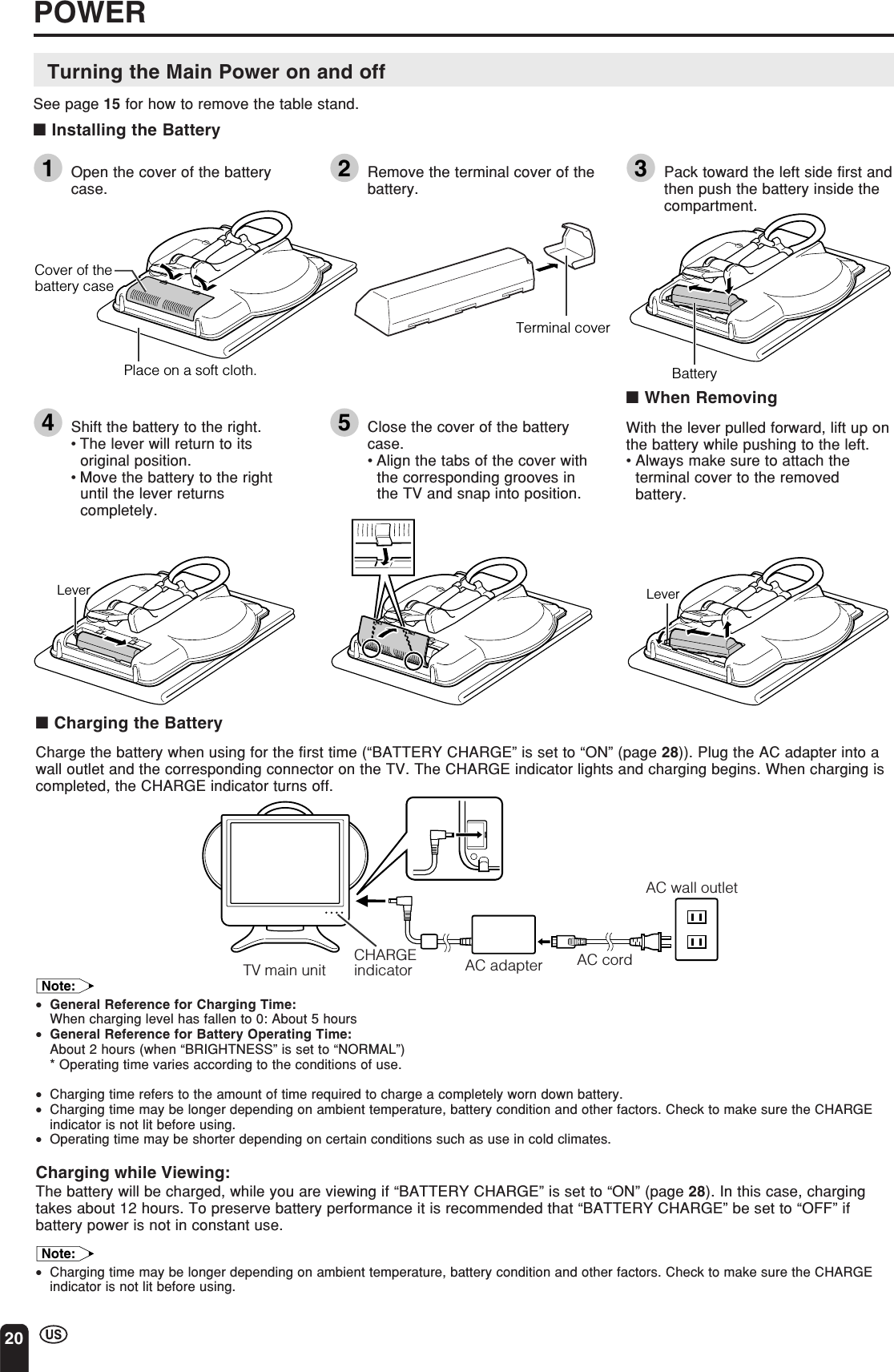
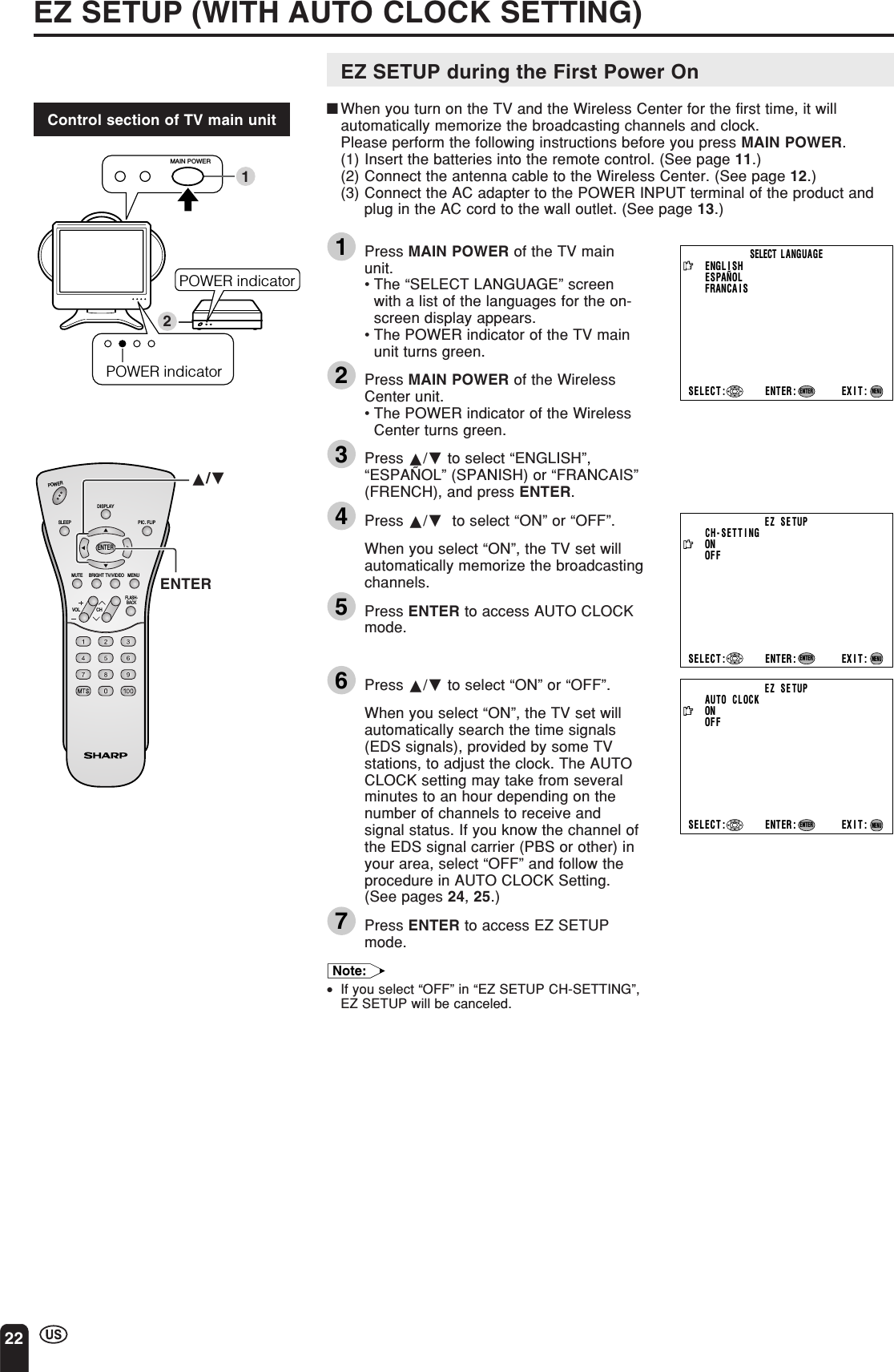
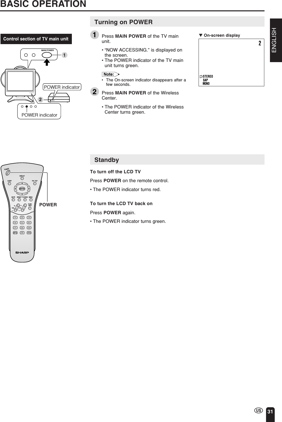
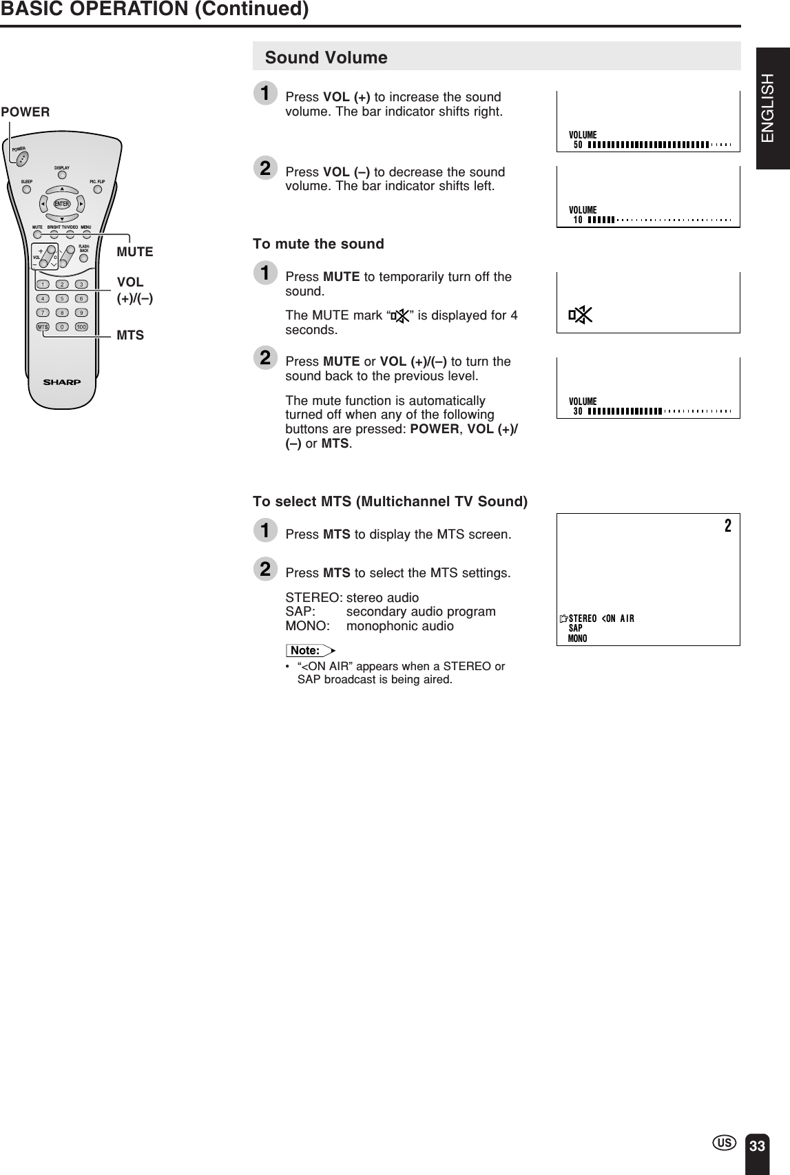
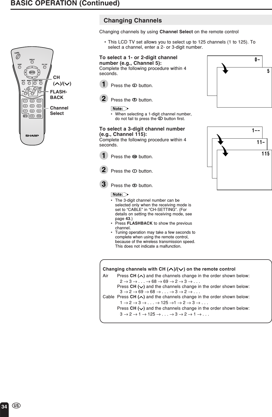
![ENGLISH3CONTENTSPageIMPORTANT INFORMATION................................... 1DEAR SHARP CUSTOMER ..................................... 4IMPORTANT SAFETY PRECAUTIONS .................. 4REGARDING BATTERY CARE ............................... 7CORRECT USE OF THE PRODUCT ....................... 9SUPPLIED ACCESSORIES ................................... 10PREPARATION....................................................... 11TV MAIN UNIT PART NAMES ............................... 14WIRELESS CENTER PART NAMES ..................... 17REMOTE CONTROL .............................................. 18OPERATION FOR TRANSMISSION AND RECEPTION OF VIDEO AND AUDIO SIGNALS ....................................... 19POWER ................................................................... 20Turning the Main Power on and off .................. 20Viewing with a Home AC Wall Outlet ............... 21EZ SETUP (WITH AUTO CLOCK SETTING) ........ 22EZ Setup during the First Power On ................ 22SETTING THE CLOCK ........................................... 24AUTO CLOCK Setting ....................................... 24MANUAL CLOCK Setting.................................. 26TV SIGNALS IN YOUR REGION ........................... 27BATTERY CHARGE AND TRANSMISSIONSETTING .............................................................. 28Battery Charge .................................................. 28Transmission Setting ......................................... 28BASIC OPERATION ............................................... 31Turning on Power .............................................. 31Standby.............................................................. 31Switching TV/VIDEO [AV1/AV2/AV3/AV4]Modes ............................................................. 32Sound Volume ................................................... 33Changing Channels ........................................... 34SELECTING MENU ITEMS .................................... 35ADJUSTMENTS ...................................................... 36Adjusting SLEEP TIMER Settings .................... 36Adjusting BRIGHTNESS Settings ..................... 37Adjusting PICTURE FLIP Settings.................... 38Adjusting PRESET Settings .............................. 39Adjusting LANGUAGE Settings ........................ 40Adjusting VIDEO ADJUST Settings .................. 41SET UP .............................................................. 43Adjusting BLUE SCREEN Settings................... 45Adjusting CLOSED CAPTION Settings ............ 46Adjusting V-CHIP Settings ................................ 47CONNECTION SYSTEM WITH VARIOUS WAYSOF BEING USED ................................................. 54Examples of Various Uses ................................ 54Connecting System Chart of LC-15L1U ........... 55Method of Connecting External Equipment ...... 56Method of Using the Video Controller .............. 57Watching Played Back Image from ExternalEquipment....................................................... 58Connecting a Home Video Game System, etc.(AV-IN4) .......................................................... 59How to Use AV-IN1 Output ............................... 60Monitor Output for Picture and Sound Outputfrom AV-IN2/OUT Terminal ............................ 61TROUBLESHOOTING ............................................ 62SPECIFICATIONS................................................... 65DIMENSIONAL DRAWINGS .................................. 66CALLING FOR SERVICE ....................................... 67LIMITED WARRANTY ............................................ 67Page](https://usermanual.wiki/Sharp/TCG041/User-Guide-395152-Page-4.png)
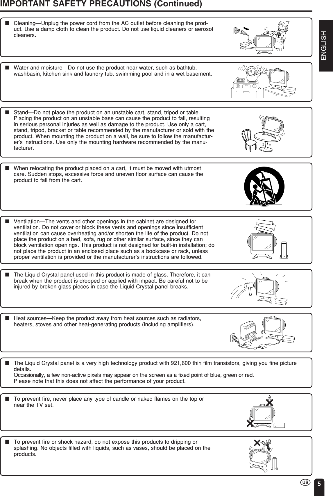
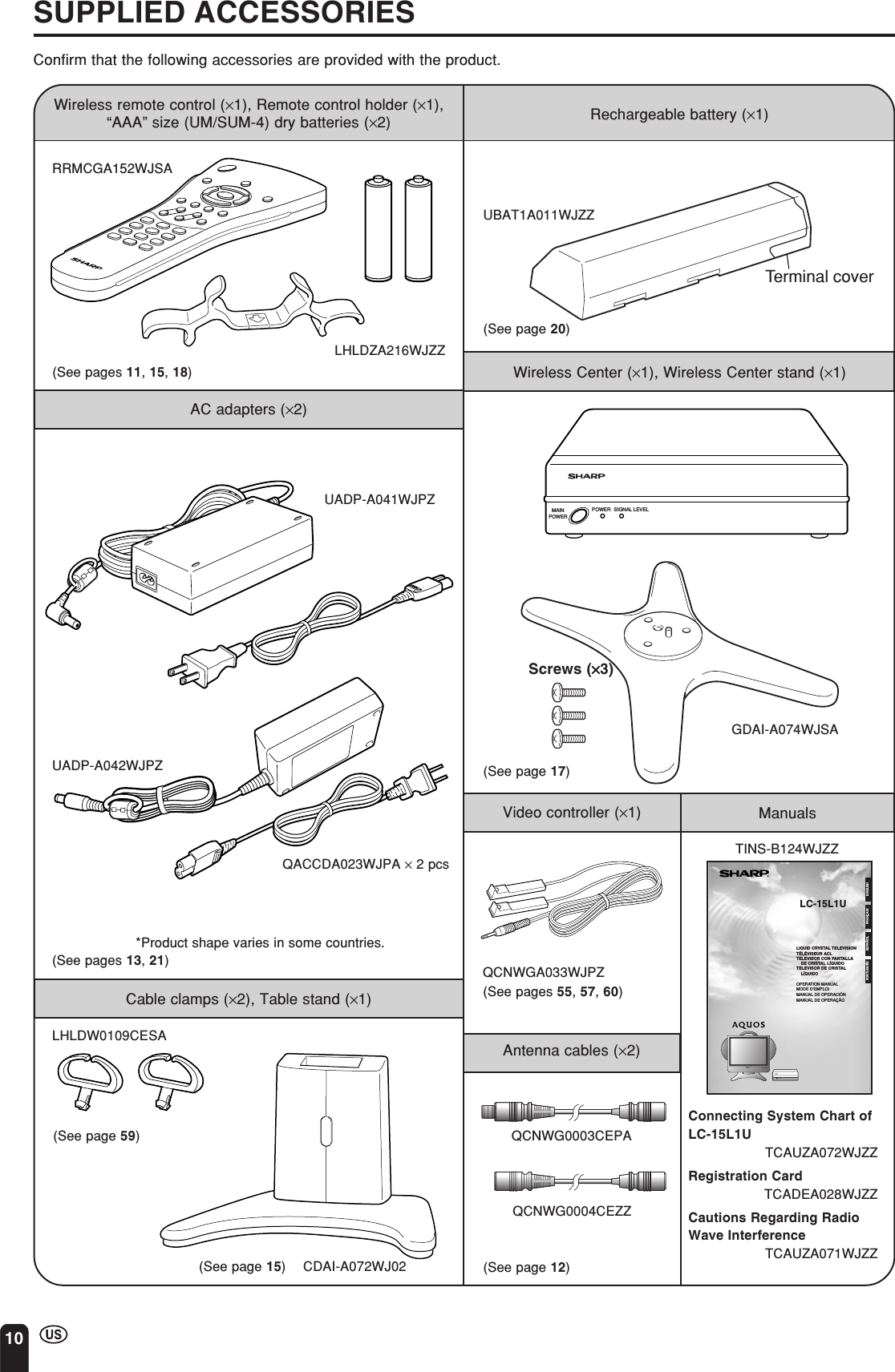
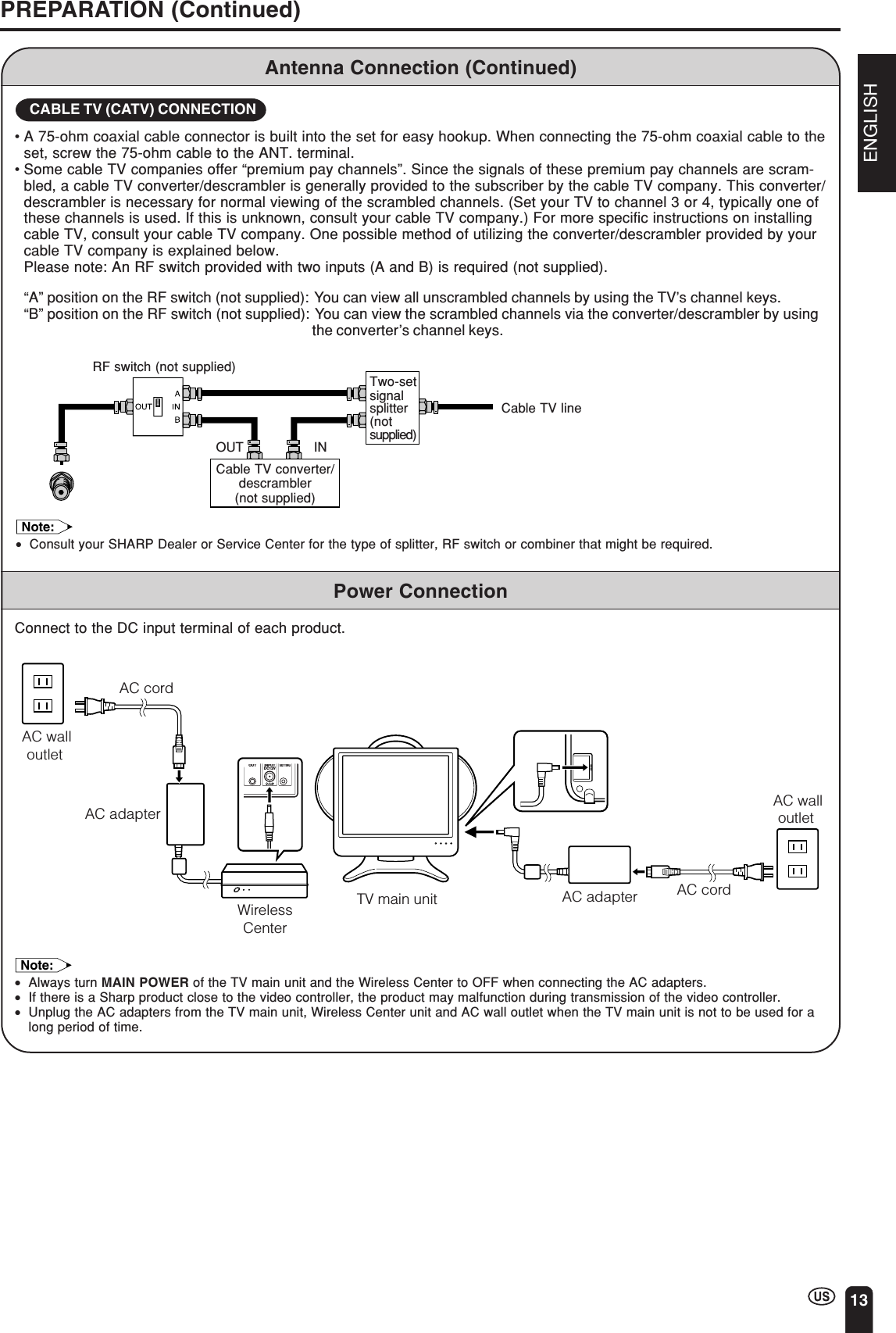
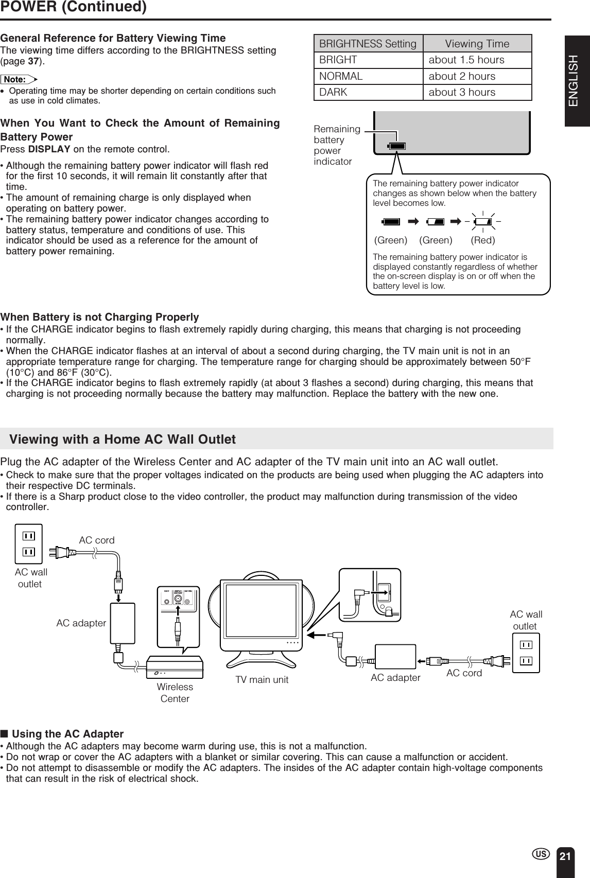
![24AUTO CLOCK SettingThere are two methods of setting the clock: AUTO CLOCK and MANUAL CLOCK.AUTO CLOCK uses EDS signals, which are provided by some TV stations, toautomatically adjust the clock. MANUAL CLOCK set the clock manually in areaswhere no channel carries EDS signals.1Press MENU to display the MENUscreen.2Press a/b to move the cursor to“SET UP”, and press ENTER.3Press a/b to move the cursor to“CLOCK”, and press ENTER.4Press a/b to move the cursor to“AUTO CLOCK”, and press ENTER.Note:•The CLOCK can be stopped completely bysetting “CLOCK” to “OFF”.SETTING THE CLOCKCLOCKAUTO CLOCKMANUAL CLOCKOFFSELECT : ENTER: EXIT:RETURNENTERMENUMENUSLEEP T IMERV IDEO ADJUSTPRESETCLOSED CAPT IONV–CHIP BLOCKSET UPSELECT : ENTER: EXIT:ENTERMENUBLUE SCREEN [OFF]LANGUAGESELECT : EXIT:ENTERRETURN SET UPCH–SETT I NGENTER:MENUCLOCKCHVOLPOWERENTERDISPLAYMUTESLEEP PIC. FLIPBRIGHT TV/VIDEO MENUFLASH-BACKENTERMENUTime reset for power outage or AC adapter disconnectedIf the TV has a power outage or the AC adapter cord is disconnected, the time display will have to be reset. In thatcase, refer to “AUTO CLOCK Setting” and “MANUAL CLOCK Setting” on pages 24 to 26.a/b](https://usermanual.wiki/Sharp/TCG041/User-Guide-395152-Page-25.png)
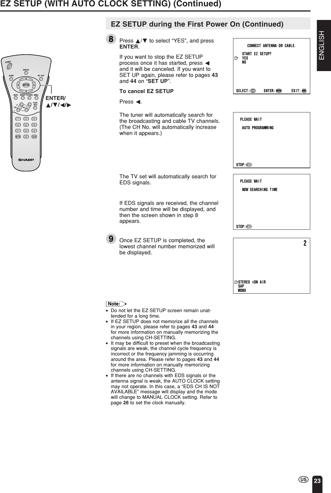
![ENGLISH25SETTING THE CLOCK (Continued)ENTER/a/b/c/dMENUAUTO CLOCKEDS CH SET [AUTO ]EXIT:RETURNEDS CH [ –––]STARTENTER:ENTERADJUST :MENUPLEASE WAITNOW SEARCH I NG T IMESTOP:2STEREO<ON A I RSAPMONOCHVOLPOWERENTERDISPLAYMUTESLEEP PIC. FLIPBRIGHT TV/VIDEO MENUFLASH-BACKAUTO CLOCK Setting (Continued)5Press a/b to move the cursor to “EDSCH SET”, and press ENTER.6Press c/d to select “AUTO” or“MANUAL”.7Press a/b to move the cursor to“START”, and press ENTER.To cancel AUTO CLOCKPress c.|If you do not know the channel that carriesEDS signals in your area, select “EDS CHSET” to “AUTO” and select “START”. Ifyou know the channel of the EDS signalcarrier in your area, select “EDS CH SET”to “MANUAL”. Set the EDS CH and select“START”.|When set to “AUTO CLOCK”, the time isacquired automatically when MAINPOWER is turned OFF. (This function willnot work when EDS CH is not set.)Note:•CLOCK: The AUTO CLOCK setting may takefrom several minutes to an hour depending on thenumber of channels to receive and signal status.•If there are no channels with EDS signals or theantenna signal is weak, the AUTO CLOCK settingmay not operate. In this case, an “EDS CH ISNOT AVAILABLE” message will display, and theMANUAL CLOCK Setting screen appears. Referto “MANUAL CLOCK Setting” on page 26 to setthe clock manually.•If you know the Channel of the EDS signal carrierin your area, set “EDS CH SET” to “MANUAL”and select “START”. In case, the message “EDSCH (XXX) EDS DATA IS NOT AVAILABLE”displays, set “EDS CH SET” to “AUTO” when theAUTO CLOCK setting screen appears.•If broadcasting channels are not memorized, EDSsignals cannot be received even when the “EDSCH SET” is set to “AUTO”. In this case, try EZSETUP again. (See page 43.)](https://usermanual.wiki/Sharp/TCG041/User-Guide-395152-Page-26.png)
![26MANUAL CLOCK SettingIf there are no channels with EDS signals, set the clock manually using MANUALCLOCK.1Press MENU to display the MENUscreen.2Press a/b to move the cursor to“SET UP”, and press ENTER.3Press a/b to move the cursor to“CLOCK”, and press ENTER.4Press a/b to move the cursor to“MANUAL CLOCK”, and press ENTER.5Press a/b to move the cursor to“TIME”, and press ENTER.6Press c/d to set the time, and pressENTER.12:00AM 11:59AM11:59PM 12:00PMNote:•Make sure to press ENTER after adjustingthe time. Otherwise, the time will not beset.7Press MENU to return to the mainscreen.SETTING THE CLOCK (Continued)ENTER/a/b/c/dMENUDaylight Saving-Time (DST) AdjustmentThe Daylight Saving-Time changes as shown below. Set the “DST” to “ON” to forward the clock by 1 hour. To rewindthe clock by 1 hour, set the “DST” to “OFF”.(Spring)On the first Sunday in April D.S.T. starts.(Autumn)On the last Sunday in October D.S.T. finishes.Advances 1 hour.Rewinds 1 hour.CHVOLPOWERENTERDISPLAYMUTESLEEP PIC. FLIPBRIGHT TV/VIDEO MENUFLASH-BACKMENUSLEEP T IMERPRESETCLOSED CAPT IONV–CHIP BLOCKSET UPSELECT : EXIT:V IDEO ADJUSTENTER:ENTERMENUCLOCKAUTO CLOCKMANUAL CLOCKOFFSELECT : ENTER: EXIT:RETURNENTERMENUMANUAL CLOCKT IME [ 12: 00AM]EXIT:RETURNDST [OFF ]ENTER:ENTERADJUST :MENUBLUE SCREEN [OFF]LANGUAGESELECT : EXIT:ENTERRETURN SET UPCH–SETT I NGENTER:MENUCLOCK1:00AM 2:00AM3:00AM 4:00AM1:00AM 2:00AM1:00AM 2:00AM](https://usermanual.wiki/Sharp/TCG041/User-Guide-395152-Page-27.png)

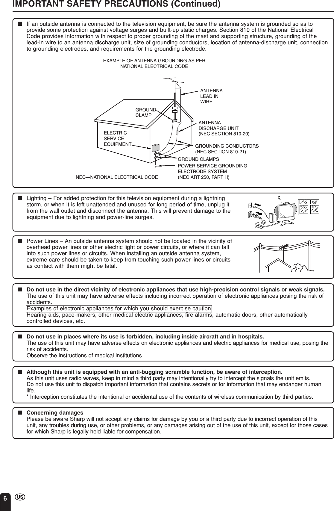
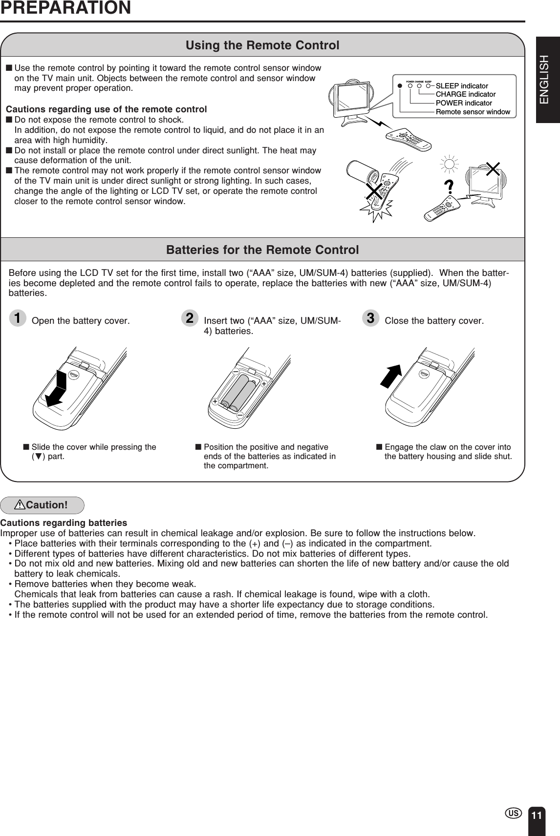
![28BATTERY CHARGE AND TRANSMISSION SETTINGBattery ChargeThe “BATTERY CHARGE” is set to “ON” when shipped from the factory. Thebattery will deteriorate if it continues to be charged after having been fully charged.It is recommended to set the “BATTERY CHARGE” to “OFF” when the batteryis not used frequently.1Press MENU to display the MENUscreen.2Press a/b to move the cursor to“PRESET”, and press ENTER.3Press a/b to move the cursor to“BATTERY CHARGE”, and pressENTER.4Press c/d to change the setting, andpress ENTER.5Press MENU to return to the mainscreen.Transmission SettingWhen shipped from the factory, the “CHANNEL” of the “TRANSMISSIONSETTING” is set to “AUTO”, and the “DISTANCE” is set to “NEAR”. However,when reception is poor due to the presence of an interference source in closeproximity, change the settings for “CHANNEL” or “DISTANCE” to ensure normalreception.ENTER/a/b/c/dMENU[1] Preparing for “TRANSMISSION SETTING”1Connect the antenna to the WirelessCenter.2Install the Wireless Center and TVreceiver next to each other.3Turn on the power for both the WirelessCenter and TV receiver.4Press MENU to display the MENUscreen.CHVOLPOWERENTERDISPLAYMUTESLEEP PIC. FLIPBRIGHT TV/VIDEO MENUFLASH-BACKMENUSLEEP T IMERV IDEO ADJUSTPRESETCLOSED CAPT IONV–CHIP BLOCKSET UPSELECT : ENTER: EXIT:ENTERMENUAC cordAC walloutlet AC adapterWirelessCenterTransmissionTV main unitNOW ACCESSING.BR I GHTNESS [ BR I GHT ]MTSAUTO POWER OFFRETURN[STEREO][OFF ]PICTURE FLIPAV2 IN/OUTBATTERY CHARGE[NORMAL ][IN ][ON ]PRESETTRANSMISSION SETTINGSELECT : ENTER: EXIT:ENTERMENU](https://usermanual.wiki/Sharp/TCG041/User-Guide-395152-Page-29.png)
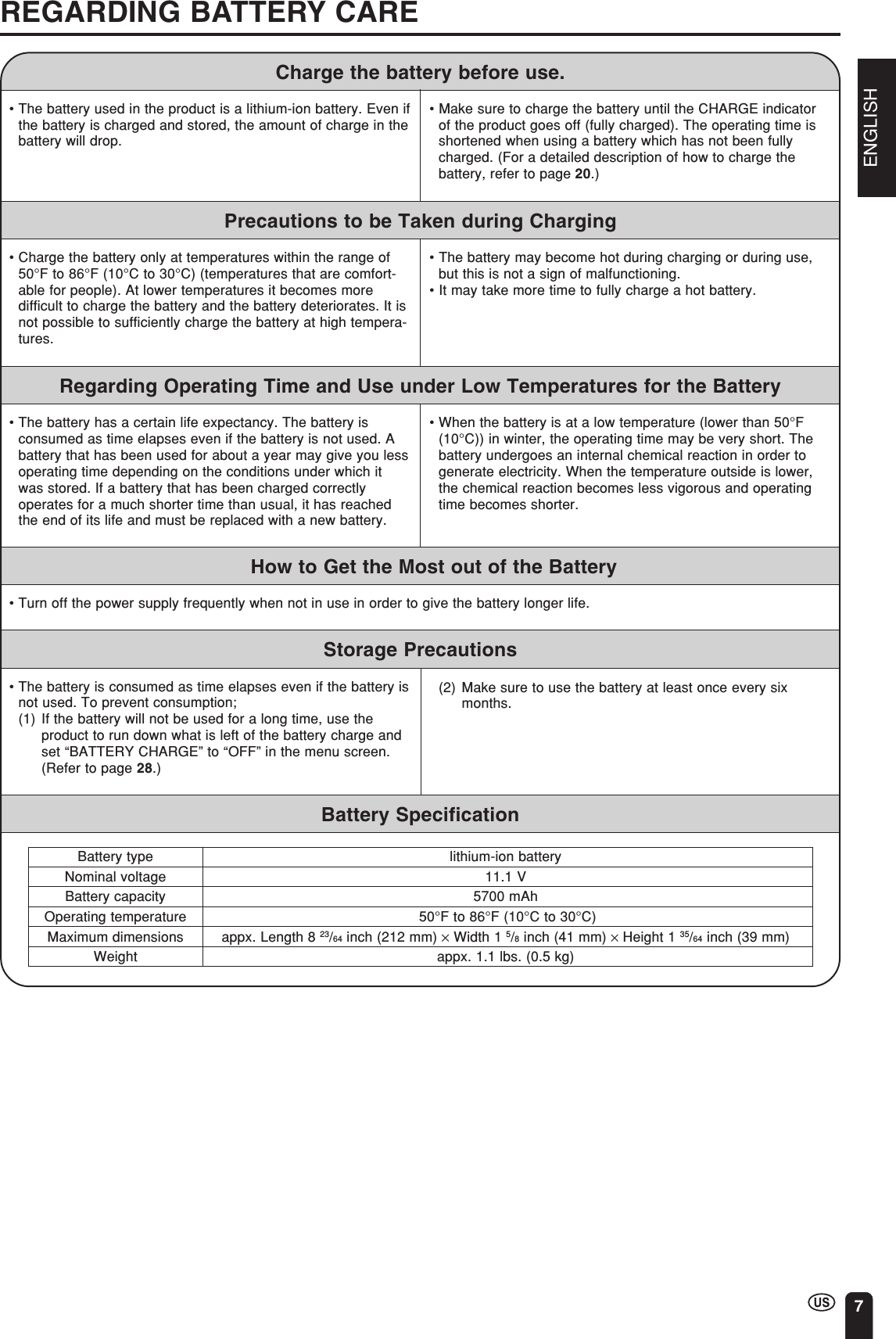
![ENGLISH29Transmission Setting (Continued)5Press a/b to move the cursor to“PRESET”, and press ENTER.6Press a/b to move the cursor to“TRANSMISSION SETTING”, and pressENTER.[2] Setting ChannelFour settings can be selected for the communication channel consisting ofAuto, A, B and C. When set to “AUTO”, available channels that can betransmitted are set automatically. It is recommended to normally set thecommunication channel to “AUTO”.AUTO A B C1Press a/b to select “CHANNEL”, andthen press ENTER.2Press c/d to select “AUTO”, and thenpress ENTER.•The available settings change in theorder shown below each time c/d ispressed.AUTO A B C•“ADJUSTING CHANNEL SETTING.” isdisplayed on the screen and thecommunication channel is setautomatically.MENUSLEEP T IMERV IDEO ADJUSTPRESETCLOSED CAPT IONV–CHIP BLOCKSET UPSELECT : ENTER: EXIT:ENTERMENUBR I GHTNESS [ BR I GHT ]MTSAUTO POWER OFFRETURN[STEREO][OFF ]PICTURE FLIPAV2 IN/OUTBATTERY CHARGE[NORMAL ][IN ]PRESETTRANSMISSION SETTINGSELECT : ENTER: EXIT:ENTERMENU[ON ]STATUS: A[ A]DISTANCERETURN[ FAR] STATUS: NEARTRANSMISSION SETTINGCHANNELSELECT : ENTER: EXIT:ENTERMENUDisplayed in yellowBATTERY CHARGE AND TRANSMISSION SETTING (Continued)ADJUSTING CHANNEL SETTING.CHVOLPOWERENTERDISPLAYMUTESLEEP PIC. FLIPBRIGHT TV/VIDEO MENUFLASH-BACKENTER/a/b/c/dMENU[ AUTO ]DISTANCERETURN[ FAR] STATUS: NEARTRANSMISSION SETTINGCHANNELSELECT : ENTER: EXIT:ENTERMENUNote:•If “CHANNEL” is set to “AUTO”, when switching on the power or when setting thecommunication channel, a connection is automatically made to an empty channel A,B, or C.∗As this is not the function to automatically switch channels to an empty channelwhen the reception conditions deteriorate, try to switch manually to anotherchannel with better reception conditions in such a case.•This unit uses the three communication channels A, B, and C for wirelesstransmission of video and audio signals.When microwave ovens, wireless LANs, or devices using Bluetooth transmissiontechnology that use the same 2.4GHz frequency band are operating in the vicinity,they may cause interference possibly making reception impossible.In this case, changing to another transmission channel may avoid this type ofinterference.](https://usermanual.wiki/Sharp/TCG041/User-Guide-395152-Page-30.png)
![30■Errors on the communication conditions1Press a/b to select “DISTANCE”, andthen press ENTER.2Press c/d to select the desireddistance, and then press ENTER.•“ADJUSTING DISTANCE SETTING.” isdisplayed on the screen and thecommunication distance is setautomatically.3Press MENU to return to the mainscreen.Note:•Automatic channel selection is only madewhen the TV main unit is first switched onor when the function is selected from themenu.•If reception has become poor afterchanging the locations of the WirelessCenter and TV receiver, the problem maybe corrected by resetting thecommunication channel andcommunication distance.Transmission Setting (Continued)[3] Setting DistanceSelect the DISTANCE mode that gives the best reception and picture quality.FARMIDNEARSettingPicture QualityData ErrorCorrectionNEARBestWeakWorstStrongMID FARBATTERY CHARGE AND TRANSMISSION SETTING (Continued)STATUS: ADISTANCERETURN[ FAR] STATUS: NEARTRANSMISSION SETTINGCHANNEL [ AUTO]Displayed in yellowADJUST ING D I STANCE SETT I NG.CHVOLPOWERENTERDISPLAYMUTESLEEP PIC. FLIPBRIGHT TV/VIDEO MENUFLASH-BACKSTATUS: ADISTANCERETURN[NEAR]TRANSMISSION SETTINGCHANNEL [ AUTO]ENTER/a/b/c/dMENUNEAR: Enables finer picture quality.MID: Enables normal picturequality and middle distancetransmission.FAR: Enables longer distancetransmission. (Picture qualitybecomes relatively poor.)Error messageSIGNAL COULD NOTBE RECEIVEDSIGNAL COULD NOTBE RECEIVEDWEAK SIGNALColorRedYellowYellowDescriptionContinues to be indicated as long as no signal isreceived.Indicates no connection can be made to theWireless Center due to interference of radiowaves. The indication is red initially, andchanges to yellow after approximately 10seconds. When using a fixed channel (A, B,or C), set to “AUTO” or try switching to anotherchannel to connect to the Wireless Center.Is indicated for 10 seconds, then goes outtemporarily. This operation is repeated every 10minutes.* Interference of radio waves denotes radio waves in the 2.4GHz frequency waveband complying with the IEEE802.11b specifications. Since this function cannotdetect radio waves in the 2.4GHz frequency wave band other than those thatcomply with the IEEE802.11b specifications, no yellow indication will appear shouldsuch radio waves be the cause of interference.](https://usermanual.wiki/Sharp/TCG041/User-Guide-395152-Page-31.png)
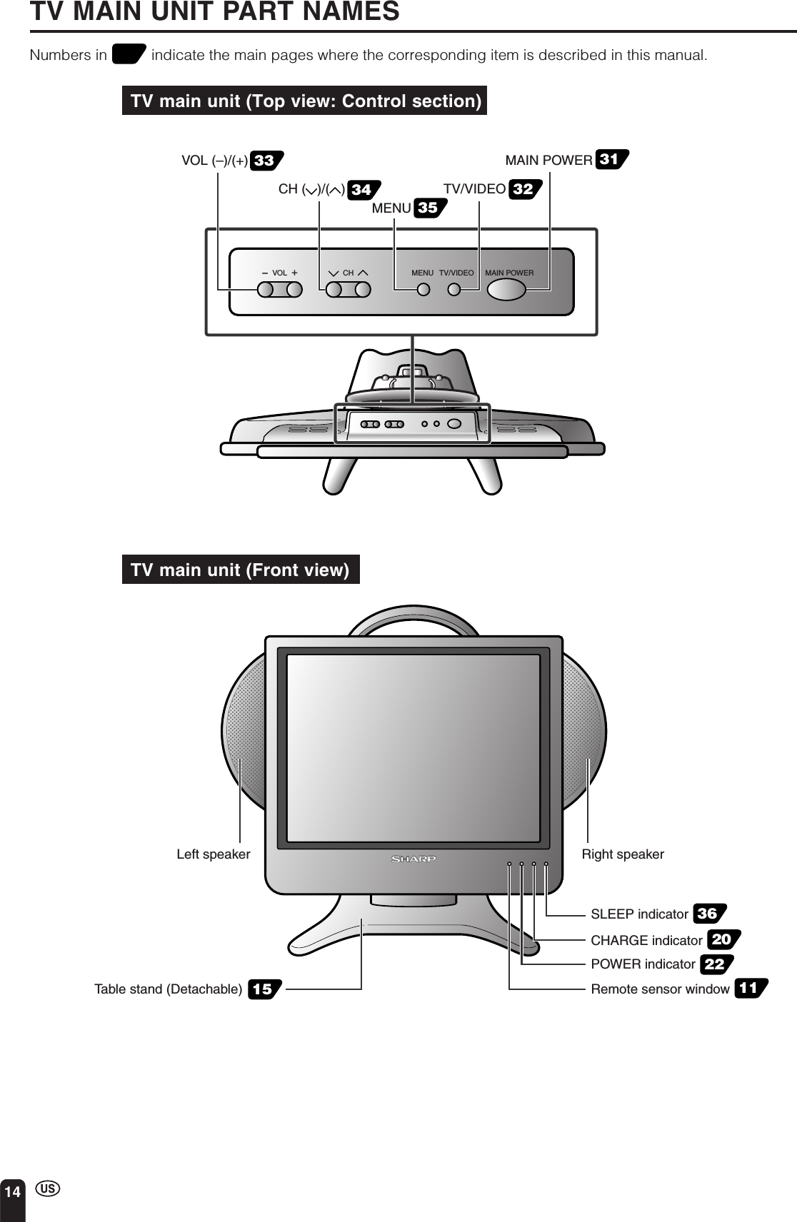
![32BASIC OPERATION (Continued)Switching TV/VIDEO [AV1/AV2/AV3/AV4] Modes1Turn on the power of the connectedvideo equipment.2Press TV/VIDEO and select theapplicable input source. The screendisplays AV1, AV2, AV3, AV4 or TVmode each time TV/VIDEO is pressed.Note:•The AV input mode indication remains for3 seconds.•AV1: Video equipment connected to the AV-IN1input terminals.The S-video input terminal is additionallyprovided for the AV-IN1 input.If both the S-video terminal and normalvideo terminals are connected with cables,the S-video input terminal takes priority.•AV2: AV2 mode is used to adjust the presetsettings and “IN” or “OUT” can be selected.AV2 indication is not displayed when “OUT”is selected. (For details on setting AV2 IN/OUT, see page 39.)•AV3: Video equipment connected to the AV-IN3input terminals.•AV4: The AV4 input terminal is in the TV mainunit. This terminal is for directly connectingto an external device such as a gamedevice.If both the S-video terminal and normalvideo terminals are connected with cables,the S-video input terminal takes priority.CHVOLPOWERENTERDISPLAYMUTESLEEP PIC. FLIPBRIGHT TV/VIDEO MENUFLASH-BACKTV/VIDEOAV2AV312AV1AV4STEREO<ON A I RSAPMONOAV1 modeAV2 modeTV modeAV3 modeAV4 mode](https://usermanual.wiki/Sharp/TCG041/User-Guide-395152-Page-33.png)
![ENGLISH35•This LCD TV set allows you to adjust the various settings using the MENUscreen. Select the desired menu item by following the steps below and thenrefer to the indicated page for details.1Press MENU to display the MENUscreen.2Press a/b to select the desired menuitem, and press ENTER.3Press MENU to exit.SELECTING MENU ITEMSNote:•The displayed items differ depending on thesetting conditions.•The selected item changes to yellow.•Items in magenta cannot be selected.•To return to the previous screen, select“RETURN”.•You can adjust some settings with the specialbuttons: SLEEP, BRIGHT and PIC. FLIP (seepages 36 to 38).* The illustrations and on-screen displays in thisoperation manual are for explanation purposesand may vary slightly from the actual opera-tions.ENTERBRIGHTMENUSLEEP T IMERV IDEO ADJUSTPRESETCLOSED CAPT IONV–CHIP BLOCKSET UPSELECT : ENTER: EXIT:ENTERMENUBRIGHTNESS [ BR IGHT ]MTSAUTO POWER OFFRETURN[STEREO][OFF ]PICTURE FLIPAV2 IN/OUT [NORMAL ][IN ][ ON ]PRESETTRANSMISSION SETTINGPICTURE [ 50]TINTCOLORBLACK LEVELSHARPNESSSELECT : ENTER: EXIT:V I DEO ADJUST ( TV )RETURN[ 0][ 0][ 0][ 0]RED-BLUE [ 0]GREEN [ 0]RESETENTERMENUSLEEP T IMERSELECT : ENTER: EX I T :ENTERRETURNSLEEP T IMER [––– REMAIN]ENTERENTER:CC/ TEXT [OFF]SELECT : EXIT:RETURN CLOSED CAPT IONINPUT SECRET NO.– – – –EXIT:MENUMENUMENUSELECT : ENTER: EXIT:ENTERMENUBLUE SCREEN [OFF]LANGUAGESELECT : EX I T :ENTERRETURN SET UPCH–SETT INGENTER:MENUCLOCKBATTERY CHARGECHVOLPOWERENTERDISPLAYMUTESLEEP PIC. FLIPBRIGHT TV/VIDEO MENUFLASH-BACKMENUPIC. FLIPSLEEPa/b](https://usermanual.wiki/Sharp/TCG041/User-Guide-395152-Page-36.png)
![36ADJUSTMENTSAdjusting SLEEP TIMER SettingsYou can set the SLEEP TIMER to automatically turn off the TV.Directly setting the SLEEP TIMER1Press SLEEP to display the SLEEPTIMER screen.2Press SLEEP to set the sleep timer (inminutes).---12030 6090(minutes)150•The SLEEP TIMER is turned off when“---” is displayed.Note:•The SLEEP TIMER screen automaticallydisappears in 3 seconds.Setting the SLEEP TIMER on theMENU screen1Press MENU to display the MENUscreen.2Press a/b to move the cursor to“SLEEP TIMER”.3Press ENTER to display the SLEEPTIMER screen, and press ENTER.4Press c/d to set the sleep timer (inminutes), and press ENTER.•The time can be set in increments of30 minutes and in the range between30 and 150 minutes.•The SLEEP TIMER is turned off when“---” is displayed.5Press MENU to return to the mainscreen.Note:•When you set the SLEEP TIMER, the SLEEPindicator lights up red.•After you set the SLEEP TIMER, pressing MAINPOWER on the TV set or POWER on the remotecontrol will cancel the SLEEP TIMER setting andthe SLEEP indicator goes out.•5 minutes before the SLEEP TIMER turns off theTV, “5 REMAIN” is displayed on the screen for 4seconds. The SLEEP TIMER counts down andshows a similar 4-second display for eachremaining minute until the timer turns off the TV.––– REMA I N60 REMAINSLEEP T IMERSELECT : EXIT:RETURNSLEEP T IMER [––– REMAIN]ENTER:ENTERMENUSLEEP T IMERRETURNSLEEP T IMER [–60 REMAIN]MENUSLEEP T IMERV IDEO ADJUSTPRESETCLOSED CAPT IONV–CHIP BLOCKSET UPSELECT : ENTER: EXIT:ENTERMENUCHVOLPOWERENTERDISPLAYMUTESLEEP PIC. FLIPBRIGHT TV/VIDEO MENUFLASH-BACKSLEEPCHVOLPOWERENTERDISPLAYMUTESLEEP PIC. FLIPBRIGHT TV/VIDEO MENUFLASH-BACKENTER/a/b/c/dMENUPOWER](https://usermanual.wiki/Sharp/TCG041/User-Guide-395152-Page-37.png)
![ENGLISH37ADJUSTMENTS (Continued)BR IGHTNESS[BR IGHT ]MENUSLEEP T IMERV IDEO ADJUSTPRESETCLOSED CAPT IONV–CHIP BLOCKSET UPSELECT : ENTER: EXIT:ENTERMENUBRIGHTNESS [BRI GHT ]MTSAUTO POWER OFFRETURN[STEREO][OFF ]PICTURE FLIPBATTERY CHARGEAV2 IN/OUT [NORMAL ][IN ][ON ]PRESETTRANSMISSION SETTINGSELECT : ENTER: EXIT:ENTERMENUCHVOLPOWERENTERDISPLAYMUTESLEEP PIC. FLIPBRIGHT TV/VIDEO MENUFLASH-BACKENTER/a/b/c/dCHVOLPOWERENTERDISPLAYMUTESLEEP PIC. FLIPBRIGHT TV/VIDEO MENUFLASH-BACKBRIGHTMENUAdjusting BRIGHTNESS SettingsYou can adjust the brightness of the screen.Directly setting the BRIGHTNESS1Press BRIGHT to display theBRIGHTNESS screen.2Press BRIGHT to change the setting.BRIGHTDARKNORMALNote:•The BRIGHTNESS screen automaticallydisappears in 3 seconds.•[BRIGHT]: maximum brightness[NORMAL]:60% brightness (Suitable forviewing in a well-lit area. Savesenergy.)[DARK]: 10% brightness (Sufficientlybright when viewing in dimareas.)Setting the BRIGHTNESS on the MENUscreen1Press MENU to display the MENUscreen.2Press a/b to move the cursor to“PRESET”, and press ENTER.3Press a/b to move the cursor to“BRIGHTNESS”, and press ENTER.4Press c/d to change the setting, andpress ENTER.5Press MENU to return to the mainscreen.](https://usermanual.wiki/Sharp/TCG041/User-Guide-395152-Page-38.png)
![38ADJUSTMENTS (Continued)P I CTURE FL I P [ NORMAL]PICTURE FLIP [MIRROR]PI CTURE FL I P [ROTATE ]P I CTURE FL I P [UPS I DE DOWN]ABCABCABCABCMENUSLEEP T IMERV IDEO ADJUSTPRESETCLOSED CAPT IONV–CHIP BLOCKSET UPSELECT : ENTER: EXIT:ENTERMENUCHVOLPOWERENTERDISPLAYMUTESLEEP PIC. FLIPBRIGHT TV/VIDEO MENUFLASH-BACKENTER/a/b/c/dCHVOLPOWERENTERDISPLAYMUTESLEEP PIC. FLIPBRIGHT TV/VIDEO MENUFLASH-BACKPIC. FLIPMENUAdjusting PICTURE FLIP SettingsYou can set the orientation of the picture.Directly setting the PICTURE FLIP1Press PIC. FLIP to display the PICTUREFLIP screen.2Press PIC. FLIP to change the setting.MIRROR ROTATENORMAL UPSIDE DOWNNote:•The PICTURE FLIP screen automaticallydisappears in 3 seconds.•[NORMAL]: normal image[MIRROR]: mirror image[ROTATE]: rotated image[UPSIDE DOWN]: upside down imageSetting the PICTURE FLIP on theMENU screen1Press MENU to display the MENUscreen.2Press a/b to move the cursor to“PRESET”, and press ENTER.3Press a/b to move the cursor to“PICTURE FLIP”, and press ENTER.4Press c/d to change the setting, andpress ENTER.5Press MENU to return to the mainscreen.BRIGHTNESS [BRI GHT ]MTSAUTO POWER OFFRETURN[STEREO][OFF ]PICTURE FLIPBATTERY CHARGEAV2 IN/OUT [NORMAL ][IN ][ON ]PRESETTRANSMISSION SETTINGSELECT : ENTER: EXIT:ENTERMENU](https://usermanual.wiki/Sharp/TCG041/User-Guide-395152-Page-39.png)
![ENGLISH39ADJUSTMENTS (Continued)MENUSLEEP T IMERV IDEO ADJUSTPRESETCLOSED CAPT IONV–CHIP BLOCKSET UPSELECT : ENTER: EXIT:ENTERMENUSelected item Factory setting Setting optionsTRANSMISSION SETTING See page 28.BRIGHTNESS [BRIGHT] Maximum brightness [NORMAL] Brightness 60% → Suitable for viewing in a well-lit area.Saves energy.[DARK] Brightness 10% →Sufficiently bright when viewing in dim areas.MTS*1 [STEREO] STEREO AUDIO [SAP] SECONDARY AUDIO PROGRAM[MONO] Monophonic audioAUTO POWER OFF [OFF] The function is disabled. [ON] The function automatically turns off power supply if a no-signal state(only TV mode) continues for a specified time (five minutes).PICTURE FLIP [NORMAL] Normal image orientation [MIRROR] Mirror image →To display mirror images for special uses.[ROTATE] Rotated image →To display rotated images for special uses.[UPSIDE DOWN] Upside down image →To display images upside down forspecial uses.AV2 IN/OUT*2[IN] AV-IN2 terminals selected [OUT ] Line Output is selected, Output volume is fixed, Speaker as inputterminals output is available.BATTERY CHARGE [ON] See page 28.*1In AV1, AV2, AV3 or AV4 mode, MTS displayed in magenta cannot be selected.*2When “AV2 IN/OUT” is set to “OUT” and TV/VIDEO is pressed to select “AV4”, the images received through the antenna will be output.ENTER/a/b/c/dMENUCHVOLPOWERENTERDISPLAYMUTESLEEP PIC. FLIPBRIGHT TV/VIDEO MENUFLASH-BACKABCABCABCABCAdjusting PRESET Settings1Press MENU to display the MENUscreen.2Press a/b to move the cursor to“PRESET”, and press ENTER.3Press a/b to move the cursor to thedesired item, and press ENTER.4Press c/d to change the setting, andpress ENTER.5Press MENU to return to the mainscreen.BRIGHTNESS [BRI GHT ]MTSAUTO POWER OFFRETURN[STEREO][OFF ]PICTURE FLIPBATTERY CHARGEAV2 IN/OUT [NORMAL ][IN ][ON ]PRESETTRANSMISSION SETTINGSELECT : ENTER: EXIT:ENTERMENU](https://usermanual.wiki/Sharp/TCG041/User-Guide-395152-Page-40.png)
![40CHVOLPOWERENTERDISPLAYMUTESLEEP PIC. FLIPBRIGHT TV/VIDEO MENUFLASH-BACKAdjusting LANGUAGE SettingsThe language for the On-Screen Display can be ENGLISH, SPANISH or FRENCH.1Press MENU to display the MENUscreen.2Press a/b to move the cursor to“SET UP”, and press ENTER.3Press a/b to move the cursor to“LANGUAGE”, and press ENTER.4Press a/b to select the language, andpress ENTER.ADJUSTMENTS (Continued)ENTERMENUa/bMENUSLEEP T IMERV IDEO ADJUSTPRESETCLOSED CAPT IONV–CHIP BLOCKSET UPSELECT : ENTER: EXIT:ENTERMENUMENUSLEEP T IMERV IDEO ADJUSTPRESETCLOSED CAPT IONV–CHIP BLOCKSET UPSELECT : ENTER: EXIT:ENTERMENUBLUE SCREEN [OFF]LANGUAGESELECT : EXIT:ENTERRETURN SET UPCH–SETT I NGENTER:MENUCLOCKLANGUAGEENGL I SHESPAÑOLFRANCA I SSELECT : EXIT:MENURETURNENTER:ENTER](https://usermanual.wiki/Sharp/TCG041/User-Guide-395152-Page-41.png)
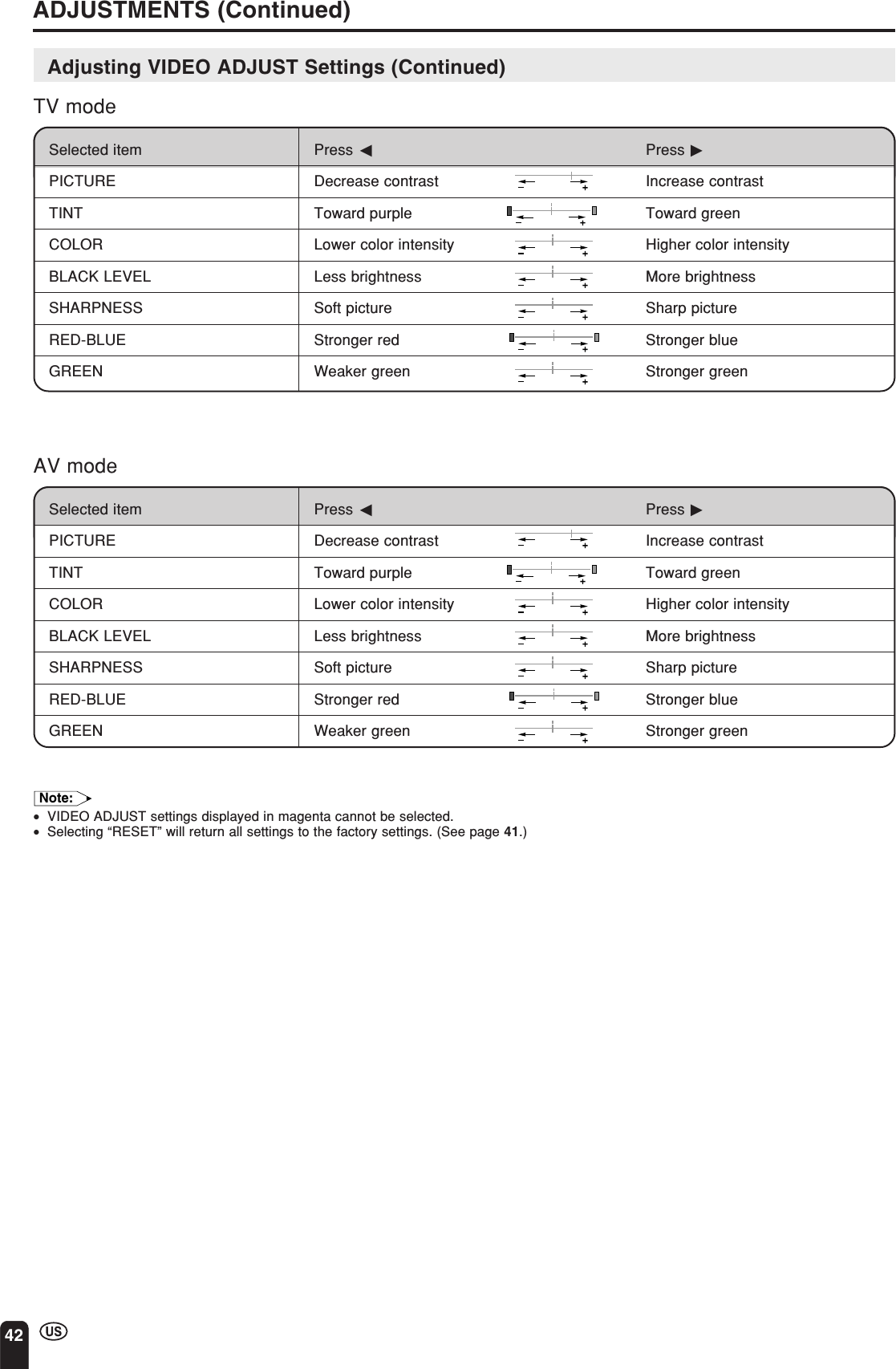
![ENGLISH41ADJUSTMENTS (Continued)EXIT:RETURNP I CTURE50 –+ADJUST :SELECT :MENUPICTURE [ 50]TINTCOLORBLACK LEVELSHARPNESSSELECT : ENTER: EXIT:V I DEO ADJUST ( TV)RETURN[ 0][ 0][ 0][ 0]RED-BLUE [ 0]GREEN [ 0]RESETENTERMENUMENUSLEEP T IMERV IDEO ADJUSTPRESETCLOSED CAPT IONV–CHIP BLOCKSET UPSELECT : ENTER: EXIT:ENTERMENUMENUSLEEP T IMERV IDEO ADJUSTPRESETCLOSED CAPT IONV–CHIP BLOCKSET UPSELECT : ENTER: EXIT:ENTERMENUCHVOLPOWERENTERDISPLAYMUTESLEEP PIC. FLIPBRIGHT TV/VIDEO MENUFLASH-BACKENTER/a/b/c/dMENUAdjusting VIDEO ADJUST SettingsVideo adjustments have different selection items depending on TV mode or AVmode (signal from an external device). (See page 42.)1Press MENU to display the MENUscreen.2Press a/b to move the cursor to“VIDEO ADJUST”, and press ENTER.3Press a/b to move the cursor to thedesired item, and press ENTER.4Press c/d to change the setting.Note:•See page 42 for the settings.5Press MENU to return to the mainscreen.](https://usermanual.wiki/Sharp/TCG041/User-Guide-395152-Page-42.png)
![ENGLISH43ADJUSTMENTS (Continued)SET UP■EZ SETUPWhen you move to an area with different broadcasting signals, the set willautomatically memorize the channel number and time. Refer to pages 22 and23 for more information on EZ SETUP.■SETTING THE AIR/CABLEIt is necessary to set the receiving mode to AIR or CABLE channels to receivelocally broadcast TV programs.1Switch the screen to TV mode and pressMENU to display the MENU screen.2Press a/b to move the cursor to“SET UP”, and press ENTER.3Press a/b to move the cursor to“CH-SETTING”, and press ENTER.•When the screen is not in TV mode,“CH-SETTING” is displayed in magentaand not available.4Press c/d to move the cursor to“AIR/CABLE”, and press ENTER.5Press c/d to move the cursor to thedesired mode, and press ENTER.6Press MENU to return to the mainscreen.•Receivable channels of your TV set are:AIR channels: CABLE channels:VHF: 2 through 13 1 (HRC and IRC)UHF: 14 through 69 2 through 125 (STD, HRC and IRC)CHVOLPOWERENTERDISPLAYMUTESLEEP PIC. FLIPBRIGHT TV/VIDEO MENUFLASH-BACKENTER/a/b/c/dMENUCH–SETT INGAI R/CABLEEZ SETUPCH SEARCHCH MEMORYSELECT : ENTER: EXIT:RETURNENTERMENUAIR/CABLESELECT : EXIT:AIRCABLEMENUENTER:RETURNENTERMENUSLEEP T IMERV IDEO ADJUSTPRESETCLOSED CAPT IONV–CHIP BLOCKSET UPSELECT : ENTER: EXIT:ENTERMENUBLUE SCREEN [OFF]LANGUAGESELECT : EXIT:ENTERRETURN SET UPCH–SETT I NGENTER:MENUCLOCK](https://usermanual.wiki/Sharp/TCG041/User-Guide-395152-Page-44.png)
![44ADJUSTMENTS (Continued)CHVOLPOWERENTERDISPLAYMUTESLEEP PIC. FLIPBRIGHT TV/VIDEO MENUFLASH-BACKENTER/a/b/c/dMENUCH–SETT INGAI R/CABLECH SEARCHCH MEMORYRETURNEZ SETUPSTART: EXIT:CH SEARCHAIR 2MENUMENUSLEEP T IMERV IDEO ADJUSTPRESETCLOSED CAPT IONV–CHIP BLOCKSET UPBLUE SCREEN [OFF]LANGUAGERETURN SET UPCH–SETT I NGCLOCKPress dto add channel 2to the TV memoryPress cto erase channel 2from the TV memoryCH–SETT INGAI R/CABLECH SEARCHCH MEMORYRETURNEZ SETUPTO ADD: EXIT:CH MEMORYAIR 2MENUTO ERASE : EXIT:CH MEMORYAIR 2MENUCHVOLPOWERENTERDISPLAYMUTESLEEP PIC. FLIPBRIGHT TV/VIDEO MENUFLASH-BACKENTER/a/b/c/dChannelSelectMENUSET UP (Continued)■Saving broadcast TV channels in the memory1Press MENU to display the MENUscreen, press a/b to move the cursorto “SET UP”, and press ENTER.2Press a/b to move the cursor to“CH-SETTING”, and press ENTER.3Press a/b to move the cursor to“CH SEARCH”, and press ENTER.4Press d. The tuner will search throughall available channels in your area andadd them to the TV memory.•To interrupt CH SEARCH, press c. CHSEARCH will stop at the current channeland will not add any higher channels.5Press MENU to exit.■Adding weak or additional channels or erasing unwanted channels fromTV memory1Press MENU to display the MENUscreen, press a/b to move the cursorto “SET UP”, and press ENTER.2Press a/b to move the cursor to“CH-SETTING”, and press ENTER.3Press a/b to move the cursor to“CH MEMORY”, and press ENTER.4Use a/b or Channel Select to selecteach desired channel to add or erase.5Press d to add the channel to the TVmemory or press c to erase thechannel from the TV memory.6Press MENU to exit.•If CH SEARCH is performed again, thepreviously memorized channels will be lost.](https://usermanual.wiki/Sharp/TCG041/User-Guide-395152-Page-45.png)
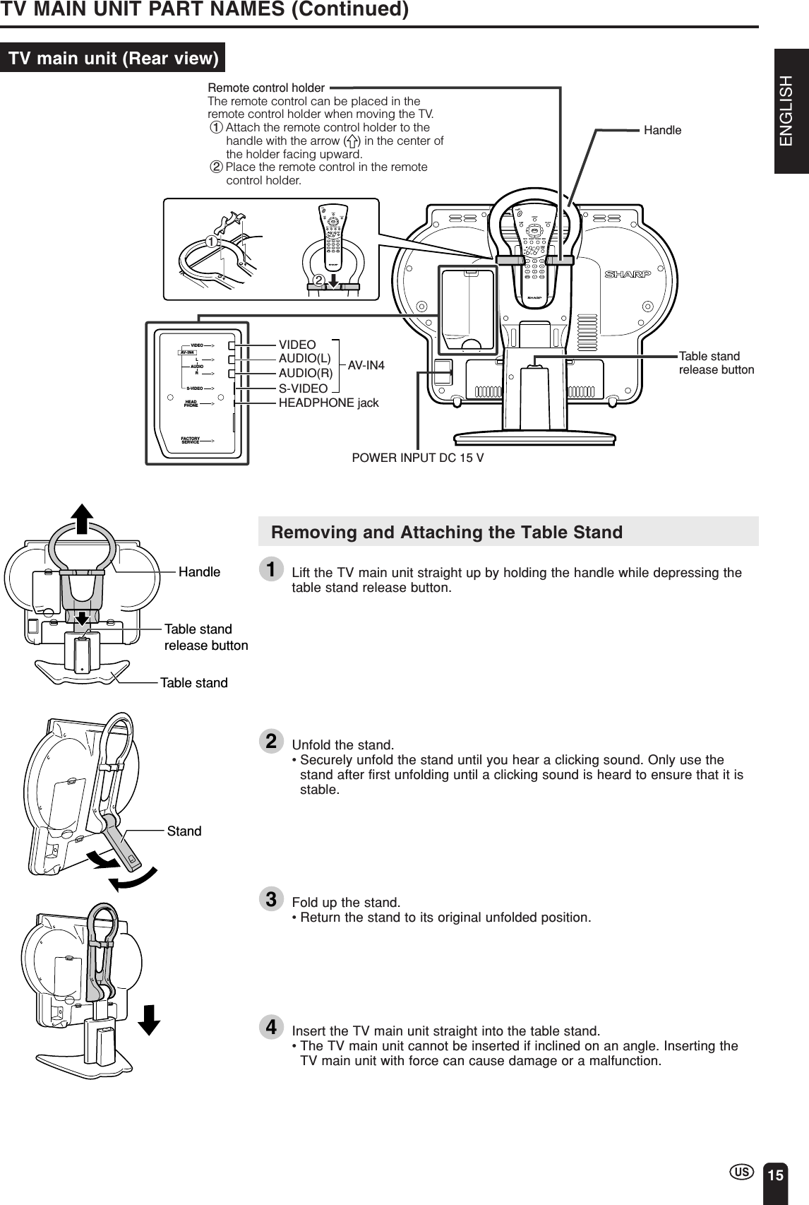
![ENGLISH45ADJUSTMENTS (Continued)CHVOLPOWERENTERDISPLAYMUTESLEEP PIC. FLIPBRIGHT TV/VIDEO MENUFLASH-BACKENTER/a/b/c/dMENUMENUSLEEP T IMERV IDEO ADJUSTPRESETCLOSED CAPT IONV–CHIP BLOCKSET UPSELECT : ENTER: EXIT:ENTERMENUBLUE SCREEN [OFF]LANGUAGESELECT : EXIT:ENTERRETURN SET UPCH–SETT I NGENTER:MENUCLOCKBLUE SCREEN [ O N ]LANGUAGESELECT : EXIT:ENTERRETURN SET UPCH–SETT I NGENTER:MENUCLOCKAdjusting BLUE SCREEN Settings■BLUE SCREENThis function automatically turns the screen blue if no broadcast signal isreceived.1Press MENU to display the MENUscreen.2Press a/b to move the cursor to“SET UP”, and press ENTER.3Press a/b to move the cursor to“BLUE SCREEN”, and press ENTER.4Press c/d to select “ON” or “OFF”, andpress ENTER.5Press MENU to return to the mainscreen.Note:•When received signals are weak or interfered with by some other signals, the BLUESCREEN function may be activated. To watch the TV under such conditions, set“BLUE SCREEN” to “OFF”.•The BLUE SCREEN function is activated when AV1, AV2, AV3 or AV4 input mode isselected with no signal being input.](https://usermanual.wiki/Sharp/TCG041/User-Guide-395152-Page-46.png)
![46ADJUSTMENTS (Continued)CC/TEXT [OFF]SELECT : EXIT:RETURN CLOSED CAPT IONENTER:ENTERMENUCC/TEXT [CC1]EXIT:RETURN CLOSED CAPT IONENTER:ENTERADJUST :MENUMENUSLEEP T IMERV IDEO ADJUSTPRESETCLOSED CAPT IONV–CHIP BLOCKSET UPSELECT : ENTER: EXIT:ENTERMENUCHVOLPOWERENTERDISPLAYMUTESLEEP PIC. FLIPBRIGHT TV/VIDEO MENUFLASH-BACKENTER/a/b/c/dMUTEMENUAdjusting CLOSED CAPTION Settings■SETTING CLOSED CAPTION•This TV set is equipped with an internal ClosedCaption decoder. “CLOSED CAPTION” is asystem which allows conversations, narration, andsound effects in TV programs and home videos tobe viewed as captions on the TV screen (see theillustration).•Not all programs and videos will offer closedcaptioning. Please look for the “” symbol toensure that captions will be shown.•The Closed Caption broadcasts can be viewed in two modes: CAPTION andTEXT. For each mode, two channels are available: CH1 and CH2.The CAPTION mode shows subscripts of dialogs and commentaries of TVdramas and news programs while allowing a clear view of the picture.The TEXT mode displays various information over the picture (such as TVprogram schedules and weather forecasts, etc.) that is independent of the TVprograms.Setting the CLOSED CAPTION on theMENU screen1Press MENU to display the MENUscreen.2Press a/b to move the cursor to“CLOSED CAPTION” , and pressENTER.3Press ENTER for the CLOSEDCAPTION setting.4Press c/d to change the CLOSEDCAPTION setting, and press ENTER.CC1 CC2OFF T1 T2Note:•CC1: CAPTION mode for CH1 dataCC2: CAPTION mode for CH2 dataT1: TEXT mode for CH1 dataT2: TEXT mode for CH2 data5Press MENU to return to the mainscreen.Note:•Color characters for closed captioning are notsupported with this TV. Characters are white only.•If a broadcast contains Closed Caption data andMUTE is pressed, the TV set enters CAPTIONmode automatically. Pressing MUTE again willreturn the TV set to its previous condition.•Closed Caption may malfunction (white blocks,strange characters, etc.) if signal conditions arepoor or if there are problems at the broadcastsource. This does not necessarily indicate aproblem with your TV set.•If any button is pressed to call up the On-ScreenDisplay while viewing a Closed Caption broad-cast, the closed captions will disappear momen-tarily.•If no TEXT broadcast is being received whileviewing in the TEXT mode, the screen maybecome dark and blank for some programs.Should this occur, switch the CLOSED CAPTIONmode to “OFF”.](https://usermanual.wiki/Sharp/TCG041/User-Guide-395152-Page-47.png)
![ENGLISH47ADJUSTMENTS (Continued)Adjusting V-CHIP Settings■V-CHIP•This function allows TV programs to be restricted and TV usage to becontrolled based on FCC data. It prevents children from watching violent orsexual scenes that may be harmful.•Restriction of TV programs includes two ratings that contain information aboutthe program: the MPAA rating and the TV Parental Guidelines. The MPAArating is restricted by age. TV Parental Guidelines are restricted by age andcontent.•Since a TV program may use either the MPAA rating or the TV Guidelines,both should be adjusted for complete control.[1] MPAA RATINGRATING DescriptionG GENERAL AUDIENCES. All ages admitted.PG PARENTAL GUIDANCE SUGGESTED. Some material may not be suitablefor children.PG-13 PARENTS STRONGLY CAUTIONED. Some material may beinappropriate for children under 13.R RESTRICTED. Under 17 requires accompanying parent or adult guardian.NC-17 NO ONE 17 AND UNDER ADMITTED.X X is an older rating that is unified with NC-17 but may be encoded in thedata of older movies.:MPAA RATINGExample 1:When PG-13 in the age-based rating isblocked, this will also automatically blockthe higher ratings R, NC-17 and X.Example 2:When R in the age-based rating isblocked, this will also automatically blockthe higher ratings NC-17 and X.Note:•The MPAA rating is only age-based.⇑agebased⇓](https://usermanual.wiki/Sharp/TCG041/User-Guide-395152-Page-48.png)
![48ADJUSTMENTS (Continued)⇐ content based ⇒FV V S L D(Fantasy (Violence) (Sexual (Adult (SexuallyViolence) Situation) Language) SuggestiveDialog)TV-Y (All children)TV-Y7 (Direct to Older ✕Children)TV-G (General XAudience)TV-PG (Parental ✕✕✕✕Guidance Suggested) xxxTV-14 (Parents ✕✕✕✕Strongly Cautioned) XTV-MA (Mature X✕✕✕ Audience Only)RATING⇑agebased⇓ Adjusting V-CHIP Settings (Continued)[2] TV PARENTAL GUIDELINES: The content rating can be set, but this rating is not normally broadcast by TV stations.✕: The content rating can be set.TV PARENTAL GUIDELINESExample 1:When TV-Y7 in the age-based rating is set to “BLOCK”, this will automatically block the higherratings: TV-G, TV-PG, TV-14 and TV-MA. In addition, D, L, S, V and FV in CONTENT areautomatically blocked unless you manually set “BLOCK CONTENT”.Example 2:When no item in the age-based rating is blocked, D in the content-based rating will be automaticallyblocked.Note:•Age-based ratings can be modified by the content-based ratings, but only in the combina-tions indicated by an X in the table above.•Choosing a lower age-based rating blocks the higher age-based ratings regardless ofcontent rating settings.•If you set “TV-Y” and “TV-Y7” to “BLOCK”, CONTENT will display all items.](https://usermanual.wiki/Sharp/TCG041/User-Guide-395152-Page-49.png)
![ENGLISH49ADJUSTMENTS (Continued)INPUT SECRET NO.– – – –EXIT:MENUMPAATV GUIDELINESSTATUSSELECT : EXIT:RETURN V–CHIP BLOCK[OFF]ENTER:ENTERMENUMPAAG [ –––––]EXIT:RETURNPG [ BLOCK ]PG–13 [BLOCK]R [BLOCK]NC–17 [ BLOCK]X [BLOCK]ENTER:ENTERADJUST :MENUMPAAG [ –––––]EXIT:RETURNPG [ –––––]PG–13 [–––––]R [ –––––]NC–17 [ –––––]X [ –––––]ENTER:ENTERSELECT :MENUENTER/a/b/c/dChannelSelectCHVOLPOWERENTERDISPLAYMUTESLEEP PIC. FLIPBRIGHT TV/VIDEO MENUFLASH-BACKMENUMENUSLEEP T IMERV IDEO ADJUSTPRESETCLOSED CAPT IONV–CHIP BLOCKSET UPSELECT : ENTER: EXIT:ENTERMENUAdjusting V-CHIP Settings (Continued)■SETTING V-CHIP[1] MPAA RATING1Press MENU to display the MENUscreen.2Press a/b to move the cursor to“V-CHIP BLOCK”, and press ENTER.3“INPUT SECRET NO.” will be displayed.Input the 4-digit secret number by usingChannel Select, and press ENTER.Note:•When you input the secret number for thefirst time, press ENTER to register.Otherwise, continue to step 4.4Press a/b to move the cursor to“MPAA”, and press ENTER.5Press a/b to move the cursor to “PG”,and press ENTER.6Press c/d to select “BLOCK”, andpress ENTER. If you set “PG” to“BLOCK”, “PG-13”, “R”, “NC-17” and “X”are automatically blocked.7Press MENU to return to the mainscreen.Note:•If you set “G” to “BLOCK”, all ratings are automatically blocked.•If you set “X” to “BLOCK”, “G”, “PG”, “PG-13”, “R” and “NC-17” are not blocked.](https://usermanual.wiki/Sharp/TCG041/User-Guide-395152-Page-50.png)
![50ADJUSTMENTS (Continued)CHVOLPOWERENTERDISPLAYMUTESLEEP PIC. FLIPBRIGHT TV/VIDEO MENUFLASH-BACKENTER/a/b/c/dMENUMPAATV GUIDELINESSTATUSSELECT : EXIT:RETURN V–CHIP BLOCK[OFF]ENTER:ENTERMENUTV GUIDEL INESTV–Y [ –––––]EXIT:BLOCK CONTENT[D L S V FV ]RETURNTV–Y7 [BLOCK ]TV–G [BLOCK ]TV–PG [BLOCK]TV–14 [BLOCK]TV–MA [BLOCK]ENTER:ENTERADJUST :MENUTV GUIDEL INESTV–Y [ –––––]SELECT : EXIT:BLOCK CONTENT[ ]RETURNTV–Y7 [–––––]TV–G [ –––––]TV–PG [–––––]TV–14 [–––––]TV–MA [ –––––]ENTER:ENTERMENUAdjusting V-CHIP Settings (Continued)[2] TV GUIDELINES● Setting TV GUIDELINES1Repeat steps 1 to 3 of [1] MPAARATING. (See page 49.)2Press a/b to move the cursor to“TV GUIDELINES”, and press ENTER.3Press a/b to move the cursor to“TV-Y7”, and press ENTER.4Press c/d to select “BLOCK”, andpress ENTER. If you set “TV-Y7” to“BLOCK”, “TV-G”, “TV-PG”, “TV-14” and“TV-MA” are automatically blocked. Inaddition, “D”, “L”, “S”, “V” and “FV” inCONTENT are automatically blocked.5Press MENU to return to the mainscreen.](https://usermanual.wiki/Sharp/TCG041/User-Guide-395152-Page-51.png)
![ENGLISH51ADJUSTMENTS (Continued)CHVOLPOWERENTERDISPLAYMUTESLEEP PIC. FLIPBRIGHT TV/VIDEO MENUFLASH-BACKENTER/a/b/c/dMENUTV GUIDEL INESTV–Y [ –––––]SELECT : EXIT:BLOCK CONTENT[ ]RETURNTV–Y7 [–––––]TV–G [ –––––]TV–PG [–––––]TV–14 [–––––]TV–MA [ –––––]ENTER:ENTERMENUD [ –––––]EXIT:RETURNL [ BLOCK ]S [ –––––]V [ –––––]FV [–––––]BLOCK CONTENTENTER:ENTERADJUST :MENUMPAATV GUIDELINESSTATUSSELECT : EXIT:RETURN V–CHIP BLOCK[OFF]ENTER:ENTERMENUD [ –––––]SELECT : EXIT:RETURNL [ –––––]S [ –––––]V [ –––––]FV [–––––]BLOCK CONTENTENTER:ENTERMENUAdjusting V-CHIP Settings (Continued)■Setting BLOCK CONTENT1Repeat steps 1 to 3 of [1] MPAARATING. (See page 49.)2Press a/b to move the cursor to“TV GUIDELINES”, and press ENTER.3Press a/b to move the cursor to“BLOCK CONTENT”, and press ENTER.4Press a/b to move the cursor to thedesired item, and press ENTER.5Press c/d to select “BLOCK” or “-----”(unblock), and press ENTER.6Press MENU to return to the mainscreen.Note:•If you set “TV-14” to “BLOCK”, “TV-MA” is automatically blocked. Contents “D”, “L”, “S” and“V” are automatically blocked by X in the table on page 48.](https://usermanual.wiki/Sharp/TCG041/User-Guide-395152-Page-52.png)
![52ADJUSTMENTS (Continued)CHVOLPOWERENTERDISPLAYMUTESLEEP PIC. FLIPBRIGHT TV/VIDEO MENUFLASH-BACKENTER/a/b/c/dMENUMPAATV GUIDELINESSTATUSENTER: EXIT:RETURN V–CHIP BLOCK[ON ]ENTER:ENTERMENUADJUST :MPAATV GUIDELINESSTATUSSELECT : EXIT:RETURN V–CHIP BLOCK[OFF]ENTER:ENTERMENUV–CHIP HAS BEEN ACT IVATEDTV–YINPUT SECRET NO.– – – –EXIT:MENUCHVOLPOWERENTERDISPLAYMUTESLEEP PIC. FLIPBRIGHT TV/VIDEO MENUFLASH-BACKMENUChannelSelectAdjusting V-CHIP Settings (Continued)[3] ACTIVATING V-CHIP BLOCK● Setting STATUSYou can activate V-CHIP BLOCK after setting [1] MPAA RATING and/or [2]TV GUIDELINES.1Repeat steps 1 to 3 of [1] MPAARATING. (See page 49.)2Press a/b to move the cursor to“STATUS”, and press ENTER.3Press c/d to set “STATUS” to “ON”,and press ENTER.Note:•If “STATUS” is set to “OFF”, “V-CHIPBLOCK” will not be activated.4Press MENU to return to the mainscreen.[4] CANCELING THE V-CHIP BLOCK SCREEN WHILE V-CHIP BLOCK ISACTIVATED1“V-CHIP HAS BEEN ACTIVATED”appears if you watch a program with thesame Program Rating data youconfigured.Note:•“V-CHIP HAS BEEN ACTIVATED” will notbe displayed if “STATUS” is not configuredto “ON”.•Since the V-CHIP setting is performedusing wireless communication, in order tobe sure that this setting is performedcorrectly, perform it with the WirelessCenter nearby so that you can confirm thevideo signal is correctly received.2Press MENU to display “INPUTSECRET NO.”3Input the 4-digit secret number by usingChannel Select; V-CHIP BLOCK istemporarily canceled. If you input anincorrect secret number, “SECRET NO.IS INCORRECT” is displayed. In thiscase, input the correct secret number.Note:•If you turn the power on from off, V-CHIP BLOCK will be activated again.•If you select “V-CHIP BLOCK” again by using MENU, V-CHIP BLOCK will be turned onagain.•Usually when there are no problems with the reception, the V-CHIP information is indicatedin yellow characters against a blue background, but when the reception conditions areunstable, the background and the characters may not always be indicated correctly incolor. (The background may consist of a 7-color striped image while the characters aredisplayed in white.)Should such a case occur, even when pressing the “MENU” button on the remote control,the “INPUT SECRET NO.” screen is not displayed, making it impossible to input a secretnumber. Therefore, perform this operation only after first receiving normal motion pictureon the screen.](https://usermanual.wiki/Sharp/TCG041/User-Guide-395152-Page-53.png)
![ENGLISH53ADJUSTMENTS (Continued)CHVOLPOWERENTERDISPLAYMUTESLEEP PIC. FLIPBRIGHT TV/VIDEO MENUFLASH-BACKINPUT SECRET NO.– – – –EXIT:MENUINPUT SECRET NO.* * * *EXIT:MENUChannelSelectCHVOL MENU-+VOL (+)CH ( )MENUAdjusting V-CHIP Settings (Continued)[5] CHANGING V-CHIP BLOCK SETTINGS1Repeat steps 1 to 2 of [1] MPAARATING, then “INPUT SECRET NO.”will be displayed.2Input the 4-digit secret number by usingChannel Select; the V-CHIP selectmode will be displayed. Set V-CHIPBLOCK again.[6] CHANGING OR CLEARING THE SECRET NUMBERIf you forget the secret number, clear the secret number as follows.1Repeat steps 1 to 2 of [1] MPAARATING, or 1 to 2 of [4] CANCELINGTHE V-CHIP BLOCK SCREEN WHILEV-CHIP BLOCK IS ACTIVATED, then“INPUT SECRET NO.” will be displayed.2Press and hold both CH ( ) and VOL(+) on the TV set simultaneously untilthe message “INPUT SECRET NO.”blinks.3Press MENU to exit.Upper control panelof the TV main unit](https://usermanual.wiki/Sharp/TCG041/User-Guide-395152-Page-54.png)