Sharp TCG041 Monitor User Manual LC 15L1U 001 013 p65
Sharp Corporation Monitor LC 15L1U 001 013 p65
Sharp >
manual
LC-15L1U
LIQUID CRYSTAL TELEVISION
TÉLÉVISEUR ACL
TELEVISOR CON PANTALLA
DE CRISTAL LÍQUIDO
TELEVISOR DE CRISTAL
LÍQUIDO
LC-15L1U
OPERATION MANUAL
MODE D’EMPLOI
MANUAL DE OPERACIÓN
MANUAL DE OPERAÇÃO
ENGLISH
FRANÇAIS
ESPAÑOL
PORTUGUÊS
SHARP ELECTRONICS CORPORATION
Sharp Plaza, Mahwah, New Jersey 07430-2135
SHARP CORPORATION
Printed on 100% post-consumer recycled paper.
Imprimé sur 100% de papier recyclé.
Impreso en 100% de papel reciclado de postconsumo.
Papel 100% Reciclado-Cuidado do Meio Ambiente.
Printed in Japan
Imprimé au Japon
Impreso en Japón
Impresso no Japão
TINS-B124WJZZ
04P02-###
ENGLISH
1
LC-15L1U
LIQUID CRYSTAL TELEVISION
OPERATION MANUAL
ENGLISH
IMPORTANT INFORMATION
WARNING: TO REDUCE THE RISK OF FIRE OR ELECTRIC SHOCK, DO NOT EXPOSE
THIS PRODUCT TO RAIN OR MOISTURE.
CAUTION
RISK OF ELECTRIC SHOCK
DO NOT OPEN
CAUTION: TO REDUCE THE RISK OF ELECTRIC SHOCK,
DO NOT REMOVE COVER (OR BACK).
NO USER-SERVICEABLE PARTS INSIDE.
REFER SERVICING TO QUALIFIED SERVICE
PERSONNEL.
The lightning flash with arrowhead symbol, within an
equilateral triangle, is intended to alert the user to
the presence of uninsulated “dangerous voltage”
within the product’s enclosure that may be of
sufficient magnitude to constitute a risk of electric
shock to persons.
The exclamation point within a triangle is intended to
alert the user to the presence of important operating
and maintenance (servicing) instructions in the
literature accompanying the product.
IMPORTANT:
To aid reporting in case of loss or theft, please record the TV’s model
and serial numbers in the space provided. The numbers are located at
the rear of the TV.
U.S.A. ONLY
Model No.:
Serial No.:
2
CANADA ONLY
IMPORTANT INFORMATION (Continued)
WARNING: FCC Regulations state that any unauthorized changes or modifications to this equipment not expressly
approved by the manufacturer could void the user’s authority to operate this equipment.
“Note to CATV system installer: This reminder is provided to call the CATV system installer’s attention to Article 820-40 of the National Electrical
Code that provides guidelines for proper grounding and, in particular, specifies that the cable ground shall be connected to the grounding
system of the building, as close to the point of cable entry as practical.”
CAUTION: TO PREVENT ELECTRIC SHOCK, MATCH WIDE BLADE OF PLUG TO WIDE
SLOT, FULLY INSERT.
This product utilizes tin-lead solder, and fluorescent lamp containing a small amount of mercury. Disposal of these
materials may be regulated due to environmental considerations. For disposal or recycling information, please contact
your local authorities or the Electronic Industries Alliance: www.eia.org
Note: This equipment has been tested and found to comply with the limits for a Class B digital device, pursuant to part 15
of the FCC Rules. These limits are designed to provide reasonable protection against harmful interference in a residential
installation. This equipment generates, uses and can radiate radio frequency energy and, if not installed and used in
accordance with the operation manual, may cause harmful interference to radio communications. However, there is no
guarantee that interference will not occur in a particular installation. If this equipment does cause harmful interference to
radio or television reception, which can be determined by turning the equipment off and on, the user is encouraged to try
to correct the interference by one or more of the following measures:
•Reorient or relocate the receiving antenna.
•Increase the separation between the equipment and receiver.
•Connect the equipment into an outlet on a circuit different from that to which the receiver is connected.
•Consult the dealer or an experienced radio/TV technician for help.
U.S.A. ONLY
To prevent radio interference to the licensed service, this device is intended to be operated indoors and away from
windows to provide maximum shielding. Equipment (or its transmit antenna) that is installed outdoors is subject to
licensing.
Operation is subject to the following two conditions: (1) this device may not cause interference, and (2) this device must
accept any interference, including interference that may cause undesired operation of the device.
U.S.A. ONLY
U.S.A. ONLY
CANADA ONLY

ENGLISH
3
CONTENTS
Page
IMPORTANT INFORMATION................................... 1
DEAR SHARP CUSTOMER ..................................... 4
IMPORTANT SAFETY PRECAUTIONS .................. 4
REGARDING BATTERY CARE ............................... 7
CORRECT USE OF THE PRODUCT ....................... 9
SUPPLIED ACCESSORIES ................................... 10
PREPARATION....................................................... 11
TV MAIN UNIT PART NAMES ............................... 14
WIRELESS CENTER PART NAMES ..................... 17
REMOTE CONTROL .............................................. 18
OPERATION FOR TRANSMISSION
AND RECEPTION OF VIDEO
AND AUDIO SIGNALS ....................................... 19
POWER ................................................................... 20
Turning the Main Power on and off .................. 20
Viewing with a Home AC Wall Outlet ............... 21
EZ SETUP (WITH AUTO CLOCK SETTING) ........ 22
EZ Setup during the First Power On ................ 22
SETTING THE CLOCK ........................................... 24
AUTO CLOCK Setting ....................................... 24
MANUAL CLOCK Setting.................................. 26
TV SIGNALS IN YOUR REGION ........................... 27
BATTERY CHARGE AND TRANSMISSION
SETTING .............................................................. 28
Battery Charge .................................................. 28
Transmission Setting ......................................... 28
BASIC OPERATION ............................................... 31
Turning on Power .............................................. 31
Standby.............................................................. 31
Switching TV/VIDEO [AV1/AV2/AV3/AV4]
Modes ............................................................. 32
Sound Volume ................................................... 33
Changing Channels ........................................... 34
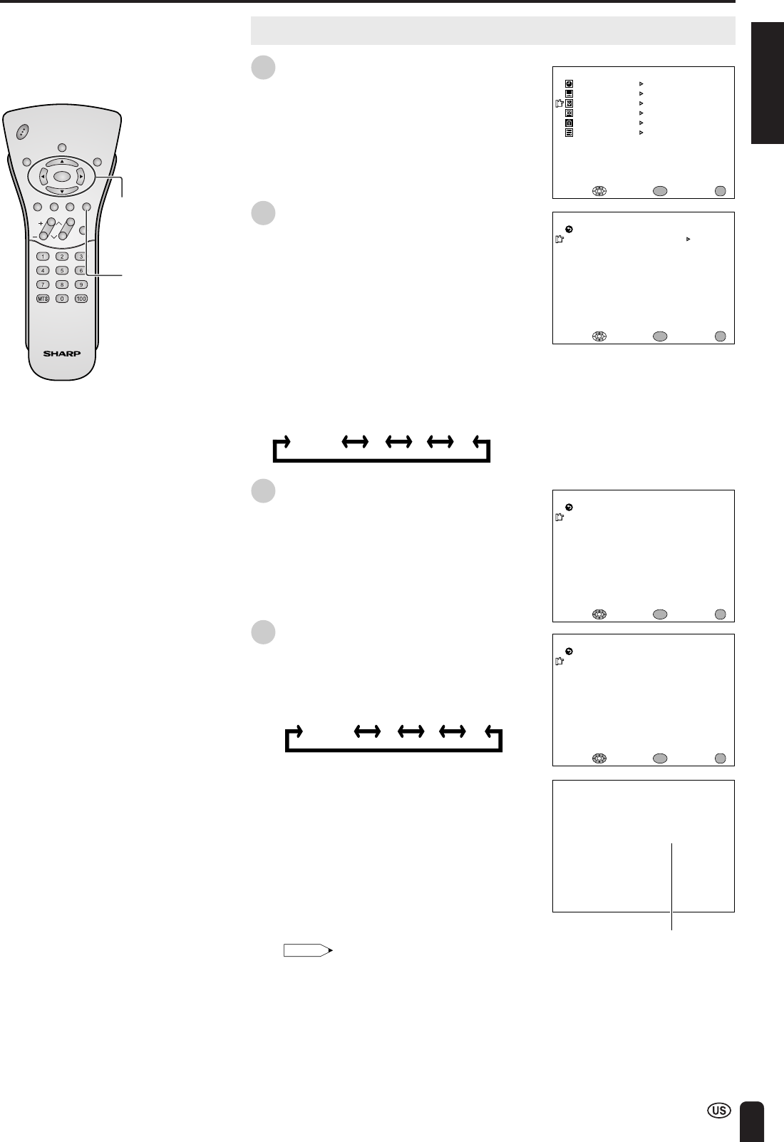
SELECTING MENU ITEMS .................................... 35
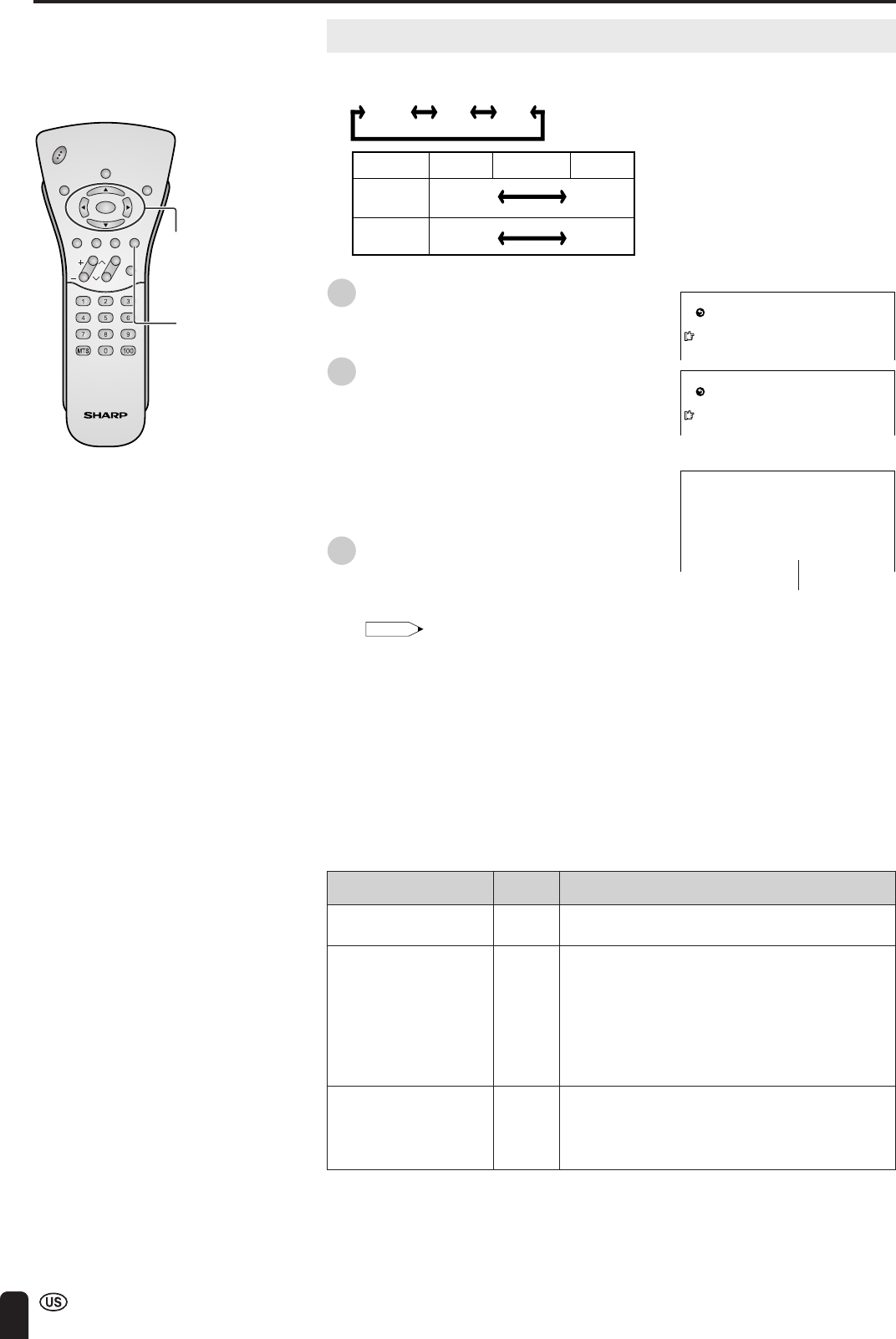
ADJUSTMENTS ...................................................... 36
Adjusting SLEEP TIMER Settings .................... 36
Adjusting BRIGHTNESS Settings ..................... 37
Adjusting PICTURE FLIP Settings.................... 38
Adjusting PRESET Settings .............................. 39
Adjusting LANGUAGE Settings ........................ 40
Adjusting VIDEO ADJUST Settings .................. 41
SET UP .............................................................. 43
Adjusting BLUE SCREEN Settings................... 45
Adjusting CLOSED CAPTION Settings ............ 46
Adjusting V-CHIP Settings ................................ 47
CONNECTION SYSTEM WITH VARIOUS WAYS
OF BEING USED ................................................. 54
Examples of Various Uses ................................ 54
Connecting System Chart of LC-15L1U ........... 55
Method of Connecting External Equipment ...... 56
Method of Using the Video Controller .............. 57
Watching Played Back Image from External
Equipment....................................................... 58
Connecting a Home Video Game System, etc.
(AV-IN4) .......................................................... 59
How to Use AV-IN1 Output ............................... 60
Monitor Output for Picture and Sound Output
from AV-IN2/OUT Terminal ............................ 61
TROUBLESHOOTING ............................................ 62
SPECIFICATIONS................................................... 65
DIMENSIONAL DRAWINGS .................................. 66
CALLING FOR SERVICE ....................................... 67
LIMITED WARRANTY ............................................ 67
Page

4
DEAR SHARP CUSTOMER
Thank you for your purchase of the Sharp Liquid Crystal Television. To ensure safety and many years
of trouble-free operation of your product, please read the Important Safety Precautions carefully before
using this product.
IMPORTANT SAFETY PRECAUTIONS
Electricity is used to perform many useful functions, but it can also cause personal injuries and property damage if
improperly handled. This product has been engineered and manufactured with the highest priority on safety. However,
improper use can result in electric shock and/or fire. In order to prevent potential danger, please observe the following
instructions when installing, operating and cleaning the product. To ensure your safety and prolong the service life of your
LCD color TV product, please read the following precautions carefully before using the product.
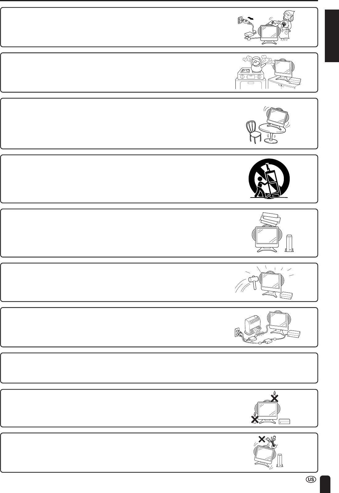
■Read instructions—All operating instructions must be read and understood before the product is operated.
■Keep this manual in a safe place—These safety and operating instructions must be kept in a safe place for future
reference.
■Observe warnings—All warnings on the product and in the instructions must be observed closely.
■Follow instructions—All operating instructions must be followed.
■Attachments—Do not use attachments not recommended by the manufacturer. Use of inadequate attachments
can result in accidents.
■Power source—This product must operate on a power source specified on the specification label. If you are not
sure of the type of power supply used in your home, consult your dealer or local power company. For units
designed to operate on batteries or another power source, refer to the operating instructions.
■Power cord protection—The power cords must be routed properly to prevent people from stepping on them or
objects from resting on them. Check the cords at the plugs and product.
■If the AC adapter is misplaced or needs to be replaced, obtain the same type of adapter from a SHARP service
center or your dealer.
■Overloading—Do not overload AC outlets or extension cords.
Overloading can cause fire or electric shock.
■Entering of objects and liquids—Never insert an object into the product through vents or openings. High voltage
flows in the product, and inserting an object can cause electric shock and/or short internal parts. For the same
reason, do not spill water or liquid on the product.
■Servicing—Do not attempt to service the product yourself. Removing covers can expose you to high voltage and
other dangerous conditions. Request a qualified service person to perform servicing.
■Repair—If any of the following conditions occurs, unplug the power cord from the AC outlet, and request a quali-
fied service person to perform repairs.
a.When the power cord or plug is damaged.
b.When a liquid was spilled on the product or when objects have fallen into the product.
c.When the product has been exposed to rain or water.
d.When the product does not operate properly as described in the operating instructions.
Do not touch the controls other than those described in the operating instructions. Improper adjustment of
controls not described in the instructions can cause damage, which often requires extensive adjustment work by
a qualified technician.
e.When the product has been dropped or damaged.
f. When the product displays an abnormal condition. Any noticeable abnormality in the product indicates that the
product needs servicing.
■Replacement parts—In case the product needs replacement parts, make sure that the service person uses
replacement parts specified by the manufacturer, or those with the same characteristics and performance as the
original parts. Use of unauthorized parts can result in fire, electric shock and/or other danger.
■Safety checks—Upon completion of service or repair work, request the service technician to perform safety checks
to ensure that the product is in proper operating condition.
■Wall or ceiling mounting—When mounting the product on a wall or ceiling, be sure to install the product according
to the method recommended by the manufacturer.
■Polarization—This AC adapter may be equipped with a polarized alternating current line plug (a plug having one
blade wider than the other). This plug will fit into the power outlet only one way. This is a safety feature. If you are
unable to insert the plug fully into the outlet, try reversing the plug. If the plug should still fail to fit, contact your
electrician to replace your obsolete outlet.
Do not defeat the safety purpose of the polarized plug.
ENGLISH
5
IMPORTANT SAFETY PRECAUTIONS (Continued)
■The Liquid Crystal panel is a very high technology product with 921,600 thin film transistors, giving you fine picture
details.
Occasionally, a few non-active pixels may appear on the screen as a fixed point of blue, green or red.
Please note that this does not affect the performance of your product.
■Cleaning—Unplug the power cord from the AC outlet before cleaning the prod-
uct. Use a damp cloth to clean the product. Do not use liquid cleaners or aerosol
cleaners.
■Water and moisture—Do not use the product near water, such as bathtub,
washbasin, kitchen sink and laundry tub, swimming pool and in a wet basement.
■Stand—Do not place the product on an unstable cart, stand, tripod or table.
Placing the product on an unstable base can cause the product to fall, resulting
in serious personal injuries as well as damage to the product. Use only a cart,
stand, tripod, bracket or table recommended by the manufacturer or sold with the
product. When mounting the product on a wall, be sure to follow the manufactur-
er’s instructions. Use only the mounting hardware recommended by the manu-
facturer.
■When relocating the product placed on a cart, it must be moved with utmost
care. Sudden stops, excessive force and uneven floor surface can cause the
product to fall from the cart.
■Ventilation—The vents and other openings in the cabinet are designed for
ventilation. Do not cover or block these vents and openings since insufficient
ventilation can cause overheating and/or shorten the life of the product. Do not
place the product on a bed, sofa, rug or other similar surface, since they can
block ventilation openings. This product is not designed for built-in installation; do
not place the product in an enclosed place such as a bookcase or rack, unless
proper ventilation is provided or the manufacturer’s instructions are followed.
■The Liquid Crystal panel used in this product is made of glass. Therefore, it can
break when the product is dropped or applied with impact. Be careful not to be
injured by broken glass pieces in case the Liquid Crystal panel breaks.
■Heat sources—Keep the product away from heat sources such as radiators,
heaters, stoves and other heat-generating products (including amplifiers).
■To prevent fire, never place any type of candle or naked flames on the top or
near the TV set.
■To prevent fire or shock hazard, do not expose this products to dripping or
splashing. No objects filled with liquids, such as vases, should be placed on the
products.
6
IMPORTANT SAFETY PRECAUTIONS (Continued)
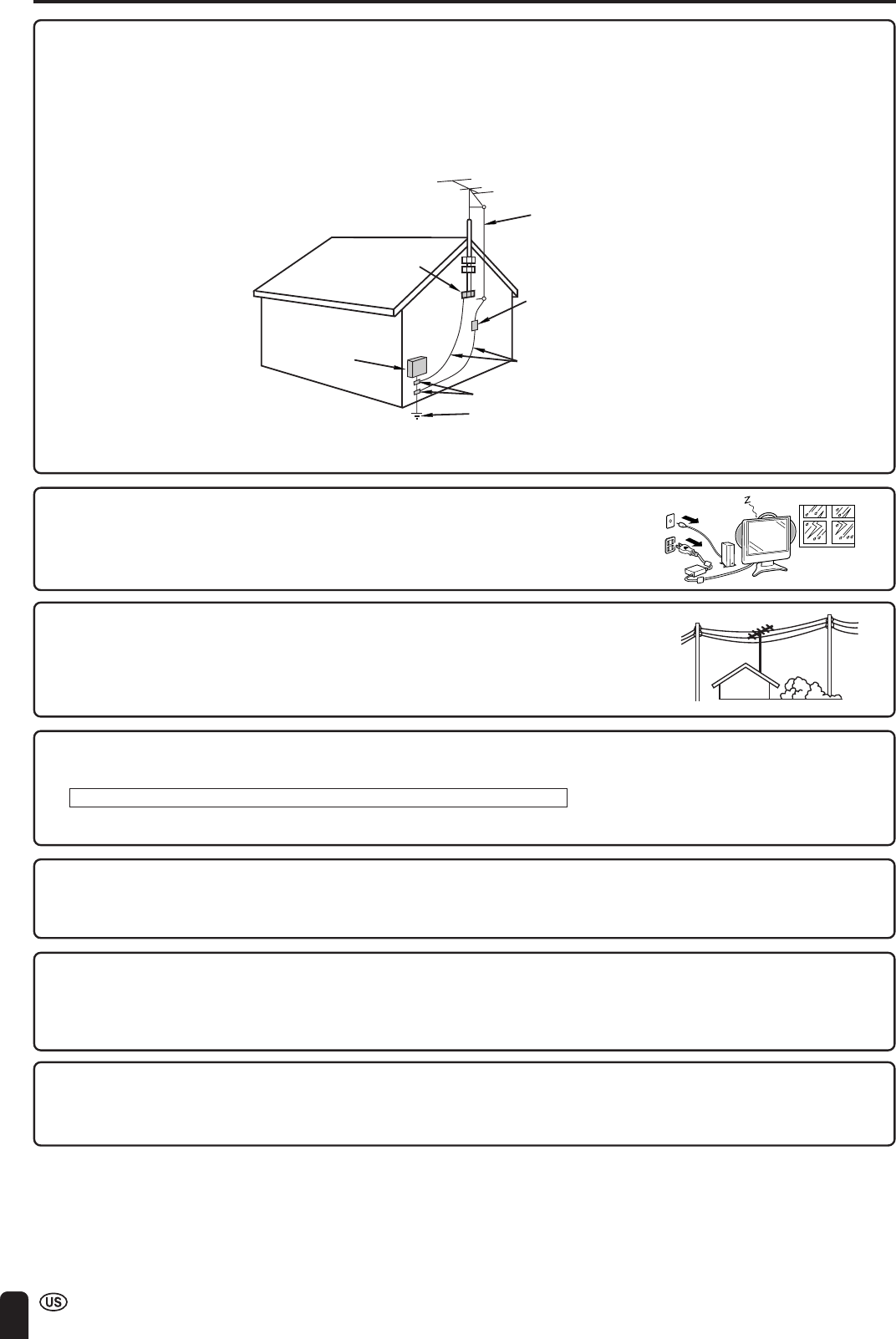
■If an outside antenna is connected to the television equipment, be sure the antenna system is grounded so as to
provide some protection against voltage surges and built-up static charges. Section 810 of the National Electrical
Code provides information with respect to proper grounding of the mast and supporting structure, grounding of the
lead-in wire to an antenna discharge unit, size of grounding conductors, location of antenna-discharge unit, connection
to grounding electrodes, and requirements for the grounding electrode.
ANTENNA
LEAD IN
WIRE
ANTENNA
DISCHARGE UNIT
(NEC SECTION 810-20)
GROUNDING CONDUCTORS
(NEC SECTION 810-21)
GROUND CLAMPS
POWER SERVICE GROUNDING
ELECTRODE SYSTEM
(NEC ART 250, PART H)
ELECTRIC
SERVICE
EQUIPMENT
NEC—NATIONAL ELECTRICAL CODE
GROUND
CLAMP
EXAMPLE OF ANTENNA GROUNDING AS PER
NATIONAL ELECTRICAL CODE
■Do not use in the direct vicinity of electronic appliances that use high-precision control signals or weak signals.
The use of this unit may have adverse effects including incorrect operation of electronic appliances posing the risk of
accidents.
Examples of electronic appliances for which you should exercise caution
Hearing aids, pace-makers, other medical electric appliances, fire alarms, automatic doors, other automatically
controlled devices, etc.
■Do not use in places where its use is forbidden, including inside aircraft and in hospitals.
The use of this unit may have adverse effects on electronic appliances and electric appliances for medical use, posing the
risk of accidents.
Observe the instructions of medical institutions.
■Although this unit is equipped with an anti-bugging scramble function, be aware of interception.
As this unit uses radio waves, keep in mind a third party may intentionally try to intercept the signals the unit emits.
Do not use this unit to dispatch important information that contains secrets or for information that may endanger human
life.
* Interception constitutes the intentional or accidental use of the contents of wireless communication by third parties.
■Concerning damages
Please be aware Sharp will not accept any claims for damage by you or a third party due to incorrect operation of this
unit, any troubles during use, or other problems, or any damages arising out of the use of this unit, except for those cases
for which Sharp is legally held liable for compensation.
■Power Lines – An outside antenna system should not be located in the vicinity of
overhead power lines or other electric light or power circuits, or where it can fall
into such power lines or circuits. When installing an outside antenna system,
extreme care should be taken to keep from touching such power lines or circuits
as contact with them might be fatal.
■Lighting – For added protection for this television equipment during a lightning
storm, or when it is left unattended and unused for long period of time, unplug it
from the wall outlet and disconnect the antenna. This will prevent damage to the
equipment due to lightning and power-line surges.
ENGLISH
7
REGARDING BATTERY CARE
•Charge the battery only at temperatures within the range of
50°F to 86°F (10°C to 30°C) (temperatures that are comfort-
able for people). At lower temperatures it becomes more
difficult to charge the battery and the battery deteriorates. It is
not possible to sufficiently charge the battery at high tempera-
tures.
• The battery may become hot during charging or during use,
but this is not a sign of malfunctioning.
• It may take more time to fully charge a hot battery.
Precautions to be Taken during Charging
Regarding Operating Time and Use under Low Temperatures for the Battery
•The battery has a certain life expectancy. The battery is
consumed as time elapses even if the battery is not used. A
battery that has been used for about a year may give you less
operating time depending on the conditions under which it
was stored. If a battery that has been charged correctly
operates for a much shorter time than usual, it has reached
the end of its life and must be replaced with a new battery.
•When the battery is at a low temperature (lower than 50°F
(10°C)) in winter, the operating time may be very short. The
battery undergoes an internal chemical reaction in order to
generate electricity. When the temperature outside is lower,
the chemical reaction becomes less vigorous and operating
time becomes shorter.
How to Get the Most out of the Battery
•Turn off the power supply frequently when not in use in order to give the battery longer life.
•The battery is consumed as time elapses even if the battery is
not used. To prevent consumption;
(1) If the battery will not be used for a long time, use the
product to run down what is left of the battery charge and
set “BATTERY CHARGE” to “OFF” in the menu screen.
(Refer to page 28.)
(2) Make sure to use the battery at least once every six
months.
Storage Precautions
Charge the battery before use.
Battery type lithium-ion battery
Nominal voltage 11.1 V
Battery capacity 5700 mAh
Operating temperature 50°F to 86°F (10°C to 30°C)
Maximum dimensions appx. Length 8 23/64 inch (212 mm) × Width 1 5/8 inch (41 mm) × Height 1 35/64 inch (39 mm)
Weight appx. 1.1 lbs. (0.5 kg)
•The battery used in the product is a lithium-ion battery. Even if
the battery is charged and stored, the amount of charge in the
battery will drop.
• Make sure to charge the battery until the CHARGE indicator
of the product goes off (fully charged). The operating time is
shortened when using a battery which has not been fully
charged. (For a detailed description of how to charge the
battery, refer to page 20.)
Battery Specification

8
REGARDING BATTERY CARE (Continued)
Prohibited use for which safety is not guaranteed.
•Do not try to disassemble or modify the battery. The battery
contains safety mechanisms and protection devices.
Damaging these safety devices may cause the battery to
generate heat or smoke, or to rupture or ignite.
•Do not connect the + and – terminals together with metal
such as wires. Do not carry or store the battery together
with metal objects such as necklaces and hairpins. Doing
so may cause the battery to be short-circuited so as to
cause an extremely large amount of electric current to flow,
which may cause the battery to generate heat or smoke,
rupture or ignite, or may cause metal objects such as wire,
necklaces, or hairpins to heat up.
•Do not expose batteries to fire or heat. Doing so may cause
insulating materials to melt, damage gas exhaust valves or
safety mechanisms, or ignite electrolytic solutions, which
may cause the battery to generate heat or smoke, rupture
or ignite.
•Do not leave the battery in or near fire, stoves, or other
high-temperature locations (of temperatures greater than
140°F (60°C)). If a resin separator is damaged by heat, the
battery may become internally short-circuited and this may
cause the battery to generate heat or smoke, rupture or
ignite.
•Do not expose the battery to water or salt water, or allow
the battery to get wet. If the protection device contained in
the battery is broken, this may cause the battery to gener-
ate heat or smoke, rupture or ignite.
•Do not charge the battery near a fire or in direct sunlight. If
the battery becomes hot, the protection device for prevent-
ing danger operates to disable the battery from being
charged. If the protection device contained in the battery
becomes broken, the battery is charged at an abnormal
electric current or voltage. An abnormal chemical reaction
occurs inside the battery which may cause the battery to
generate heat or smoke, rupture or ignite.
•Charge the battery in compliance with the specified charg-
ing conditions. If the battery is charged without compliance
to the charging conditions (at temperatures greater than the
specified temperature, at voltages and electric current
greater than the specified amount or with modified charg-
ers), the battery may be overcharged or charged at an
abnormal electric current and an abnormal chemical
reaction may occur inside the battery, which may cause the
battery to generate heat or smoke, rupture or ignite.
•Do not pierce the battery with nails, strike the battery with a
hammer, or step on the battery. Doing so may cause the
battery to generate heat or smoke, rupture or ignite.
•Do not subject the battery to strong impacts or throw it
away. If the protection device contained in the battery
becomes broken, the battery is charged at an abnormal
electric current or voltage. An abnormal chemical reaction
may then occur inside the battery, which may cause the
battery to generate heat or smoke, rupture or ignite.
•Do not use the battery if it has been considerably damaged
or deformed. This may cause the battery to generate heat
or smoke, rupture or ignite.
•Do not solder directly onto the battery. Doing so may cause
insulating materials to melt, or damage gas exhaust valves
or the safety mechanism, which may cause the battery to
generate heat or smoke, rupture or ignite.
•Use a battery case when carrying the battery.
•Keep the battery out of reach of children.
•In the event that the fluid inside the battery gets into one’s
eye, do not rub the eye because this may cause loss of
eyesight. Rinse the eye with clean water and consult a
doctor immediately. In the event that the fluid becomes
attached to skin or clothes, wash it off with clean water
immediately as this may cause injury.

ENGLISH
9
CORRECT USE OF THE PRODUCT
Precautions Regarding Radio Waves
■Do not use the product at the following locations. There may be cases where noise occurs or transmission/reception is
not possible.
•Locations where magnetic fields, electrostatic or interference occurs due to devices such as Bluetooth, wireless LANs, or
microwave ovens etc. that utilize the same frequency band (2.4 GHz) as the product. (There may be cases where radio waves
cannot reach depending on the environment.)
•Keep the product away from a radio devices during use. (There may be cases of noise interference.)
■Under the same frequency band as the product uses, in addition to Bluetooth, wireless LANs, and microwave ovens
etc. that utilize the same frequency band (2.4 GHz) as the product, operation can also take place at on-site radio
stations that require a license for mobile object identification used in factories and manufacturing lines etc. and
specified low power radio stations.
•Before using the product, make sure that there is no on-site radio stations for mobile object identification or specified low power
radio stations operating in the vicinity of the product.
•If there is any interference occurring to on-site radio stations for mobile object identification due to the product, stop using the
product immediately.
Regarding Range of Usage
■The product is limited to domestic use.
(There is a possibility that transmission distance may become short depending on the communication environment.)
■In the following cases, reception may become bad or impossible, which may cause sound and pictures to be inter-
rupted (pictures and sound are stopped), or blocks of noise to appear.
•Using the product in a reinforced concrete building such as a condominium building or a house of a metal structure.
•Using the product at locations near large-scale metallic furniture.
•Using the product in a crowd of people or close to buildings or obstacles, etc.
•Using the product at locations where magnetic fields, electrostatic and interference occur due to devices such as Bluetooth,
wireless LANs, or microwave ovens, etc. that utilize the same frequency band (2.4 GHz) as the product.
■Regarding reflected radio waves
•Radio waves that reach a television receiver are radio waves (direct waves) directly transmitted from a transmitter and radio
waves (reflected waves) arriving from various directions as a result of being reflected by walls, furniture, or buildings etc. There
are good and bad positions in terms of wave conditions due to the influence of these reflected waves, which may cause poor
picture reception. In this case, try changing the location of the TV receiver slightly. There are cases where pictures and sound
are distorted or interrupted due to the reflected waves as a result of a person passing over or approaching between the transmit-
ter and the television receiver.
When a signal other than a regular signal is input
•When a signal other than a regular signal that is incompatible with this unit is input, the screen may freeze, but this is not a
malfunction.
•When a signal other than a regular signal is input from the Antenna, AV-IN1, AV-IN2, or AV-IN3 terminals, reception may be bad
depending on the performance of the Wireless Center, and the message “THIS SIGNAL IS NOT COMPATIBLE.” will display.
•Signals compatible with the Wireless Center are as follows:
H: 15.73426 kHz / V: 59.94 Hz
(Note: Reception may be available with AV-IN4.)
Precaution Regarding Electromagnetic Wave Disturbance
•If electric devices, such as a cellular phone, are used near this unit, electromagnetic wave disturbance may occur between
apparatus. In such cases, the picture quality may decrease and noise may appear.
10
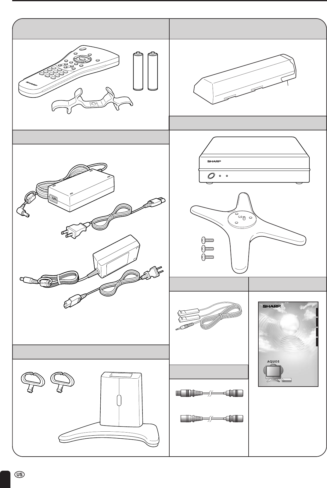
SUPPLIED ACCESSORIES
Confirm that the following accessories are provided with the product.
Wireless remote control (×1), Remote control holder (×1),
“AAA” size (UM/SUM-4) dry batteries (×2)
Wireless Center (×1), Wireless Center stand (×1)
Rechargeable battery (×1)
AC adapters (×2)
Cable clamps (×2), Table stand (×1)
*Product shape varies in some countries.
Screws (××
××
×3)
(See pages 11, 15, 18)
(See page 20)
(See pages 13, 21)
(See page 17)
(See page 59)
(See pages 55, 57, 60)
Terminal cover
SIGNAL LEVEL
MAIN
POWER
POWER
LIQUID CRYSTAL TELEVISION
TÉLÉVISEUR ACL
TELEVISOR CON PANTALLA
DE CRISTAL LÍQUIDO
TELEVISOR DE CRISTAL
LÍQUIDO
LC-15L1U
OPERATION MANUAL
MODE D’EMPLOI
MANUAL DE OPERACIÓN
MANUAL DE OPERAÇÃO
ENGLISHFRANÇAISESPAÑOLPORTUGUÊS
Manuals
Video controller (×1)
(See page 12)
Antenna cables (×2)
RRMCGA152WJSA
LHLDZA216WJZZ
UBAT1A011WJZZ
GDAI-A074WJSA
TINS-B124WJZZ
QCNWGA033WJPZ
QCNWG0003CEPA
Connecting System Chart of
LC-15L1U
TCAUZA072WJZZ
Registration Card
TCADEA028WJZZ
Cautions Regarding Radio
Wave Interference
TCAUZA071WJZZ
LHLDW0109CESA
(See page 15) CDAI-A072WJ02
QACCDA023WJPA × 2 pcs
UADP-A042WJPZ
UADP-A041WJPZ
QCNWG0004CEZZ
ENGLISH
11
PREPARATION
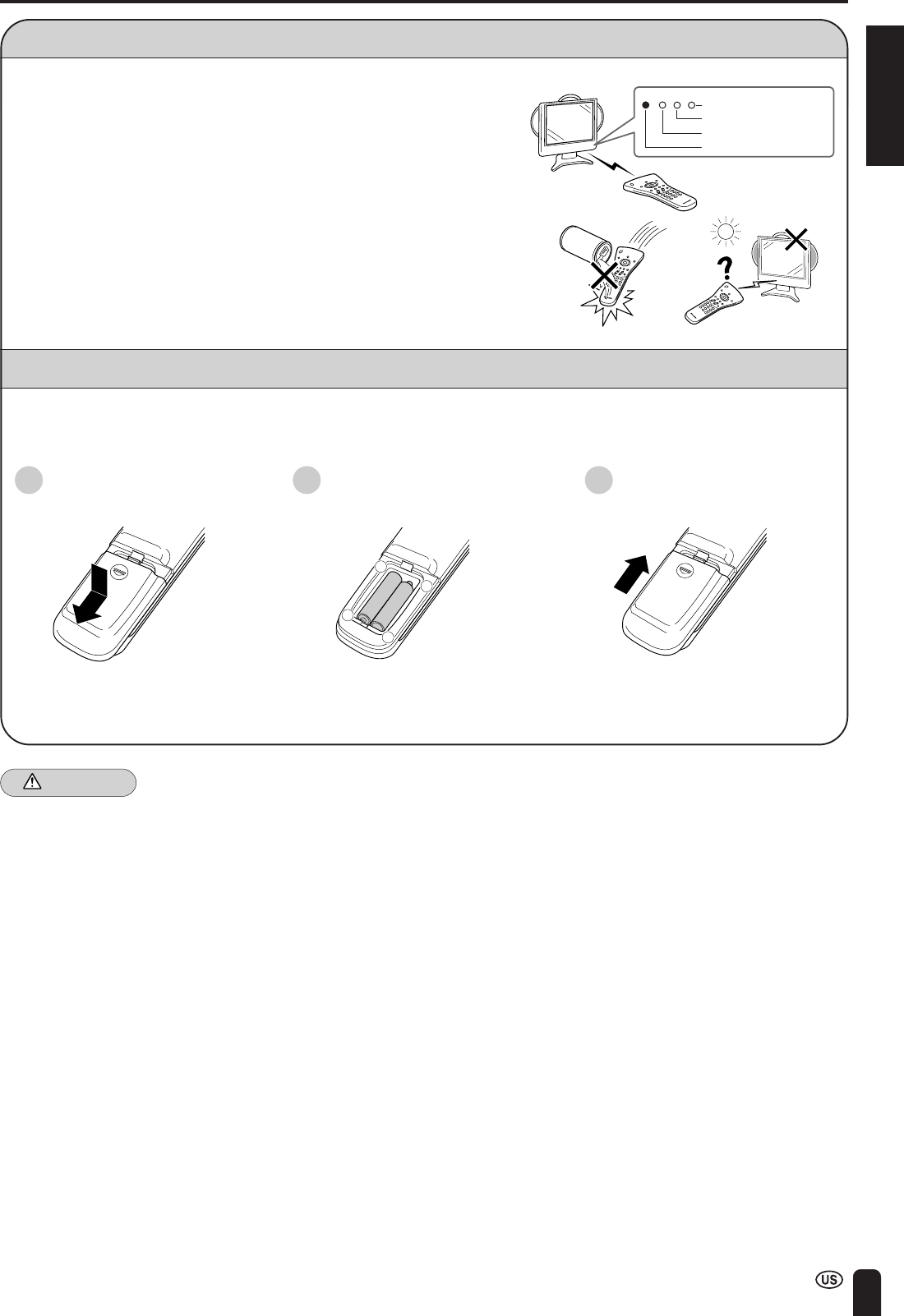
Using the Remote Control
■Use the remote control by pointing it toward the remote control sensor window
on the TV main unit. Objects between the remote control and sensor window
may prevent proper operation.
Cautions regarding use of the remote control
■Do not expose the remote control to shock.
In addition, do not expose the remote control to liquid, and do not place it in an
area with high humidity.
■Do not install or place the remote control under direct sunlight. The heat may
cause deformation of the unit.
■The remote control may not work properly if the remote control sensor window
of the TV main unit is under direct sunlight or strong lighting. In such cases,
change the angle of the lighting or LCD TV set, or operate the remote control
closer to the remote control sensor window.
Batteries for the Remote Control
Before using the LCD TV set for the first time, install two (“AAA” size, UM/SUM-4) batteries (supplied). When the batter-
ies become depleted and the remote control fails to operate, replace the batteries with new (“AAA” size, UM/SUM-4)
batteries.
1Open the battery cover.
■Slide the cover while pressing the
(b) part.
2Insert two (“AAA” size, UM/SUM-
4) batteries.
+
–
+
–
■Position the positive and negative
ends of the batteries as indicated in
the compartment.
Caution!
Cautions regarding batteries
Improper use of batteries can result in chemical leakage and/or explosion. Be sure to follow the instructions below.
•Place batteries with their terminals corresponding to the (+) and (–) as indicated in the compartment.
•Different types of batteries have different characteristics. Do not mix batteries of different types.
•Do not mix old and new batteries. Mixing old and new batteries can shorten the life of new battery and/or cause the old
battery to leak chemicals.
•Remove batteries when they become weak.
Chemicals that leak from batteries can cause a rash. If chemical leakage is found, wipe with a cloth.
•The batteries supplied with the product may have a shorter life expectancy due to storage conditions.
•If the remote control will not be used for an extended period of time, remove the batteries from the remote control.
SLEEP indicator
CHARGE indicator
POWER indicator
Remote sensor window
CHARGE SLEEPPOWER
3Close the battery cover.
■Engage the claw on the cover into
the battery housing and slide shut.
12
F-type connector
75-ohm coaxial cable
Antenna Connection
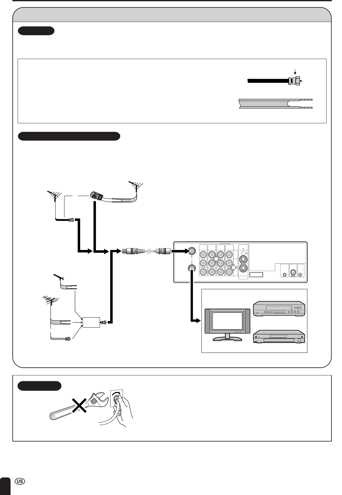
PREPARATION (Continued)
OUTDOOR ANTENNA CONNECTION
•Use one of the following two diagrams if you connect an outdoor antenna.
A: Using a VHF/UHF combination outdoor antenna
B: Using separate VHF and/or UHF outdoor antennas
•Connect the outdoor antenna cable lead-in to ANT. (Antenna terminal) on the rear of the Wireless Center.
F-type connector
75-ohm coaxial cable (round)
300-ohm twin-lead cable (flat)
1. A 75-ohm system is generally a round cable with F-type connector that can easily be
attached to a terminal without tools (not supplied).
2. A 300-ohm system is a flat “twin-lead” cable that can be attached to a 75-ohm terminal
through a 300-75-ohm adapter (not supplied).
ANTENNAS
•The antenna requirements for good color television reception are more important than those for black & white television reception.
For this reason, a good quality outdoor antenna is strongly recommended.
The following is a brief explanation of the type of connections that are provided with the various antenna systems.
NOTICE F-type connector should be finger-tightened only.
When connecting the RF cable to the TV set, do not tighten F-type
connector with tools.
If tools are used, it may cause damage to your TV set.
(The breaking of internal circuit, etc.)
Wireless Center
IN
OUT
AV-IN1AV-IN1AV-IN3
IR
OUT POWER
INPUT
DC12V
FACTORY
SERVICE
S-VIDEO
MONITOR
OUT
MONITOR
OUT
VIDEO
AUDIO
L
AUDIO
R
AV-IN2
/OUT
ANT.
TV/VCR/DVD, etc.
TV
VCR
DVD
75-ohm
coaxial cable
Antenna cable
300-ohm
twin-lead
VHF/UHF
antenna
VHF/UHF
antenna
300/75-ohm
adapter
(not supplied)
300-ohm
twin-lead
300-ohm
twin-lead
75-ohm
coaxial cable
OUTIN
VHF
antenna
UHF
antenna
Combiner
(not supplied)
or
or
B: Separate VHF and/or UHF antennas
A: Combination VHF/UHF antenna
ENGLISH
13
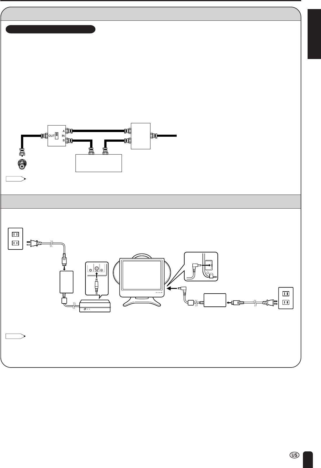
Antenna Connection (Continued)
PREPARATION (Continued)
Cable TV converter/
descrambler
(not supplied)
Two-set
signal
splitter
(not
supplied)
Cable TV line
RF switch (not supplied)
OUT IN
•A 75-ohm coaxial cable connector is built into the set for easy hookup. When connecting the 75-ohm coaxial cable to the
set, screw the 75-ohm cable to the ANT. terminal.
•Some cable TV companies offer “premium pay channels”. Since the signals of these premium pay channels are scram-
bled, a cable TV converter/descrambler is generally provided to the subscriber by the cable TV company. This converter/
descrambler is necessary for normal viewing of the scrambled channels. (Set your TV to channel 3 or 4, typically one of
these channels is used. If this is unknown, consult your cable TV company.) For more specific instructions on installing
cable TV, consult your cable TV company. One possible method of utilizing the converter/descrambler provided by your
cable TV company is explained below.
Please note: An RF switch provided with two inputs (A and B) is required (not supplied).
“A” position on the RF switch (not supplied): You can view all unscrambled channels by using the TV’s channel keys.
“B” position on the RF switch (not supplied): You can view the scrambled channels via the converter/descrambler by using
the converter’s channel keys.
CABLE TV (CATV) CONNECTION
Note:
•Consult your SHARP Dealer or Service Center for the type of splitter, RF switch or combiner that might be required.
Power Connection
Connect to the DC input terminal of each product.
Note:
•Always turn MAIN POWER of the TV main unit and the Wireless Center to OFF when connecting the AC adapters.
•If there is a Sharp product close to the video controller, the product may malfunction during transmission of the video controller.
•Unplug the AC adapters from the TV main unit, Wireless Center unit and AC wall outlet when the TV main unit is not to be used for a
long period of time.
AC wall
outlet
AC adapter AC cord
TV main unit
AC wall
outlet
AC adapter
AC cord
IR
OUT
POWER
INPUT
DC12V
FACTORY
SETTING
Wireless
Center
14
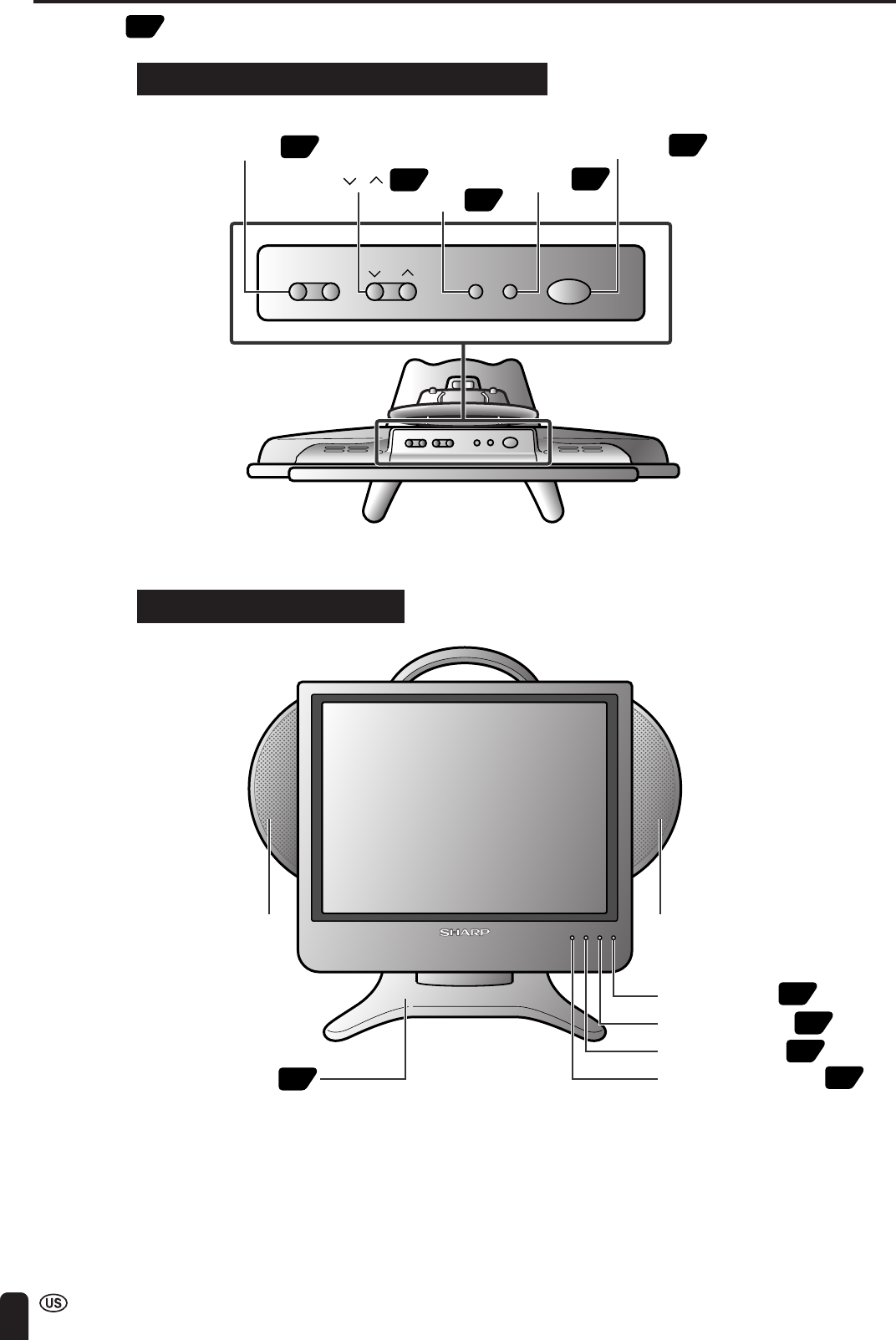
TV MAIN UNIT PART NAMES
Numbers in indicate the main pages where the corresponding item is described in this manual.
CHARGE indicator
POWER indicator
Remote sensor windowTable stand (Detachable)
Left speaker Right speaker
15
SLEEP indicator
36
20
22
11
TV main unit (Top view: Control section)
TV main unit (Front view)
CHVOL MENU TV/VIDEO MAIN POWER
-
+
VOL (–)/(+)
CH ( )/( )
MAIN POWER
TV/VIDEO
MENU
33
34
35
32
31
ENGLISH
15
TV MAIN UNIT PART NAMES (Continued)
TV main unit (Rear view)
AUDIO
AV- IN4
VIDEO
S-VIDEO
HEAD
PHONE
FACTORY
SERVICE
L
R
CHCH
ENTER
POWER
DISPLAY
SLEEP PIC. FLIP
MUTE
VOL
BRIGHT TV/VIDEO MENU
FLASH
BACK
MTS
POWER INPUT DC 15 V
HEADPHONE jack
S-VIDEO
VIDEO
AV-IN4
AUDIO(R)
AUDIO(L)
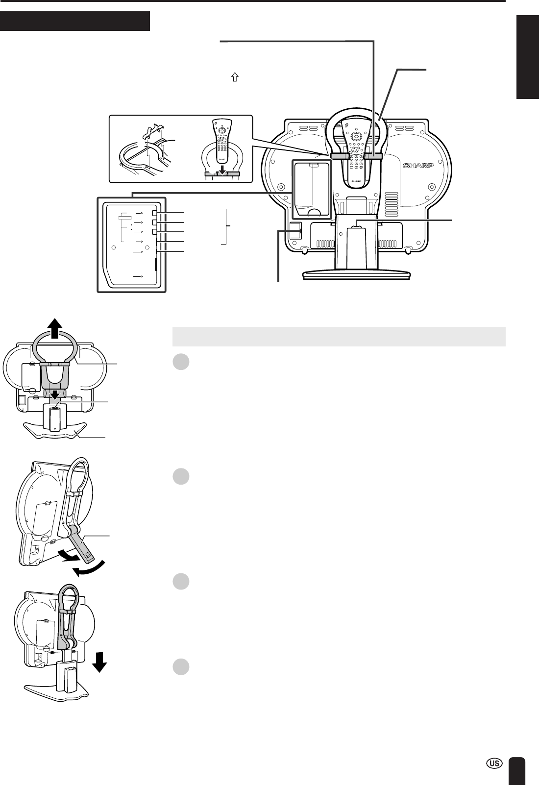
Remote control holder
The remote control can be placed in the
remote control holder when moving the TV.
1Attach the remote control holder to the
handle with the arrow ( ) in the center of
the holder facing upward.
2Place the remote control in the remote
control holder.
Table stand
release button
Handle
1
2
CHCH
ENTER
POWER
DISPLAY
SLEEP PIC. FLIP
MUTE
VOL
BRIGHT TV/VIDEO MENU
FLASH
BACK
MTS
Removing and Attaching the Table Stand
1Lift the TV main unit straight up by holding the handle while depressing the
table stand release button.
2Unfold the stand.
•Securely unfold the stand until you hear a clicking sound. Only use the
stand after first unfolding until a clicking sound is heard to ensure that it is
stable.
3Fold up the stand.
•Return the stand to its original unfolded position.
4Insert the TV main unit straight into the table stand.
•The TV main unit cannot be inserted if inclined on an angle. Inserting the
TV main unit with force can cause damage or a malfunction.
Stand
Handle
Table stand
release button
Table stand
16
TV MAIN UNIT PART NAMES (Continued)
Removing the Back Cover
■Before connecting cables and cords to the rear terminals, remove the back covers. Push
in the tabs and pull out the back covers carefully.
■To mount the cover, insert the 2 hooks on the bottom of the cover into the cabinet and
press on the upper part of the back cover until the tab locks in place with a click.
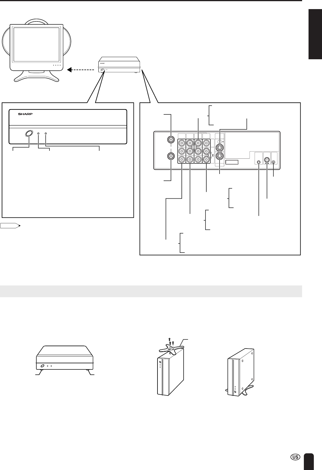
Listening with Headphones
■Plug the headphone mini-plug into the HEADPHONE jack located on the rear of the TV set.
Note:
•Headphones are not included in the supplied accessories.
•No sound is heard from the TV main unit speakers when a headphone mini-plug is connected into the HEADPHONE jack.
▼ On-screen display
Adjust the sound volume
using VOL (e)/(f) on the
remote control.
Headphones
AUDIO
AV- IN4
VIDEO
S-VIDEO
L
R
HEAD
PHONE
Rear terminal
20
VOLUME
ENGLISH
17
WIRELESS CENTER PART NAMES
SIGNAL LEVEL
MAIN
POWER
POWER
IN
OUT
AV-IN1AV-IN1AV-IN3
IR
OUT
POWER
INPUT
DC12V
FACTORY
SERVICE
S-VIDEO
MONITOR
OUT
MONITOR
OUT
VIDEO
AUDIO
L
AUDIO
R
AV-IN2
/OUT
ANT.
Transmission
SIGNAL LEVEL
indicator
(Reception gain)
· Green:
Communication
in progress
· Red:
Difficulty
in transmission
· Not lit:
Not communicating
POWER indicator
· Green:
Operation in
progress
(when power is on)
· Red: Standby
MAIN
POWER
button
Front
Antenna
input
terminal
Antenna
output
terminal
Rear
VIDEO
AUDIO (L)
AUDIO (R)
AV-IN1 (S-VIDEO)
MONITOR
OUT
MONITOR OUT
(S-VIDEO) Factory
adjustment
terminal
POWER INPUT
DC 12V
Video controller
terminal
VIDEO
AUDIO (L)
AUDIO (R)
AV-IN1
VIDEO
AUDIO (L)
AUDIO (R)
AV-IN3
VIDEO
AUDIO (L)
AUDIO (R)
AV-IN2
/OUT
Wireless Center
TV main unit
Wireless Center
stand
Rubber foot
Rubber foot
POWER Indicator
When the TV is turned off with the remote control, the
Wireless Center is switched to standby (POWER indicator
is lit red). (There may be a time lag of about 5 to 6
seconds.)
Placing the Wireless Center Where You Want It
We recommend placing the Wireless Center in an area
where there are no obstructions to impede radio wave
transmission/reception.
(Do not place the Wireless Center in a box.)
Note:
•The distance for which transmission is possible between the
TV main unit and Wireless Center is about 15 meters.
However, this distance may vary depending on the location
or conditions under which the Wireless Center is used.
•If the TV main unit gets close to the Wireless Center, there
may be cases where noise appears on the screen. In this
case, keep the TV main unit away from the Wireless Center
until the noise decreases, or try to change the transmission
channel setting (page 28).
Setting up the Wireless Center
•The Wireless Center can be placed horizontally or upright.
•When placing horizontally:
The side on which the rubber feet are attached is the
bottom.
•When placing upright:
Fasten the stand to the bottom of the Wireless Center with
the screws provided.
* Failure to securely fasten the stand may cause the
Wireless Center to tip over during use.
18
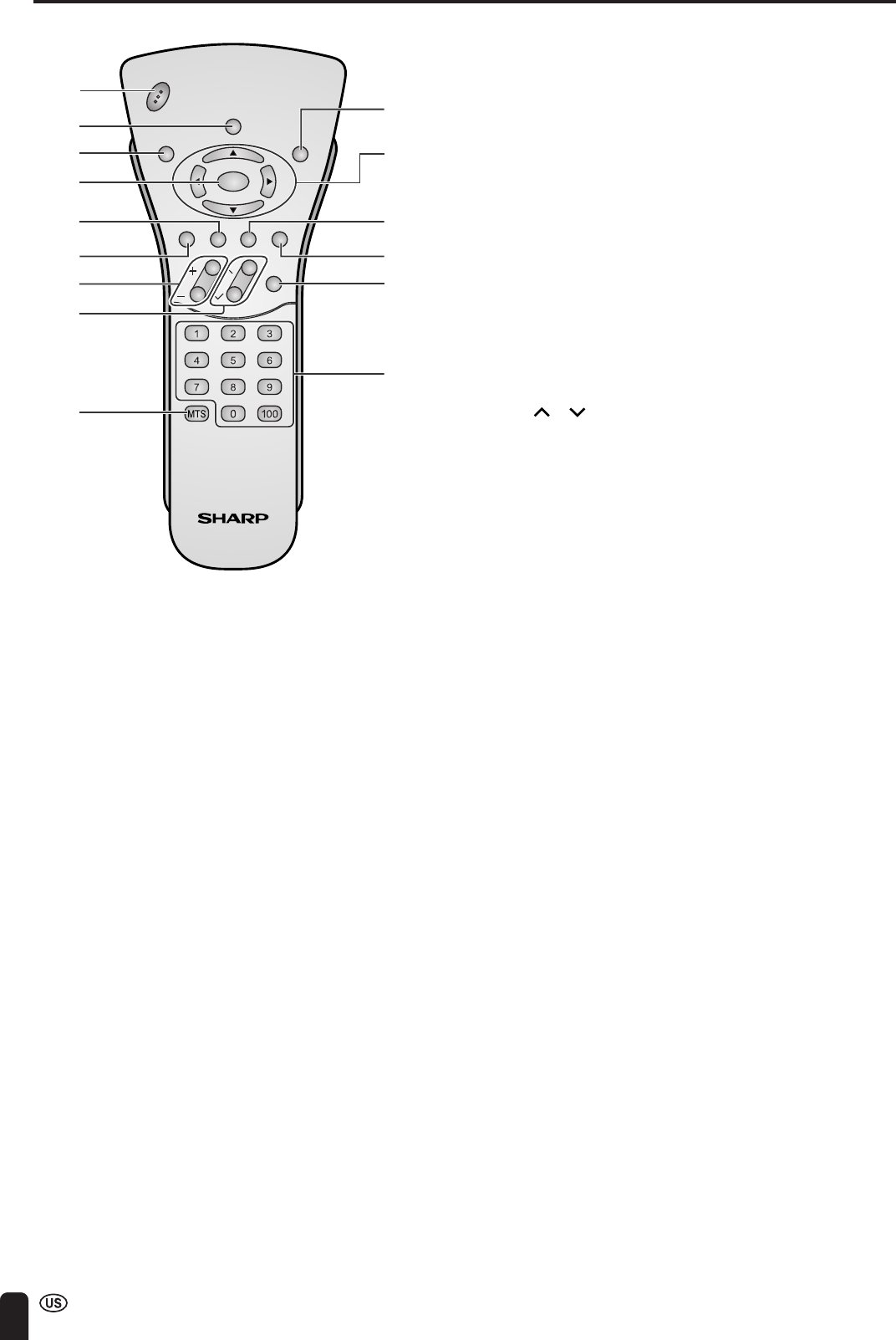
REMOTE CONTROL
CHVOL
POWER
ENTER
DISPLAY
MUTE
SLEEP PIC. FLIP
BRIGHT TV/VIDEO MENU
FLASH-
BACK
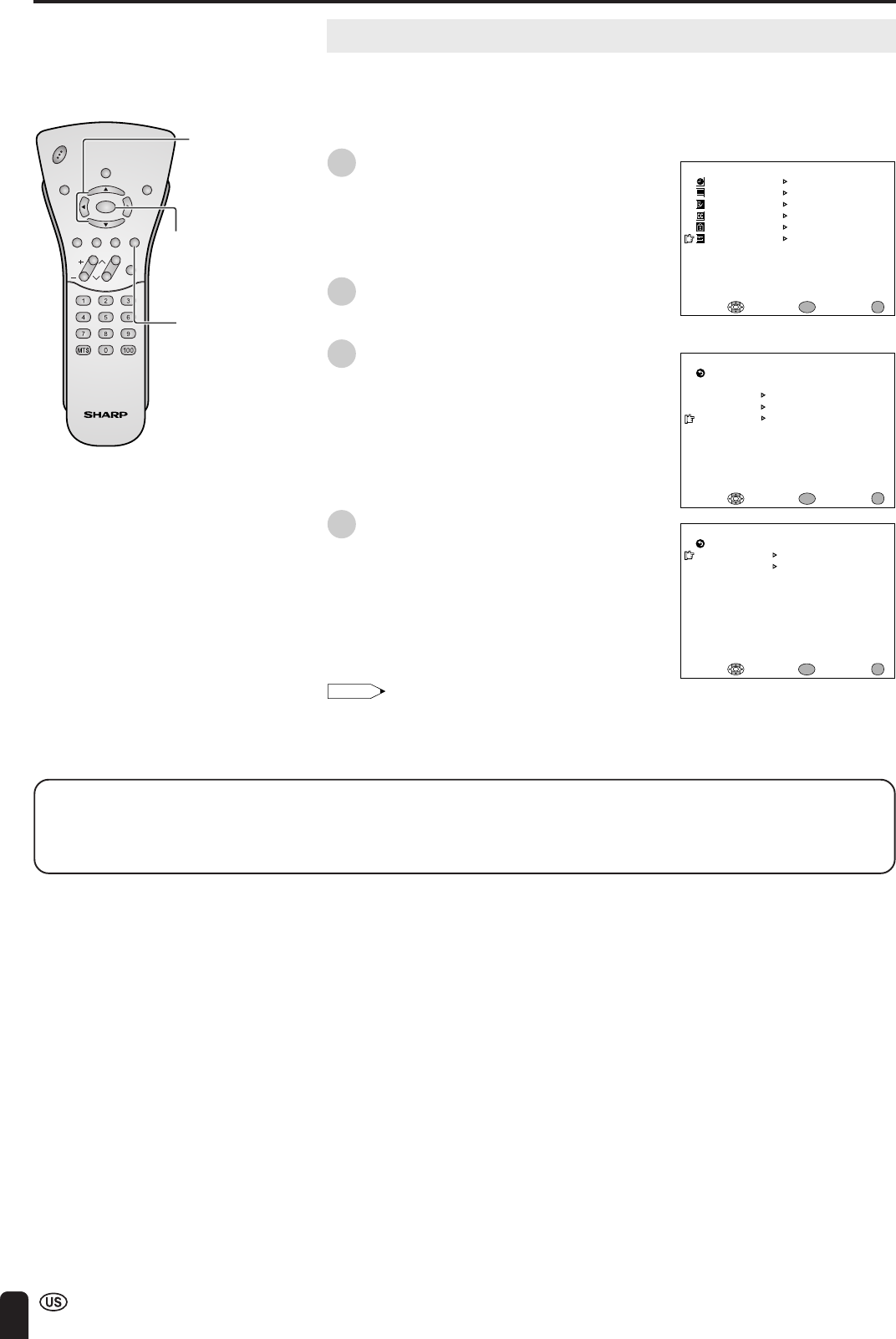
1 POWER (p. 22)
Switch the Liquid Crystal Television power on or off.
2 DISPLAY (p. 21)
Display the channel and time information, and check
the amount of remaining battery power.
3 SLEEP (p. 36)
Set the sleep timer.
4 ENTER
Execute a command.
5 BRIGHT (p. 37)
Adjust the brightness of the screen.
6 MUTE (p. 33)
Mute the sound.
7 VOL (+)/(–) (p. 33)
Set the volume.
8 CH ( )/( ) (p. 34)
Select channel.
9 MTS (p. 33)
Select audio settings.
10 PIC. FLIP (p. 38)
Set the orientation of the picture.
11 a/b/c/d (Cursor control) (p. 22)
Select a desired item on the screen.
12 TV/VIDEO (p. 32)
Select a Liquid Crystal Television input source.
13 MENU (p. 35)
Display the menu screen.
14 FLASHBACK (p. 34)
Return to the previous channel.
15 Channel Select (p. 34)
Set the channel.
1
2
3
4
5
6
7
8
9
10
11
12
13
14
15
ENGLISH
19
To confirm the TV main unit correctly receives the video and audio signal output by the Wireless Center, first put
these devices closely together.
OPERATION FOR TRANSMISSION AND RECEPTION OF VIDEO AND AUDIO SIGNALS
Preparation
1. Connecting an antenna to the Wireless Center .................................................................................. 12
2. Connecting an external equipment to the Wireless Center ............................................................... 55
3. Switching on the power of the Wireless Center.................................................................................. 22
4. Switching on the power of the TV main unit and the external equipment ....................................... 22
5. Performing “CH-SETTING”................................................................................................................... 43
6. Select a TV channel using the remote control and
confirm broadcast programs are received correctly ........................................................................... 34
7. Switching between TV/VIDEO using the remote control..................................................................... 32
8. Perform playback operations, etc. of the external equipment using the remote control to check
correct reception
(In case reception does not take place correctly, reconfirm the connections)
Check the video controller correctly points to the infrared receiver
of the remote control for the external equipment ...................................................................................... 57
9. Move the TV main unit to the desired location and check for correct reception
•Correct reception may not be possible in locations where radio waves cannot reach or when other
conditions exist that obstruct the radio waves.
In this case, change the location of the receiver to a place where it receives signals correctly.
•Since the “CHANNEL” of the “TRANSMISSION SETTING” is set to “AUTO”, the viewing conditions may
improve when the setting is reset.
Note:
•When watching TV with the built-in battery in the condition in which this unit was purchased, the battery does not have
enough charge left. Use after charging the battery sufficiently. (See page 20.)
•As this unit transmits and receives video and audio signals from the Wireless Center using radio waves, operation using
the remote control will be delayed by approximately 1 second.
Page
20
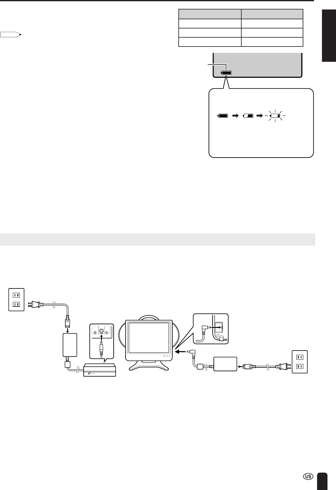
■Charging the Battery
Charge the battery when using for the first time (“BATTERY CHARGE” is set to “ON” (page 28)). Plug the AC adapter into a
wall outlet and the corresponding connector on the TV. The CHARGE indicator lights and charging begins. When charging is
completed, the CHARGE indicator turns off.
Note:
•General Reference for Charging Time:
When charging level has fallen to 0: About 5 hours
•General Reference for Battery Operating Time:
About 2 hours (when “BRIGHTNESS” is set to “NORMAL”)
* Operating time varies according to the conditions of use.
•Charging time refers to the amount of time required to charge a completely worn down battery.
•Charging time may be longer depending on ambient temperature, battery condition and other factors. Check to make sure the CHARGE
indicator is not lit before using.
•Operating time may be shorter depending on certain conditions such as use in cold climates.
Charging while Viewing:
The battery will be charged, while you are viewing if “BATTERY CHARGE” is set to “ON” (page 28). In this case, charging
takes about 12 hours. To preserve battery performance it is recommended that “BATTERY CHARGE” be set to “OFF” if
battery power is not in constant use.
Note:
•Charging time may be longer depending on ambient temperature, battery condition and other factors. Check to make sure the CHARGE
indicator is not lit before using.
AC adapter
TV main unit
CHARGE
indicator
AC wall outlet
AC cord
POWER
Turning the Main Power on and off
See page 15 for how to remove the table stand.
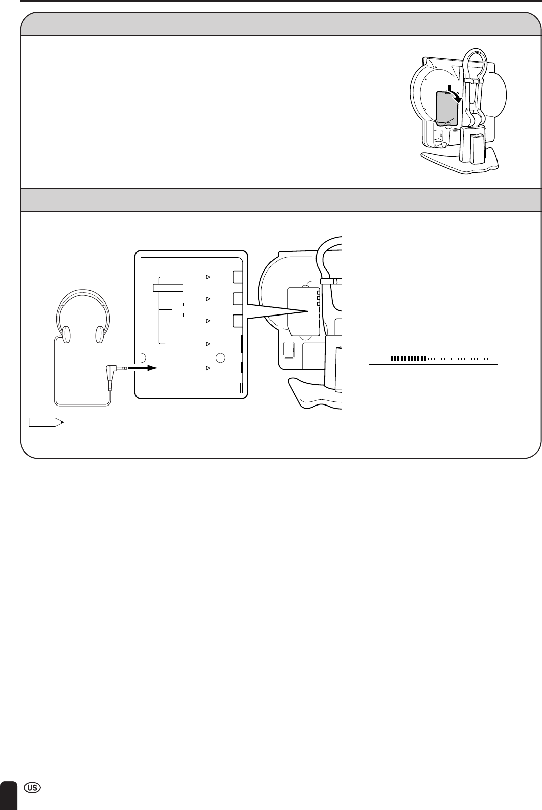
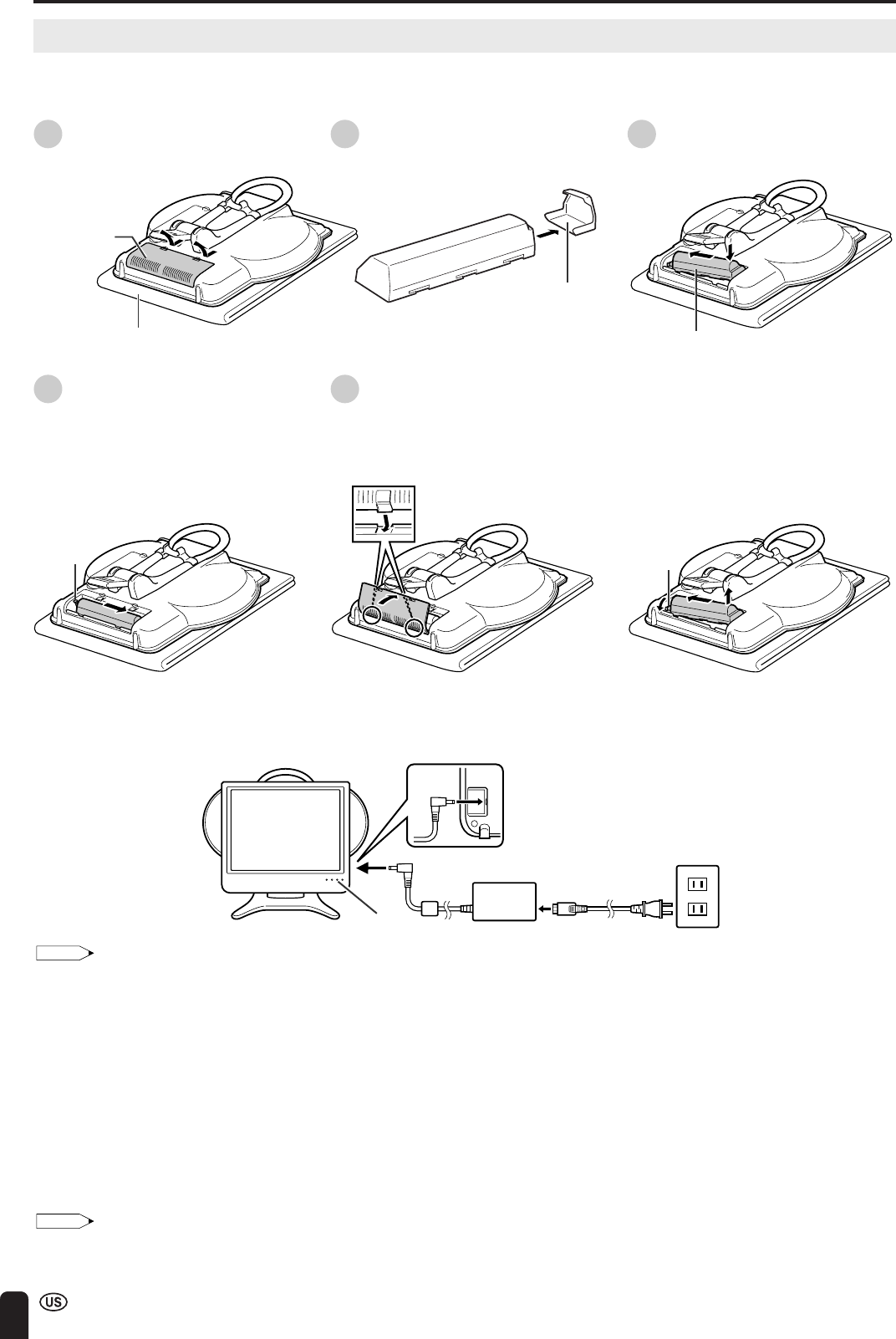
■Installing the Battery
1Open the cover of the battery
case. 2Remove the terminal cover of the
battery. 3Pack toward the left side first and
then push the battery inside the
compartment.
4Shift the battery to the right.
•The lever will return to its
original position.
•Move the battery to the right
until the lever returns
completely.
5Close the cover of the battery
case.
•Align the tabs of the cover with
the corresponding grooves in
the TV and snap into position.
■When Removing
With the lever pulled forward, lift up on
the battery while pushing to the left.
•Always make sure to attach the
terminal cover to the removed
battery.
Place on a soft cloth.
Cover of the
battery case
Terminal cover
Battery
Lever
Lever
ENGLISH
21
POWER (Continued)
Viewing Time
about 1.5 hours
about 2 hours
about 3 hours
Remaining
battery
power
indicator
The remaining battery power indicator
changes as shown below when the battery
level becomes low.
(Green) (Green) (Red)
The remaining battery power indicator is
displayed constantly regardless of whether
the on-screen display is on or off when the
battery level is low.
BRIGHTNESS Setting
BRIGHT
NORMAL
DARK
General Reference for Battery Viewing Time
The viewing time differs according to the BRIGHTNESS setting
(page 37).
Note:
•Operating time may be shorter depending on certain conditions such
as use in cold climates.
When You Want to Check the Amount of Remaining
Battery Power
Press DISPLAY on the remote control.
•Although the remaining battery power indicator will flash red
for the first 10 seconds, it will remain lit constantly after that
time.
•The amount of remaining charge is only displayed when
operating on battery power.
•The remaining battery power indicator changes according to
battery status, temperature and conditions of use. This
indicator should be used as a reference for the amount of
battery power remaining.
When Battery is not Charging Properly
•If the CHARGE indicator begins to flash extremely rapidly during charging, this means that charging is not proceeding
normally.
•When the CHARGE indicator flashes at an interval of about a second during charging, the TV main unit is not in an
appropriate temperature range for charging. The temperature range for charging should be approximately between 50°F
(10°C) and 86°F (30°C).
•If the CHARGE indicator begins to flash extremely rapidly (at about 3 flashes a second) during charging, this means that
charging is not proceeding normally because the battery may malfunction. Replace the battery with the new one.
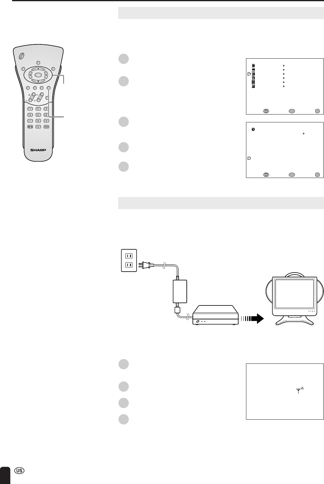
Viewing with a Home AC Wall Outlet
Plug the AC adapter of the Wireless Center and AC adapter of the TV main unit into an AC wall outlet.
•Check to make sure that the proper voltages indicated on the products are being used when plugging the AC adapters into
their respective DC terminals.
•If there is a Sharp product close to the video controller, the product may malfunction during transmission of the video
controller.
■Using the AC Adapter
•Although the AC adapters may become warm during use, this is not a malfunction.
•Do not wrap or cover the AC adapters with a blanket or similar covering. This can cause a malfunction or accident.
•Do not attempt to disassemble or modify the AC adapters. The insides of the AC adapter contain high-voltage components
that can result in the risk of electrical shock.
AC wall
outlet
AC adapter AC cord
TV main unit
AC wall
outlet
AC adapter
AC cord
IR
OUT
POWER
INPUT
DC12V
FACTORY
SETTING
Wireless
Center
22
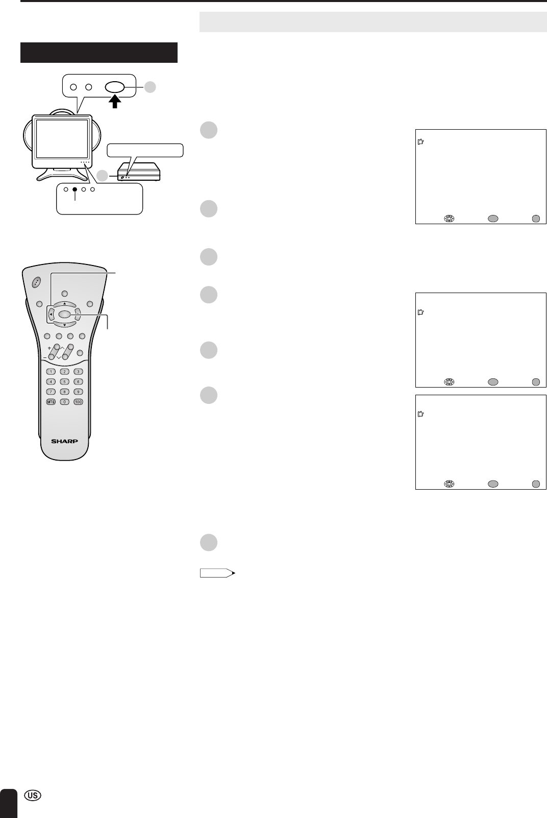
EZ SETUP (WITH AUTO CLOCK SETTING)
EZ SETUP during the First Power On
■When you turn on the TV and the Wireless Center for the first time, it will
automatically memorize the broadcasting channels and clock.
Please perform the following instructions before you press MAIN POWER.
(1) Insert the batteries into the remote control. (See page 11.)
(2) Connect the antenna cable to the Wireless Center. (See page 12.)
(3) Connect the AC adapter to the POWER INPUT terminal of the product and
plug in the AC cord to the wall outlet. (See page 13.)
1Press MAIN POWER of the TV main
unit.
•The “SELECT LANGUAGE” screen
with a list of the languages for the on-
screen display appears.
•The POWER indicator of the TV main
unit turns green.
2Press MAIN POWER of the Wireless
Center unit.
•The POWER indicator of the Wireless
Center turns green.
3Press a/b to select “ENGLISH”,
“ESPAÑOL” (SPANISH) or “FRANCAIS”
(FRENCH), and press ENTER.
4Press a/b to select “ON” or “OFF”.
When you select “ON”, the TV set will
automatically memorize the broadcasting
channels.
5Press ENTER to access AUTO CLOCK
mode.
6Press a/b to select “ON” or “OFF”.
When you select “ON”, the TV set will
automatically search the time signals
(EDS signals), provided by some TV
stations, to adjust the clock. The AUTO
CLOCK setting may take from several
minutes to an hour depending on the
number of channels to receive and
signal status. If you know the channel of
the EDS signal carrier (PBS or other) in
your area, select “OFF” and follow the
procedure in AUTO CLOCK Setting.
(See pages 24, 25.)
7Press ENTER to access EZ SETUP
mode.
Note:
•If you select “OFF” in “EZ SETUP CH-SETTING”,
EZ SETUP will be canceled.
Control section of TV main unit
CHVOL
POWER
ENTER
DISPLAY
MUTE
SLEEP PIC. FLIP
BRIGHT TV/VIDEO MENU
FLASH-
BACK
ENTER
SELECT LANGUAGE
ENGL I SH
ESPAÑOL
FRANCA I S
SELECT : ENTER: EXIT:
ENTER
MENU
EZ SETUP
ON
AUTO CLOCK
OFF
SELECT : ENTER: EXIT:
ENTER
MENU
EZ SETUP
CH-SETT ING
ON
OFF
SELECT : ENTER: EXIT:
ENTER
MENU
POWER indicator
1
2
MAIN POWER
POWER indicator
a/b
ENGLISH
23
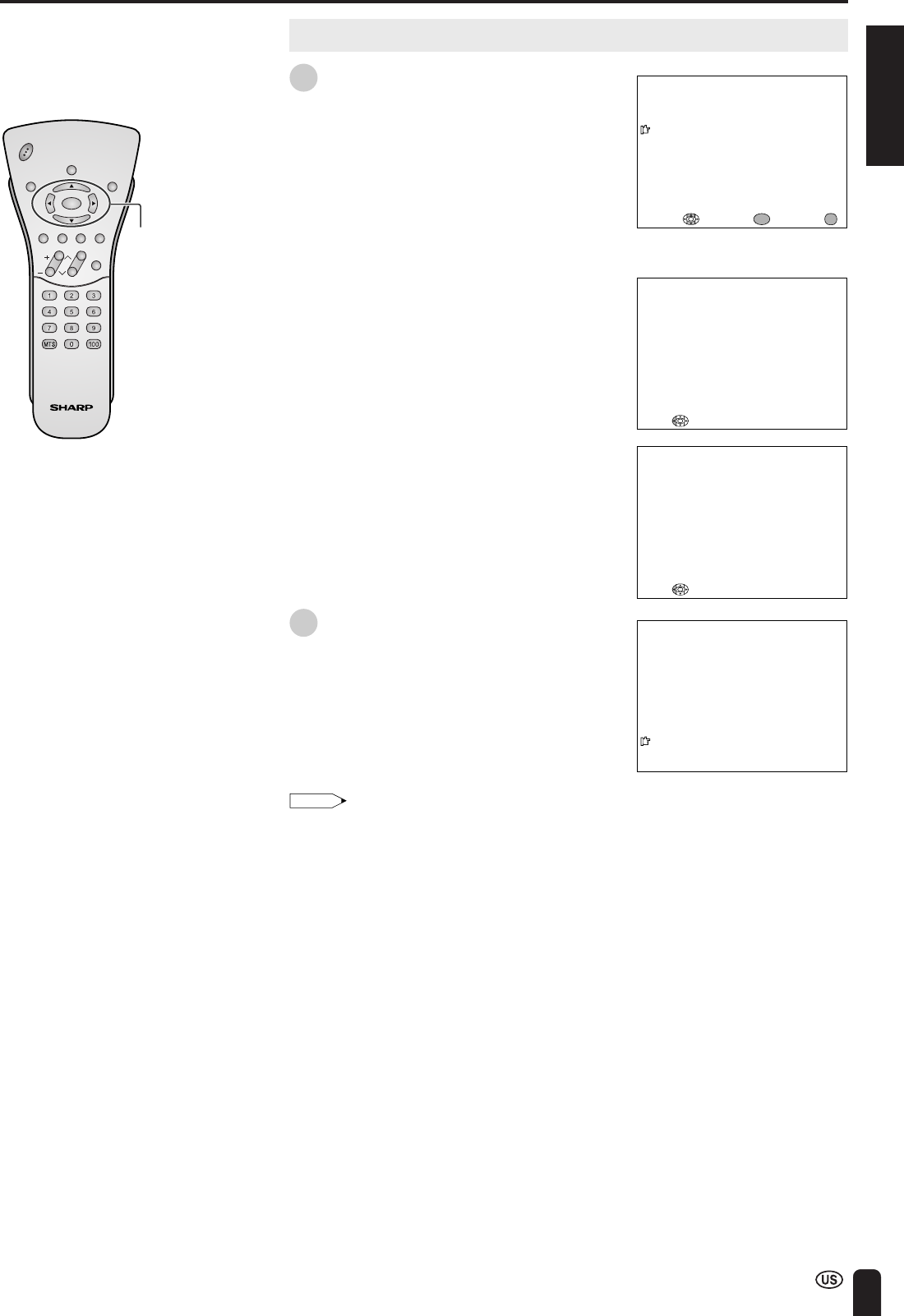
EZ SETUP (WITH AUTO CLOCK SETTING) (Continued)
START EZ SETUP?
CONNECT ANTENNA OR CABLE.
YES
NO
EXIT:
MENU
SELECT : ENTER:
ENTER
PLEASE
W
AIT
AUTO PROGRA
MM
ING
STOP:
2
STEREO
<
ON A I R
SAP
M
ONO
PLEASE
W
AIT
NO
W
SEARCH I NG T IME
STOP:
CHVOL
POWER
ENTER
DISPLAY
MUTE
SLEEP PIC. FLIP
BRIGHT TV/VIDEO MENU
FLASH-
BACK
ENTER/
a/b/c/d
EZ SETUP during the First Power On (Continued)
8Press a/b to select “YES”, and press
ENTER.
If you want to stop the EZ SETUP
process once it has started, press c
and it will be canceled. If you want to
SET UP again, please refer to pages 43
and 44 on “SET UP”.
To cancel EZ SETUP
Press c.
The tuner will automatically search for
the broadcasting and cable TV channels.
(The CH No. will automatically increase
when it appears.)
The TV set will automatically search for
EDS signals.
If EDS signals are received, the channel
number and time will be displayed, and
then the screen shown in step 8
appears.
9Once EZ SETUP is completed, the
lowest channel number memorized will
be displayed.
Note:
•Do not let the EZ SETUP screen remain unat-
tended for a long time.
•If EZ SETUP does not memorize all the channels
in your region, please refer to pages 43 and 44
for more information on manually memorizing the
channels using CH-SETTING.
•It may be difficult to preset when the broadcasting
signals are weak, the channel cycle frequency is
incorrect or the frequency jamming is occurring
around the area. Please refer to pages 43 and 44
for more information on manually memorizing
channels using CH-SETTING.
•If there are no channels with EDS signals or the
antenna signal is weak, the AUTO CLOCK setting
may not operate. In this case, a “EDS CH IS NOT
AVAILABLE” message will display and the mode
will change to MANUAL CLOCK setting. Refer to
page 26 to set the clock manually.
24
AUTO CLOCK Setting
There are two methods of setting the clock: AUTO CLOCK and MANUAL CLOCK.
AUTO CLOCK uses EDS signals, which are provided by some TV stations, to
automatically adjust the clock. MANUAL CLOCK set the clock manually in areas
where no channel carries EDS signals.
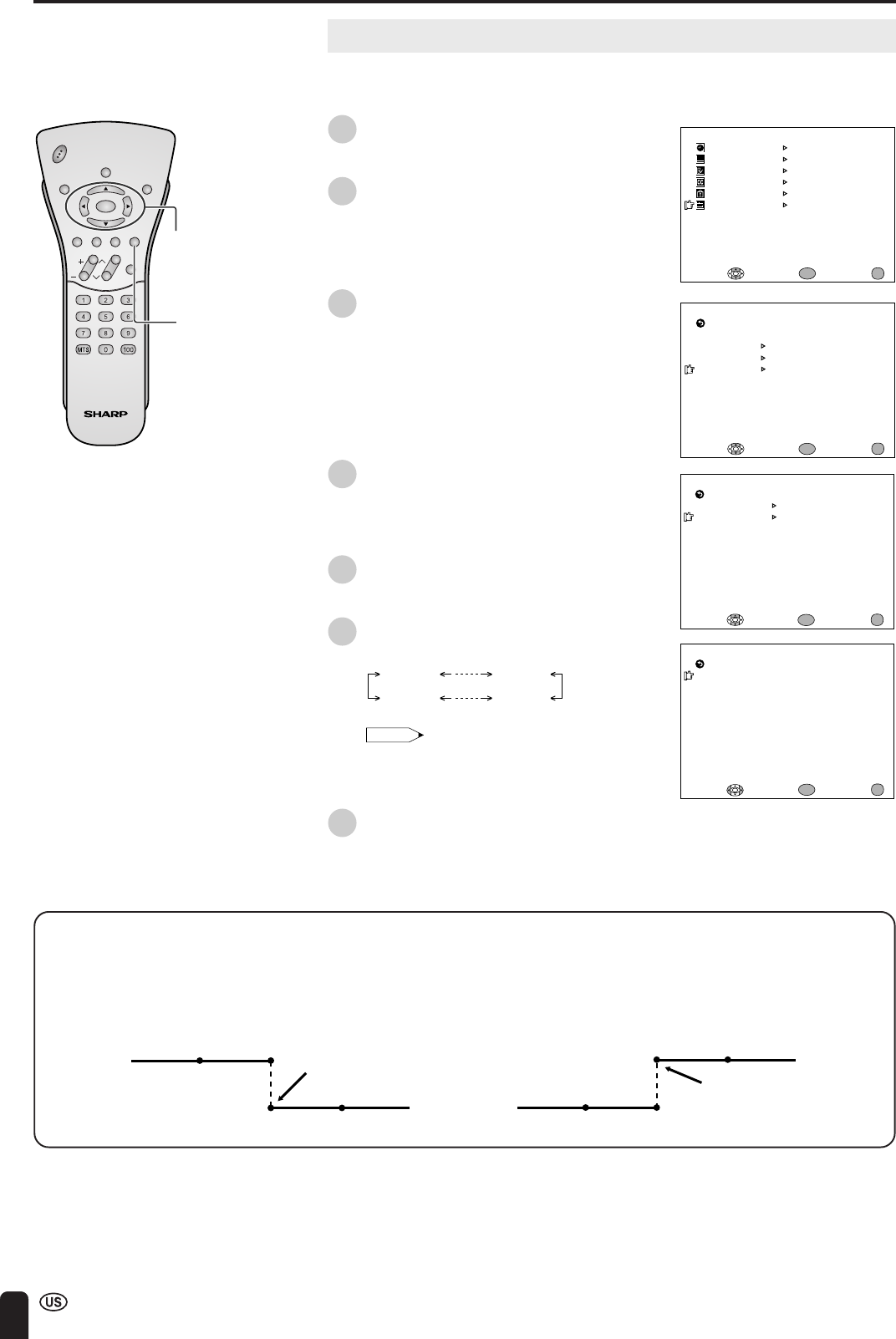
1Press MENU to display the MENU
screen.
2Press a/b to move the cursor to
“SET UP”, and press ENTER.
3Press a/b to move the cursor to
“CLOCK”, and press ENTER.
4Press a/b to move the cursor to
“AUTO CLOCK”, and press ENTER.
Note:
•The CLOCK can be stopped completely by
setting “CLOCK” to “OFF”.
SETTING THE CLOCK
CLOCK
AUTO CLOCK
M
ANUAL CLOCK
OFF
SELECT : ENTER: EXIT:
RETURN
ENTER
MENU
M
ENU
SLEEP T I
M
ER
V IDEO ADJUST
PRESET
CLOSED CAPT ION
V–CHIP BLOCK
SET UP
SELECT : ENTER: EXIT:
ENTER
MENU
BLUE SCREEN [OFF]
LANGUAGE
SELECT : EXIT:
ENTER
RETURN SET UP
CH–SETT I NG
ENTER:
MENU
CLOCK
CHVOL
POWER
ENTER
DISPLAY
MUTE
SLEEP PIC. FLIP
BRIGHT TV/VIDEO MENU
FLASH-
BACK
ENTER
MENU
Time reset for power outage or AC adapter disconnected
If the TV has a power outage or the AC adapter cord is disconnected, the time display will have to be reset. In that
case, refer to “AUTO CLOCK Setting” and “MANUAL CLOCK Setting” on pages 24 to 26.
a/b
ENGLISH
25
SETTING THE CLOCK (Continued)
ENTER/
a/b/c/d
MENU
AUTO CLOCK
EDS CH SET [AUTO ]
EXIT:
RETURN
EDS CH [ –––]
START
ENTER:
ENTER
ADJUST :
MENU
PLEASE
W
AIT
NO
W
SEARCH I NG T IME
STOP:
2
STEREO
<
ON A I R
SAP
M
ONO
CHVOL
POWER
ENTER
DISPLAY
MUTE
SLEEP PIC. FLIP
BRIGHT TV/VIDEO MENU
FLASH-
BACK
AUTO CLOCK Setting (Continued)
5Press a/b to move the cursor to “EDS
CH SET”, and press ENTER.
6Press c/d to select “AUTO” or
“MANUAL”.
7Press a/b to move the cursor to
“START”, and press ENTER.
To cancel AUTO CLOCK
Press c.
|If you do not know the channel that carries
EDS signals in your area, select “EDS CH
SET” to “AUTO” and select “START”. If
you know the channel of the EDS signal
carrier in your area, select “EDS CH SET”
to “MANUAL”. Set the EDS CH and select
“START”.
|When set to “AUTO CLOCK”, the time is
acquired automatically when MAIN
POWER is turned OFF. (This function will
not work when EDS CH is not set.)
Note:
•CLOCK: The AUTO CLOCK setting may take
from several minutes to an hour depending on the
number of channels to receive and signal status.
•If there are no channels with EDS signals or the
antenna signal is weak, the AUTO CLOCK setting
may not operate. In this case, an “EDS CH IS
NOT AVAILABLE” message will display, and the
MANUAL CLOCK Setting screen appears. Refer
to “MANUAL CLOCK Setting” on page 26 to set
the clock manually.
•If you know the Channel of the EDS signal carrier
in your area, set “EDS CH SET” to “MANUAL”
and select “START”. In case, the message “EDS
CH (XXX) EDS DATA IS NOT AVAILABLE”
displays, set “EDS CH SET” to “AUTO” when the
AUTO CLOCK setting screen appears.
•If broadcasting channels are not memorized, EDS
signals cannot be received even when the “EDS
CH SET” is set to “AUTO”. In this case, try EZ
SETUP again. (See page 43.)
26
MANUAL CLOCK Setting
If there are no channels with EDS signals, set the clock manually using MANUAL
CLOCK.
1Press MENU to display the MENU
screen.
2Press a/b to move the cursor to
“SET UP”, and press ENTER.
3Press a/b to move the cursor to
“CLOCK”, and press ENTER.
4Press a/b to move the cursor to
“MANUAL CLOCK”, and press ENTER.
5Press a/b to move the cursor to
“TIME”, and press ENTER.
6Press c/d to set the time, and press
ENTER.
12:00AM 11:59AM
11:59PM 12:00PM
Note:
•Make sure to press ENTER after adjusting
the time. Otherwise, the time will not be
set.
7Press MENU to return to the main
screen.
SETTING THE CLOCK (Continued)
ENTER/
a/b/c/d
MENU
Daylight Saving-Time (DST) Adjustment
The Daylight Saving-Time changes as shown below. Set the “DST” to “ON” to forward the clock by 1 hour. To rewind
the clock by 1 hour, set the “DST” to “OFF”.
(Spring)
On the first Sunday in April D.S.T. starts.
(Autumn)
On the last Sunday in October D.S.T. finishes.
Advances 1 hour.
Rewinds 1 hour.
CHVOL
POWER
ENTER
DISPLAY
MUTE
SLEEP PIC. FLIP
BRIGHT TV/VIDEO MENU
FLASH-
BACK
M
ENU
SLEEP T I
M
ER
PRESET
CLOSED CAPT ION
V–CHIP BLOCK
SET UP
SELECT : EXIT:
V IDEO ADJUST
ENTER:
ENTER
MENU
CLOCK
AUTO CLOCK
M
ANUAL CLOCK
OFF
SELECT : ENTER: EXIT:
RETURN
ENTER
MENU
M
ANUAL CLOCK
T IME [ 12: 00AM]
EXIT:
RETURN
DST [OFF ]
ENTER:
ENTER
ADJUST :
MENU
BLUE SCREEN [OFF]
LANGUAGE
SELECT : EXIT:
ENTER
RETURN SET UP
CH–SETT I NG
ENTER:
MENU
CLOCK
1:00AM 2:00AM
3:00AM 4:00AM
1:00AM 2:00AM
1:00AM 2:00AM

ENGLISH
27
TV SIGNALS IN YOUR REGION
This product is factory set to comply with the TV broadcasting system in the United States.
Country TV broadcasting Factory setting of color system User setting
system TV Video TV
U.S.A. Color: NTSC NTSC (N358) N358
TV ch: US ch US ch Not required or N/A
Canada Color: NTSC NTSC (N358) N358
TV ch: US ch US ch Not required or N/A
28
BATTERY CHARGE AND TRANSMISSION SETTING
Battery Charge
The “BATTERY CHARGE” is set to “ON” when shipped from the factory. The
battery will deteriorate if it continues to be charged after having been fully charged.
It is recommended to set the “BATTERY CHARGE” to “OFF” when the battery
is not used frequently.
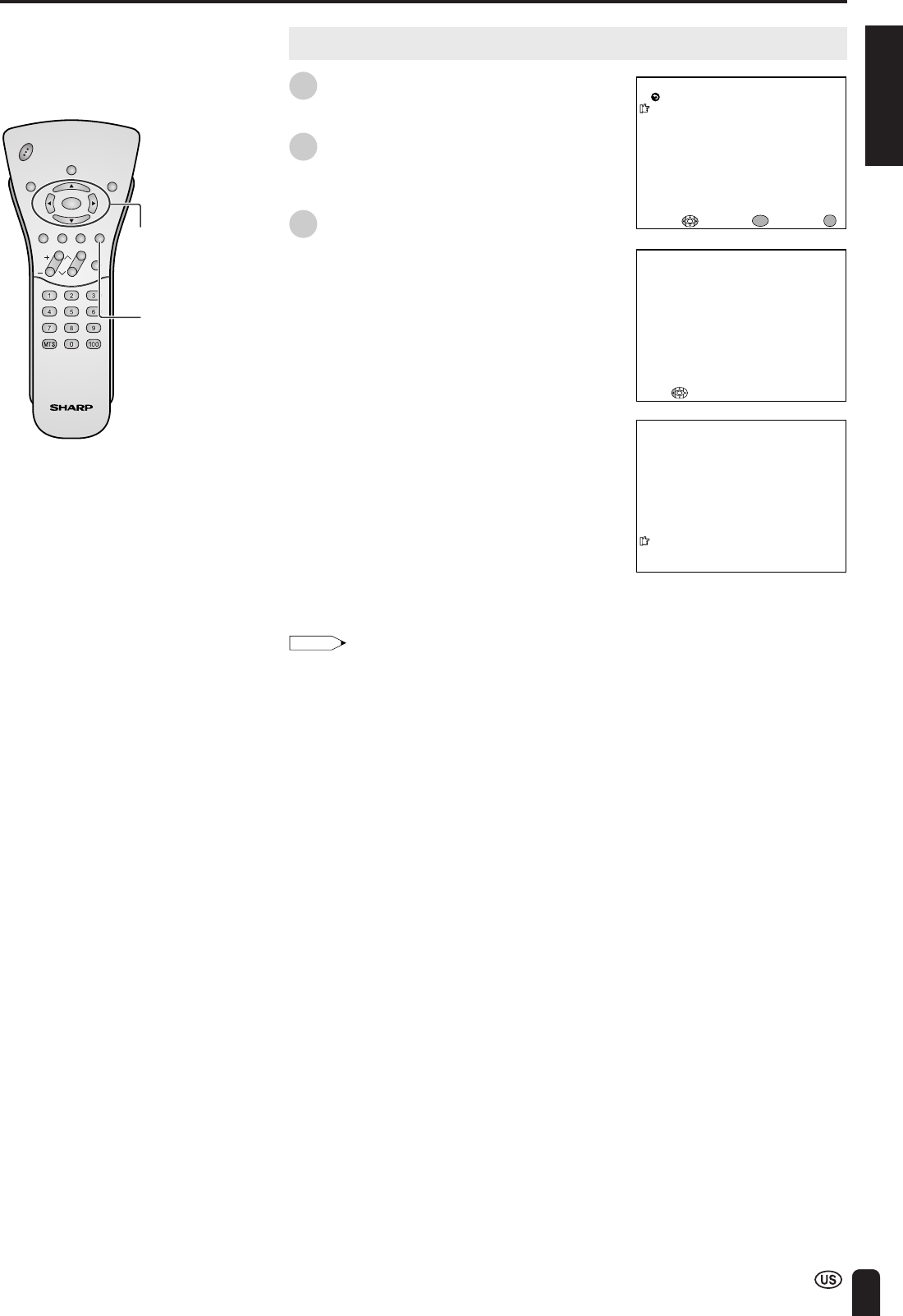
1Press MENU to display the MENU
screen.
2Press a/b to move the cursor to
“PRESET”, and press ENTER.
3Press a/b to move the cursor to
“BATTERY CHARGE”, and press
ENTER.
4Press c/d to change the setting, and
press ENTER.
5Press MENU to return to the main
screen.
Transmission Setting
When shipped from the factory, the “CHANNEL” of the “TRANSMISSION
SETTING” is set to “AUTO”, and the “DISTANCE” is set to “NEAR”. However,
when reception is poor due to the presence of an interference source in close
proximity, change the settings for “CHANNEL” or “DISTANCE” to ensure normal
reception.
ENTER/
a/b/c/d
MENU
[1] Preparing for “TRANSMISSION SETTING”
1Connect the antenna to the Wireless
Center.
2Install the Wireless Center and TV
receiver next to each other.
3Turn on the power for both the Wireless
Center and TV receiver.
4Press MENU to display the MENU
screen.
CHVOL
POWER
ENTER
DISPLAY
MUTE
SLEEP PIC. FLIP
BRIGHT TV/VIDEO MENU
FLASH-
BACK
M
ENU
SLEEP T I
M
ER
V IDEO ADJUST
PRESET
CLOSED CAPT ION
V–CHIP BLOCK
SET UP
SELECT : ENTER: EXIT:
ENTER
MENU
AC cord
AC wall
outlet
AC adapter
Wireless
Center
Transmission
TV main unit
NOW ACCESSING.
BR I GHTNESS [ BR I GHT ]
M
TS
AUTO PO
W
ER OFF
RETURN
[STEREO]
[OFF ]
PICTURE FLIP
AV2 IN/OUT
BATTERY
CHARGE
[NOR
M
AL ]
[IN ]
[ON ]
PRESET
TRANSMISSION SETTING
SELECT : ENTER: EXIT:
ENTER
MENU
ENGLISH
29
Transmission Setting (Continued)
5Press a/b to move the cursor to
“PRESET”, and press ENTER.
6Press a/b to move the cursor to
“TRANSMISSION SETTING”, and press
ENTER.
[2] Setting Channel
Four settings can be selected for the communication channel consisting of
Auto, A, B and C. When set to “AUTO”, available channels that can be
transmitted are set automatically. It is recommended to normally set the
communication channel to “AUTO”.
AUTO A B C
1Press a/b to select “CHANNEL”, and
then press ENTER.
2Press c/d to select “AUTO”, and then
press ENTER.
•The available settings change in the
order shown below each time c/d is
pressed.
AUTO A B C
•“ADJUSTING CHANNEL SETTING.” is
displayed on the screen and the
communication channel is set
automatically.
M
ENU
SLEEP T I
M
ER
V IDEO ADJUST
PRESET
CLOSED CAPT ION
V–CHIP BLOCK
SET UP
SELECT : ENTER: EXIT:
ENTER
MENU
BR I GHTNESS [ BR I GHT ]
M
TS
AUTO PO
W
ER OFF
RETURN
[STEREO]
[OFF ]
PICTURE FLIP
AV2 IN/OUT
BATTERY
CHARGE
[NOR
M
AL ]
[IN ]
PRESET
TRANSMISSION SETTING
SELECT : ENTER: EXIT:
ENTER
MENU
[ON ]
STATUS: A
[ A]
DISTANCE
RETURN
[ FAR] STATUS: NEAR
TRANSMISSION SETTING
CHANNEL
SELECT : ENTER: EXIT:
ENTER
MENU
Displayed in yellow
BATTERY CHARGE AND TRANSMISSION SETTING (Continued)
ADJUSTING CHANNEL SETTING.
CHVOL
POWER
ENTER
DISPLAY
MUTE
SLEEP PIC. FLIP
BRIGHT TV/VIDEO MENU
FLASH-
BACK
ENTER/
a/b/c/d
MENU
[ AUTO ]
DISTANCE
RETURN
[ FAR] STATUS: NEAR
TRANSMISSION SETTING
CHANNEL
SELECT : ENTER: EXIT:
ENTER
MENU
Note:
•If “CHANNEL” is set to “AUTO”, when switching on the power or when setting the
communication channel, a connection is automatically made to an empty channel A,
B, or C.
∗As this is not the function to automatically switch channels to an empty channel
when the reception conditions deteriorate, try to switch manually to another
channel with better reception conditions in such a case.
•This unit uses the three communication channels A, B, and C for wireless
transmission of video and audio signals.
When microwave ovens, wireless LANs, or devices using Bluetooth transmission
technology that use the same 2.4GHz frequency band are operating in the vicinity,
they may cause interference possibly making reception impossible.
In this case, changing to another transmission channel may avoid this type of
interference.
30
■Errors on the communication conditions
1Press a/b to select “DISTANCE”, and
then press ENTER.
2Press c/d to select the desired
distance, and then press ENTER.
•“ADJUSTING DISTANCE SETTING.” is
displayed on the screen and the
communication distance is set
automatically.
3Press MENU to return to the main
screen.
Note:
•Automatic channel selection is only made
when the TV main unit is first switched on
or when the function is selected from the
menu.
•If reception has become poor after
changing the locations of the Wireless
Center and TV receiver, the problem may
be corrected by resetting the
communication channel and
communication distance.
Transmission Setting (Continued)
[3] Setting Distance
Select the DISTANCE mode that gives the best reception and picture quality.
FAR
MID
NEAR
Setting
Picture
Quality
Data Error
Correction
NEAR
Best
Weak
Worst
Strong
MID FAR
BATTERY CHARGE AND TRANSMISSION SETTING (Continued)
STATUS: A
DISTANCE
RETURN
[ FAR] STATUS: NEAR
TRANSMISSION SETTING
CHANNEL [ AUTO]
Displayed in yellow
ADJUST ING D I STANCE SETT I NG.
CHVOL
POWER
ENTER
DISPLAY
MUTE
SLEEP PIC. FLIP
BRIGHT TV/VIDEO MENU
FLASH-
BACK
STATUS: A
DISTANCE
RETURN
[NEAR]
TRANSMISSION SETTING
CHANNEL [ AUTO]
ENTER/
a/b/c/d
MENU
NEAR: Enables finer picture quality.
MID: Enables normal picture
quality and middle distance
transmission.
FAR: Enables longer distance
transmission. (Picture quality
becomes relatively poor.)
Error message
SIGNAL COULD NOT
BE RECEIVED
SIGNAL COULD NOT
BE RECEIVED
WEAK SIGNAL
Color
Red
Yellow
Yellow
Description
Continues to be indicated as long as no signal is
received.
Indicates no connection can be made to the
Wireless Center due to interference of radio
waves. The indication is red initially, and
changes to yellow after approximately 10
seconds. When using a fixed channel (A, B,
or C), set to “AUTO” or try switching to another
channel to connect to the Wireless Center.
Is indicated for 10 seconds, then goes out
temporarily. This operation is repeated every 10
minutes.
* Interference of radio waves denotes radio waves in the 2.4GHz frequency wave
band complying with the IEEE802.11b specifications. Since this function cannot
detect radio waves in the 2.4GHz frequency wave band other than those that
comply with the IEEE802.11b specifications, no yellow indication will appear should
such radio waves be the cause of interference.
ENGLISH
31
POWER indicator
1
2
MAIN POWER
POWER indicator
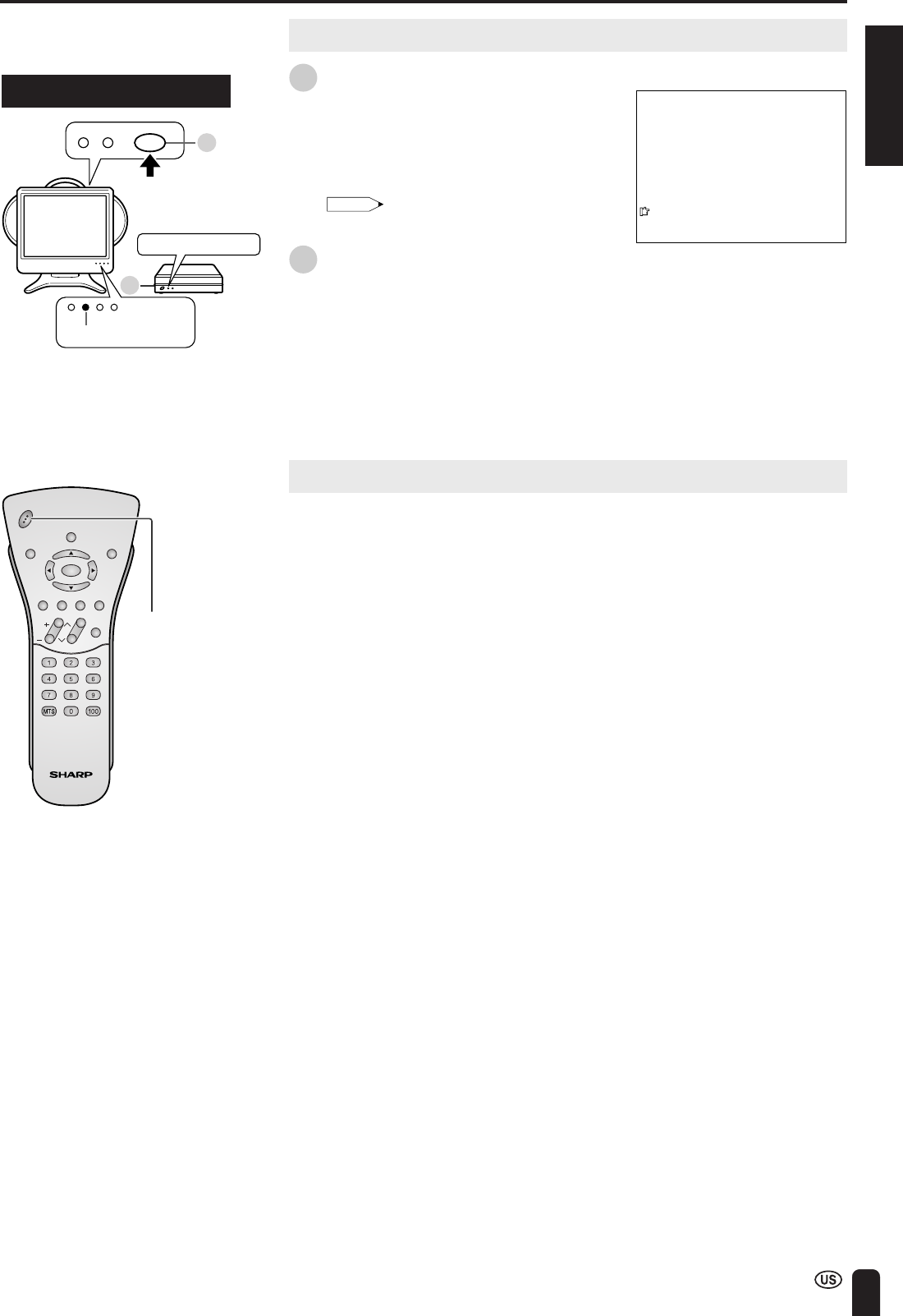
BASIC OPERATION
Turning on POWER
1Press MAIN POWER of the TV main
unit.
•“NOW ACCESSING.” is displayed on
the screen.
•The POWER indicator of the TV main
unit turns green.
Note:
•The On-screen indicator disappears after a
few seconds.
2Press MAIN POWER of the Wireless
Center.
•The POWER indicator of the Wireless
Center turns green.
Standby
To turn off the LCD TV
Press POWER on the remote control.
•The POWER indicator turns red.
To turn the LCD TV back on
Press POWER again.
•The POWER indicator turns green.
Control section of TV main unit
CHVOL
POWER
ENTER
DISPLAY
MUTE
SLEEP PIC. FLIP
BRIGHT TV/VIDEO MENU
FLASH-
BACK
POWER
▼ On-screen display
2
STEREO
SAP
M
ONO
32
BASIC OPERATION (Continued)
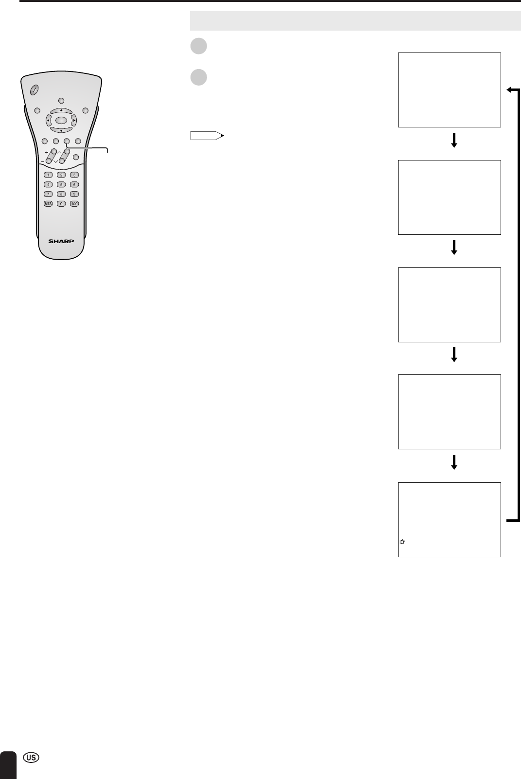
Switching TV/VIDEO [AV1/AV2/AV3/AV4] Modes
1Turn on the power of the connected
video equipment.
2Press TV/VIDEO and select the
applicable input source. The screen
displays AV1, AV2, AV3, AV4 or TV
mode each time TV/VIDEO is pressed.
Note:
•The AV input mode indication remains for
3 seconds.
•AV1: Video equipment connected to the AV-IN1
input terminals.
The S-video input terminal is additionally
provided for the AV-IN1 input.
If both the S-video terminal and normal
video terminals are connected with cables,
the S-video input terminal takes priority.
•AV2: AV2 mode is used to adjust the preset
settings and “IN” or “OUT” can be selected.
AV2 indication is not displayed when “OUT”
is selected. (For details on setting AV2 IN/
OUT, see page 39.)
•AV3: Video equipment connected to the AV-IN3
input terminals.
•AV4: The AV4 input terminal is in the TV main
unit. This terminal is for directly connecting
to an external device such as a game
device.
If both the S-video terminal and normal
video terminals are connected with cables,
the S-video input terminal takes priority.
CHVOL
POWER
ENTER
DISPLAY
MUTE
SLEEP PIC. FLIP
BRIGHT TV/VIDEO MENU
FLASH-
BACK
TV/VIDEO
AV2
AV3
12
AV1
AV4
STEREO
<
ON A I R
SAP
M
ONO
AV1 mode
AV2 mode
TV mode
AV3 mode
AV4 mode
ENGLISH
33
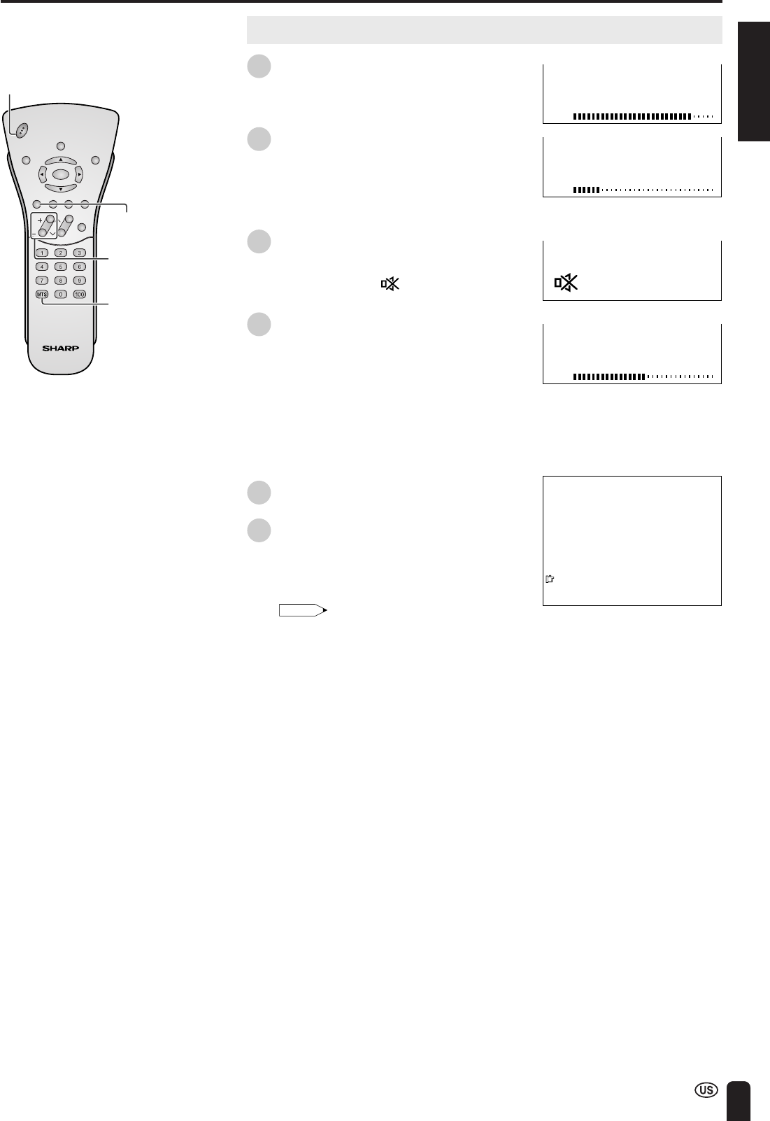
Sound Volume
1Press VOL (+) to increase the sound
volume. The bar indicator shifts right.
2Press VOL (–) to decrease the sound
volume. The bar indicator shifts left.
To mute the sound
1Press MUTE to temporarily turn off the
sound.
The MUTE mark “” is displayed for 4
seconds.
2Press MUTE or VOL (+)/(–) to turn the
sound back to the previous level.
The mute function is automatically
turned off when any of the following
buttons are pressed: POWER, VOL (+)/
(–) or MTS.
To select MTS (Multichannel TV Sound)
1Press MTS to display the MTS screen.
2Press MTS to select the MTS settings.
STEREO: stereo audio
SAP: secondary audio program
MONO: monophonic audio
Note:
•“<ON AIR” appears when a STEREO or
SAP broadcast is being aired.
BASIC OPERATION (Continued)
CHVOL
POWER
ENTER
DISPLAY
MUTE
SLEEP PIC. FLIP
BRIGHT TV/VIDEO MENU
FLASH-
BACK
MUTE
VOL
(+)/(–)
MTS
POWER
50
VOLUME
10
VOLUME
30
VOLUME
2
STEREO
<
ON A I R
SAP
M
ONO
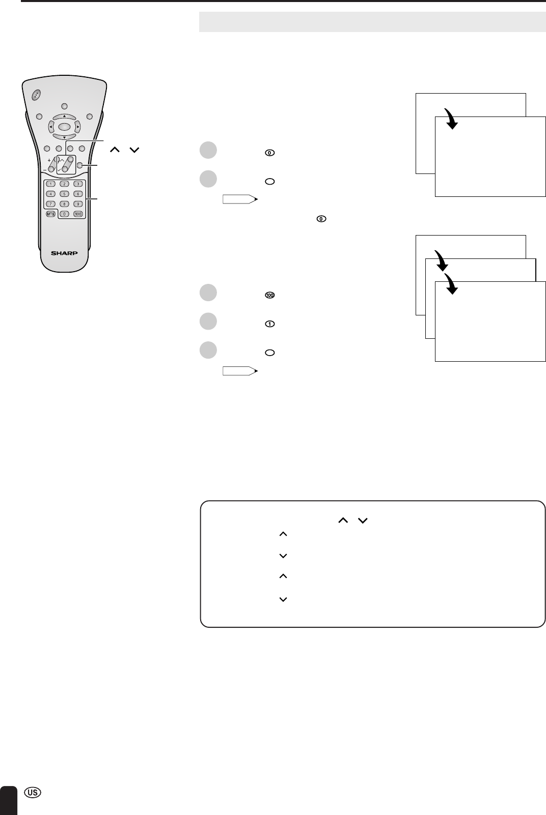
34
Changing Channels
Changing channels by using Channel Select on the remote control
•This LCD TV set allows you to select up to 125 channels (1 to 125). To
select a channel, enter a 2- or 3-digit number.
To select a 1- or 2-digit channel
number (e.g., Channel 5):
Complete the following procedure within 4
seconds.
1Press the button.
2Press the
5
button.
Note:
•When selecting a 1-digit channel number,
do not fail to press the button first.
To select a 3-digit channel number
(e.g., Channel 115):
Complete the following procedure within 4
seconds.
1Press the button.
2Press the button.
3Press the
5
button.
Note:
•The 3-digit channel number can be
selected only when the receiving mode is
set to “CABLE” in “CH-SETTING”. (For
details on setting the receiving mode, see
page 43.)
•Press FLASHBACK to show the previous
channel.
•Tuning operation may take a few seconds to
complete when using the remote control,
because of the wireless transmission speed.
This does not indicate a malfunction.
BASIC OPERATION (Continued)
Channel
Select
CH
()/( )
FLASH-
BACK
Changing channels with CH ( )/( ) on the remote control
Air Press CH ( ) and the channels change in the order shown below:
2 → 3 → . . . → 68 → 69 → 2 → 3 → . . .
Press CH ( ) and the channels change in the order shown below:
3 → 2 → 69 → 68 → . . . → 3 → 2 → . . .
Cable Press CH ( ) and the channels change in the order shown below:
1 → 2 → 3 → . . . → 125 →1 → 2 → 3 → . . .
Press CH
( ) and the channels change in the order shown below:
3 → 2 → 1 → 125 → . . . → 3 → 2 → 1 → . . .
CHVOL
POWER
ENTER
DISPLAY
MUTE
SLEEP PIC. FLIP
BRIGHT TV/VIDEO MENU
FLASH-
BACK
0–
5
1––
11–
115
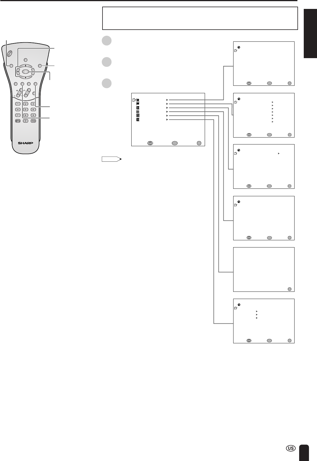
ENGLISH
35
•This LCD TV set allows you to adjust the various settings using the MENU
screen. Select the desired menu item by following the steps below and then
refer to the indicated page for details.
1Press MENU to display the MENU
screen.
2Press a/b to select the desired menu
item, and press ENTER.
3Press MENU to exit.
SELECTING MENU ITEMS
Note:
•The displayed items differ depending on the
setting conditions.
•The selected item changes to yellow.
•Items in magenta cannot be selected.
•To return to the previous screen, select
“RETURN”.
•You can adjust some settings with the special
buttons: SLEEP, BRIGHT and PIC. FLIP (see
pages 36 to 38).
* The illustrations and on-screen displays in this
operation manual are for explanation purposes
and may vary slightly from the actual opera-
tions.
ENTER
BRIGHT
M
ENU
SLEEP T I
M
ER
V IDEO ADJUST
PRESET
CLOSED CAPT ION
V–CHIP BLOCK
SET UP
SELECT : ENTER: EXIT:
ENTER
MENU
BRIGHTNESS [ BR IGHT ]
M
TS
AUTO PO
W
ER OFF
RETURN
[STEREO]
[OFF ]
PICTURE FLIP
AV2 IN/OUT [NOR
M
AL ]
[IN ]
[ ON ]
PRESET
TRANSMISSION SETTING
PICTURE [ 50]
TINT
COLOR
BLACK LEVEL
SHARPNESS
SELECT : ENTER: EXIT:
V I DEO ADJUST ( TV )
RETURN
[ 0]
[ 0]
[ 0]
[ 0]
RED-BLUE [ 0]
GREEN [ 0]
RESET
ENTER
MENU
SLEEP T I
M
ER
SELECT : ENTER: EX I T :
ENTER
RETURN
SLEEP T I
M
ER [––– RE
M
AIN]
ENTER
ENTER:
CC/ TEXT [OFF]
SELECT : EXIT:
RETURN CLOSED CAPT ION
INPUT SECRET NO.
– – – –
EXIT:
MENU
MENU
MENU
SELECT : ENTER: EXIT:
ENTER
MENU
BLUE SCREEN [OFF]
LANGUAGE
SELECT : EX I T :
ENTER
RETURN SET UP
CH–SETT ING
ENTER:
MENU
CLOCK
BATTERY CHARGE
CHVOL
POWER
ENTER
DISPLAY
MUTE
SLEEP PIC. FLIP
BRIGHT TV/VIDEO MENU
FLASH-
BACK
MENU
PIC. FLIP
SLEEP
a/b
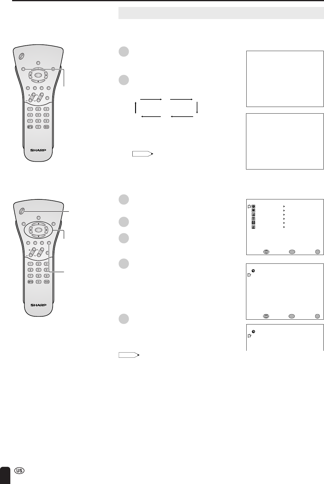
36
ADJUSTMENTS
Adjusting SLEEP TIMER Settings
You can set the SLEEP TIMER to automatically turn off the TV.
Directly setting the SLEEP TIMER
1Press SLEEP to display the SLEEP
TIMER screen.
2Press SLEEP to set the sleep timer (in
minutes).
---
120
30 60
90
(minutes)
150
•The SLEEP TIMER is turned off when
“---” is displayed.
Note:
•The SLEEP TIMER screen automatically
disappears in 3 seconds.
Setting the SLEEP TIMER on the
MENU screen
1Press MENU to display the MENU
screen.
2Press a/b to move the cursor to
“SLEEP TIMER”.
3Press ENTER to display the SLEEP
TIMER screen, and press ENTER.
4Press c/d to set the sleep timer (in
minutes), and press ENTER.
•The time can be set in increments of
30 minutes and in the range between
30 and 150 minutes.
•The SLEEP TIMER is turned off when
“---” is displayed.
5Press MENU to return to the main
screen.
Note:
•When you set the SLEEP TIMER, the SLEEP
indicator lights up red.
•After you set the SLEEP TIMER, pressing MAIN
POWER on the TV set or POWER on the remote
control will cancel the SLEEP TIMER setting and
the SLEEP indicator goes out.
•5 minutes before the SLEEP TIMER turns off the
TV, “5 REMAIN” is displayed on the screen for 4
seconds. The SLEEP TIMER counts down and
shows a similar 4-second display for each
remaining minute until the timer turns off the TV.
––– REMA I N
60 REMAIN
SLEEP T I
M
ER
SELECT : EXIT:
RETURN
SLEEP T I
M
ER [––– RE
M
AIN]
ENTER:
ENTER
MENU
SLEEP T I
M
ER
RETURN
SLEEP T I
M
ER [–60 RE
M
AIN]
M
ENU
SLEEP T I
M
ER
V IDEO ADJUST
PRESET
CLOSED CAPT ION
V–CHIP BLOCK
SET UP
SELECT : ENTER: EXIT:
ENTER
MENU
CHVOL
POWER
ENTER
DISPLAY
MUTE
SLEEP PIC. FLIP
BRIGHT TV/VIDEO MENU
FLASH-
BACK
SLEEP
CHVOL
POWER
ENTER
DISPLAY
MUTE
SLEEP PIC. FLIP
BRIGHT TV/VIDEO MENU
FLASH-
BACK
ENTER/
a/b/c/d
MENU
POWER
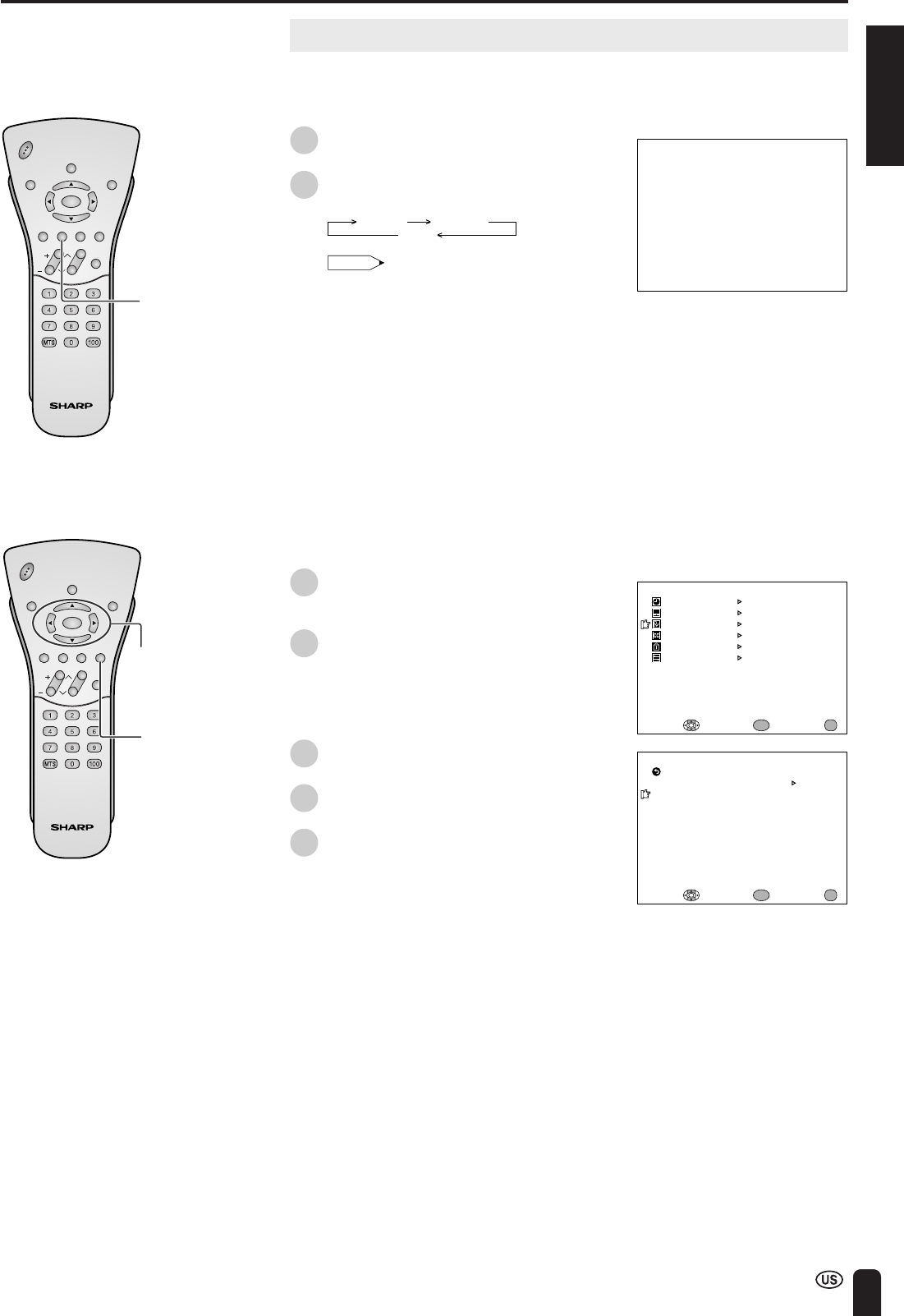
ENGLISH
37
ADJUSTMENTS (Continued)
BR IGHTNESS[BR IGHT ]
M
ENU
SLEEP T I
M
ER
V IDEO ADJUST
PRESET
CLOSED CAPT ION
V–CHIP BLOCK
SET UP
SELECT : ENTER: EXIT:
ENTER
MENU
BRIGHTNESS [BRI GHT ]
M
TS
AUTO PO
W
ER OFF
RETURN
[STEREO]
[OFF ]
PICTURE FLIP
BATTERY CHARGE
AV2 IN/OUT [NOR
M
AL ]
[IN ]
[ON ]
PRESET
TRANSMISSION SETTING
SELECT : ENTER: EXIT:
ENTER
MENU
CHVOL
POWER
ENTER
DISPLAY
MUTE
SLEEP PIC. FLIP
BRIGHT TV/VIDEO MENU
FLASH-
BACK
ENTER/
a/b/c/d
CHVOL
POWER
ENTER
DISPLAY
MUTE
SLEEP PIC. FLIP
BRIGHT TV/VIDEO MENU
FLASH-
BACK
BRIGHT
MENU
Adjusting BRIGHTNESS Settings
You can adjust the brightness of the screen.
Directly setting the BRIGHTNESS
1Press BRIGHT to display the
BRIGHTNESS screen.
2Press BRIGHT to change the setting.
BRIGHT
DARK
NORMAL
Note:
•The BRIGHTNESS screen automatically
disappears in 3 seconds.
•[BRIGHT]: maximum brightness
[NORMAL]:60% brightness (Suitable for
viewing in a well-lit area. Saves
energy.)
[DARK]: 10% brightness (Sufficiently
bright when viewing in dim
areas.)
Setting the BRIGHTNESS on the MENU
screen
1Press MENU to display the MENU
screen.
2Press a/b to move the cursor to
“PRESET”, and press ENTER.
3Press a/b to move the cursor to
“BRIGHTNESS”, and press ENTER.
4Press c/d to change the setting, and
press ENTER.
5Press MENU to return to the main
screen.
38
ADJUSTMENTS (Continued)
P I CTURE FL I P [ NOR
M
AL]
PICTURE FLIP [MIRROR]
PI CTURE FL I P [ROTATE ]
P I CTURE FL I P [UPS I DE DO
W
N]
ABC
ABC
ABC
ABC
M
ENU
SLEEP T I
M
ER
V IDEO ADJUST
PRESET
CLOSED CAPT ION
V–CHIP BLOCK
SET UP
SELECT : ENTER: EXIT:
ENTER
MENU
CHVOL
POWER
ENTER
DISPLAY
MUTE
SLEEP PIC. FLIP
BRIGHT TV/VIDEO MENU
FLASH-
BACK
ENTER/
a/b/c/d
CHVOL
POWER
ENTER
DISPLAY
MUTE
SLEEP PIC. FLIP
BRIGHT TV/VIDEO MENU
FLASH-
BACK
PIC. FLIP
MENU
Adjusting PICTURE FLIP Settings
You can set the orientation of the picture.
Directly setting the PICTURE FLIP
1Press PIC. FLIP to display the PICTURE
FLIP screen.
2Press PIC. FLIP to change the setting.
MIRROR ROTATENORMAL UPSIDE DOWN
Note:
•The PICTURE FLIP screen automatically
disappears in 3 seconds.
•[NORMAL]: normal image
[MIRROR]: mirror image
[ROTATE]: rotated image
[UPSIDE DOWN]: upside down image
Setting the PICTURE FLIP on the
MENU screen
1Press MENU to display the MENU
screen.
2Press a/b to move the cursor to
“PRESET”, and press ENTER.
3Press a/b to move the cursor to
“PICTURE FLIP”, and press ENTER.
4Press c/d to change the setting, and
press ENTER.
5Press MENU to return to the main
screen.
BRIGHTNESS [BRI GHT ]
M
TS
AUTO PO
W
ER OFF
RETURN
[STEREO]
[OFF ]
PICTURE FLIP
BATTERY CHARGE
AV2 IN/OUT [NOR
M
AL ]
[IN ]
[ON ]
PRESET
TRANSMISSION SETTING
SELECT : ENTER: EXIT:
ENTER
MENU
ENGLISH
39
ADJUSTMENTS (Continued)
M
ENU
SLEEP T I
M
ER
V IDEO ADJUST
PRESET
CLOSED CAPT ION
V–CHIP BLOCK
SET UP
SELECT : ENTER: EXIT:
ENTER
MENU
Selected item Factory setting Setting options
TRANSMISSION SETTING See page 28.
BRIGHTNESS [BRIGHT] Maximum brightness [NORMAL] Brightness 60% → Suitable for viewing in a well-lit area.
Saves energy.
[DARK] Brightness 10% →Sufficiently bright when viewing in dim areas.
MTS*1 [STEREO] STEREO AUDIO [SAP] SECONDARY AUDIO PROGRAM
[MONO] Monophonic audio
AUTO POWER OFF [OFF] The function is disabled. [ON] The function automatically turns off power supply if a no-signal state
(only TV mode) continues for a specified time (five minutes).
PICTURE FLIP [NORMAL] Normal image orientation [MIRROR] Mirror image →To display mirror images for special uses.
[ROTATE] Rotated image →To display rotated images for special uses.
[UPSIDE DOWN] Upside down image →To display images upside down for
special uses.
AV2 IN/OUT*2[IN] AV-IN2 terminals selected [OUT ] Line Output is selected, Output volume is fixed, Speaker as input
terminals output is available.
BATTERY CHARGE [ON] See page 28.
*1In AV1, AV2, AV3 or AV4 mode, MTS displayed in magenta cannot be selected.
*2When “AV2 IN/OUT” is set to “OUT” and TV/VIDEO is pressed to select “AV4”, the images received through the antenna will be output.
ENTER/
a/b/c/d
MENU
CHVOL
POWER
ENTER
DISPLAY
MUTE
SLEEP PIC. FLIP
BRIGHT TV/VIDEO MENU
FLASH-
BACK
ABC
ABC
ABC
ABC
Adjusting PRESET Settings
1Press MENU to display the MENU
screen.
2Press a/b to move the cursor to
“PRESET”, and press ENTER.
3Press a/b to move the cursor to the
desired item, and press ENTER.
4Press c/d to change the setting, and
press ENTER.
5Press MENU to return to the main
screen.
BRIGHTNESS [BRI GHT ]
M
TS
AUTO PO
W
ER OFF
RETURN
[STEREO]
[OFF ]
PICTURE FLIP
BATTERY CHARGE
AV2 IN/OUT [NOR
M
AL ]
[IN ]
[ON ]
PRESET
TRANSMISSION SETTING
SELECT : ENTER: EXIT:
ENTER
MENU
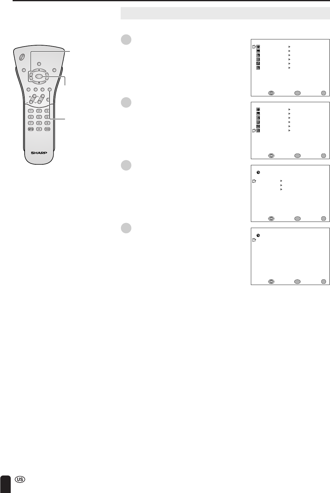
40
CHVOL
POWER
ENTER
DISPLAY
MUTE
SLEEP PIC. FLIP
BRIGHT TV/VIDEO MENU
FLASH-
BACK
Adjusting LANGUAGE Settings
The language for the On-Screen Display can be ENGLISH, SPANISH or FRENCH.
1Press MENU to display the MENU
screen.
2Press a/b to move the cursor to
“SET UP”, and press ENTER.
3Press a/b to move the cursor to
“LANGUAGE”, and press ENTER.
4Press a/b to select the language, and
press ENTER.
ADJUSTMENTS (Continued)
ENTER
MENU
a/b
M
ENU
SLEEP T I
M
ER
V IDEO ADJUST
PRESET
CLOSED CAPT ION
V–CHIP BLOCK
SET UP
SELECT : ENTER: EXIT:
ENTER
MENU
M
ENU
SLEEP T I
M
ER
V IDEO ADJUST
PRESET
CLOSED CAPT ION
V–CHIP BLOCK
SET UP
SELECT : ENTER: EXIT:
ENTER
MENU
BLUE SCREEN [OFF]
LANGUAGE
SELECT : EXIT:
ENTER
RETURN SET UP
CH–SETT I NG
ENTER:
MENU
CLOCK
LANGUAGE
ENGL I SH
ESPAÑOL
FRANCA I S
SELECT : EXIT:
MENU
RETURN
ENTER:
ENTER

ENGLISH
41
ADJUSTMENTS (Continued)
EXIT:
RETURN
P I CTURE
50 –+
ADJUST :
SELECT :
MENU
PICTURE [ 50]
TINT
COLOR
BLACK LEVEL
SHARPNESS
SELECT : ENTER: EXIT:
V I DEO ADJUST ( TV)
RETURN
[ 0]
[ 0]
[ 0]
[ 0]
RED-BLUE [ 0]
GREEN [ 0]
RESET
ENTER
MENU
M
ENU
SLEEP T I
M
ER
V IDEO ADJUST
PRESET
CLOSED CAPT ION
V–CHIP BLOCK
SET UP
SELECT : ENTER: EXIT:
ENTER
MENU
M
ENU
SLEEP T I
M
ER
V IDEO ADJUST
PRESET
CLOSED CAPT ION
V–CHIP BLOCK
SET UP
SELECT : ENTER: EXIT:
ENTER
MENU
CHVOL
POWER
ENTER
DISPLAY
MUTE
SLEEP PIC. FLIP
BRIGHT TV/VIDEO MENU
FLASH-
BACK
ENTER/
a/b/c/d
MENU
Adjusting VIDEO ADJUST Settings
Video adjustments have different selection items depending on TV mode or AV
mode (signal from an external device). (See page 42.)
1Press MENU to display the MENU
screen.
2Press a/b to move the cursor to
“VIDEO ADJUST”, and press ENTER.
3Press a/b to move the cursor to the
desired item, and press ENTER.
4Press c/d to change the setting.
Note:
•See page 42 for the settings.
5Press MENU to return to the main
screen.
42
ADJUSTMENTS (Continued)
Adjusting VIDEO ADJUST Settings (Continued)
TV mode
Selected item Press cPress d
PICTURE Decrease contrast Increase contrast
TINT Toward purple Toward green
COLOR Lower color intensity Higher color intensity
BLACK LEVEL Less brightness More brightness
SHARPNESS Soft picture Sharp picture
RED-BLUE Stronger red Stronger blue
GREEN Weaker green Stronger green
AV mode
Selected item Press cPress d
PICTURE Decrease contrast Increase contrast
TINT Toward purple Toward green
COLOR Lower color intensity Higher color intensity
BLACK LEVEL Less brightness More brightness
SHARPNESS Soft picture Sharp picture
RED-BLUE Stronger red Stronger blue
GREEN Weaker green Stronger green
Note:
•VIDEO ADJUST settings displayed in magenta cannot be selected.
•Selecting “RESET” will return all settings to the factory settings. (See page 41.)

ENGLISH
43
ADJUSTMENTS (Continued)
SET UP
■EZ SETUP
When you move to an area with different broadcasting signals, the set will
automatically memorize the channel number and time. Refer to pages 22 and
23 for more information on EZ SETUP.
■SETTING THE AIR/CABLE
It is necessary to set the receiving mode to AIR or CABLE channels to receive
locally broadcast TV programs.
1Switch the screen to TV mode and press
MENU to display the MENU screen.
2Press a/b to move the cursor to
“SET UP”, and press ENTER.
3Press a/b to move the cursor to
“CH-SETTING”, and press ENTER.
•When the screen is not in TV mode,
“CH-SETTING” is displayed in magenta
and not available.
4Press c/d to move the cursor to
“AIR/CABLE”, and press ENTER.
5Press c/d to move the cursor to the
desired mode, and press ENTER.
6Press MENU to return to the main
screen.
•Receivable channels of your TV set are:
AIR channels: CABLE channels:
VHF: 2 through 13 1 (HRC and IRC)
UHF: 14 through 69 2 through 125 (STD, HRC and IRC)
CHVOL
POWER
ENTER
DISPLAY
MUTE
SLEEP PIC. FLIP
BRIGHT TV/VIDEO MENU
FLASH-
BACK
ENTER/
a/b/c/d
MENU
CH–SETT ING
AI R/CABLE
EZ SETUP
CH SEARCH
CH
M
E
M
ORY
SELECT : ENTER: EXIT:
RETURN
ENTER
MENU
AIR/CABLE
SELECT : EXIT:
AIR
CABLE
MENU
ENTER:
RETURN
ENTER
M
ENU
SLEEP T I
M
ER
V IDEO ADJUST
PRESET
CLOSED CAPT ION
V–CHIP BLOCK
SET UP
SELECT : ENTER: EXIT:
ENTER
MENU
BLUE SCREEN [OFF]
LANGUAGE
SELECT : EXIT:
ENTER
RETURN SET UP
CH–SETT I NG
ENTER:
MENU
CLOCK
44
ADJUSTMENTS (Continued)
CHVOL
POWER
ENTER
DISPLAY
MUTE
SLEEP PIC. FLIP
BRIGHT TV/VIDEO MENU
FLASH-
BACK
ENTER/
a/b/c/d
MENU
CH–SETT ING
AI R/CABLE
CH SEARCH
CH
M
E
M
ORY
RETURN
EZ SETUP
START: EXIT:
CH SEARCH
AIR 2
MENU
M
ENU
SLEEP T I
M
ER
V IDEO ADJUST
PRESET
CLOSED CAPT ION
V–CHIP BLOCK
SET UP
BLUE SCREEN [OFF]
LANGUAGE
RETURN SET UP
CH–SETT I NG
CLOCK
Press
d
to add channel 2
to the TV memory
Press
c
to erase channel 2
from the TV memory
CH–SETT ING
AI R/CABLE
CH SEARCH
CH
M
E
M
ORY
RETURN
EZ SETUP
TO ADD: EXIT:
CH MEMORY
AIR 2
MENU
TO ERASE : EXIT:
CH MEMORY
AIR 2
MENU
CHVOL
POWER
ENTER
DISPLAY
MUTE
SLEEP PIC. FLIP
BRIGHT TV/VIDEO MENU
FLASH-
BACK
ENTER/
a/b/c/d
Channel
Select
MENU
SET UP (Continued)
■Saving broadcast TV channels in the memory
1Press MENU to display the MENU
screen, press a/b to move the cursor
to “SET UP”, and press ENTER.
2Press a/b to move the cursor to
“CH-SETTING”, and press ENTER.
3Press a/b to move the cursor to
“CH SEARCH”, and press ENTER.
4Press d. The tuner will search through
all available channels in your area and
add them to the TV memory.
•To interrupt CH SEARCH, press c. CH
SEARCH will stop at the current channel
and will not add any higher channels.
5Press MENU to exit.
■Adding weak or additional channels or erasing unwanted channels from
TV memory
1Press MENU to display the MENU
screen, press a/b to move the cursor
to “SET UP”, and press ENTER.
2Press a/b to move the cursor to
“CH-SETTING”, and press ENTER.
3Press a/b to move the cursor to
“CH MEMORY”, and press ENTER.
4Use a/b or Channel Select to select
each desired channel to add or erase.
5Press d to add the channel to the TV
memory or press c to erase the
channel from the TV memory.
6Press MENU to exit.
•If CH SEARCH is performed again, the
previously memorized channels will be lost.

ENGLISH
45
ADJUSTMENTS (Continued)
CHVOL
POWER
ENTER
DISPLAY
MUTE
SLEEP PIC. FLIP
BRIGHT TV/VIDEO MENU
FLASH-
BACK
ENTER/
a/b/c/d
MENU
M
ENU
SLEEP T I
M
ER
V IDEO ADJUST
PRESET
CLOSED CAPT ION
V–CHIP BLOCK
SET UP
SELECT : ENTER: EXIT:
ENTER
MENU
BLUE SCREEN [OFF]
LANGUAGE
SELECT : EXIT:
ENTER
RETURN SET UP
CH–SETT I NG
ENTER:
MENU
CLOCK
BLUE SCREEN [ O N ]
LANGUAGE
SELECT : EXIT:
ENTER
RETURN SET UP
CH–SETT I NG
ENTER:
MENU
CLOCK
Adjusting BLUE SCREEN Settings
■BLUE SCREEN
This function automatically turns the screen blue if no broadcast signal is
received.
1Press MENU to display the MENU
screen.
2Press a/b to move the cursor to
“SET UP”, and press ENTER.
3Press a/b to move the cursor to
“BLUE SCREEN”, and press ENTER.
4Press c/d to select “ON” or “OFF”, and
press ENTER.
5Press MENU to return to the main
screen.
Note:
•When received signals are weak or interfered with by some other signals, the BLUE
SCREEN function may be activated. To watch the TV under such conditions, set
“BLUE SCREEN” to “OFF”.
•The BLUE SCREEN function is activated when AV1, AV2, AV3 or AV4 input mode is
selected with no signal being input.
46
ADJUSTMENTS (Continued)
CC/TEXT [OFF]
SELECT : EXIT:
RETURN CLOSED CAPT ION
ENTER:
ENTER
MENU
CC/TEXT [CC1]
EXIT:
RETURN CLOSED CAPT ION
ENTER:
ENTER
ADJUST :
MENU
M
ENU
SLEEP T I
M
ER
V IDEO ADJUST
PRESET
CLOSED CAPT ION
V–CHIP BLOCK
SET UP
SELECT : ENTER: EXIT:
ENTER
MENU
CHVOL
POWER
ENTER
DISPLAY
MUTE
SLEEP PIC. FLIP
BRIGHT TV/VIDEO MENU
FLASH-
BACK
ENTER/
a/b/c/d
MUTE
MENU
Adjusting CLOSED CAPTION Settings
■SETTING CLOSED CAPTION
•This TV set is equipped with an internal Closed
Caption decoder. “CLOSED CAPTION” is a
system which allows conversations, narration, and
sound effects in TV programs and home videos to
be viewed as captions on the TV screen (see the
illustration).
•Not all programs and videos will offer closed
captioning. Please look for the “” symbol to
ensure that captions will be shown.
•The Closed Caption broadcasts can be viewed in two modes: CAPTION and
TEXT. For each mode, two channels are available: CH1 and CH2.
The CAPTION mode shows subscripts of dialogs and commentaries of TV
dramas and news programs while allowing a clear view of the picture.
The TEXT mode displays various information over the picture (such as TV
program schedules and weather forecasts, etc.) that is independent of the TV
programs.
Setting the CLOSED CAPTION on the
MENU screen
1Press MENU to display the MENU
screen.
2Press a/b to move the cursor to
“CLOSED CAPTION” , and press
ENTER.
3Press ENTER for the CLOSED
CAPTION setting.
4Press c/d to change the CLOSED
CAPTION setting, and press ENTER.
CC1 CC2OFF T1 T2
Note:
•CC1: CAPTION mode for CH1 data
CC2: CAPTION mode for CH2 data
T1: TEXT mode for CH1 data
T2: TEXT mode for CH2 data
5Press MENU to return to the main
screen.
Note:
•Color characters for closed captioning are not
supported with this TV. Characters are white only.
•If a broadcast contains Closed Caption data and
MUTE is pressed, the TV set enters CAPTION
mode automatically. Pressing MUTE again will
return the TV set to its previous condition.
•Closed Caption may malfunction (white blocks,
strange characters, etc.) if signal conditions are
poor or if there are problems at the broadcast
source. This does not necessarily indicate a
problem with your TV set.
•If any button is pressed to call up the On-Screen
Display while viewing a Closed Caption broad-
cast, the closed captions will disappear momen-
tarily.
•If no TEXT broadcast is being received while
viewing in the TEXT mode, the screen may
become dark and blank for some programs.
Should this occur, switch the CLOSED CAPTION
mode to “OFF”.
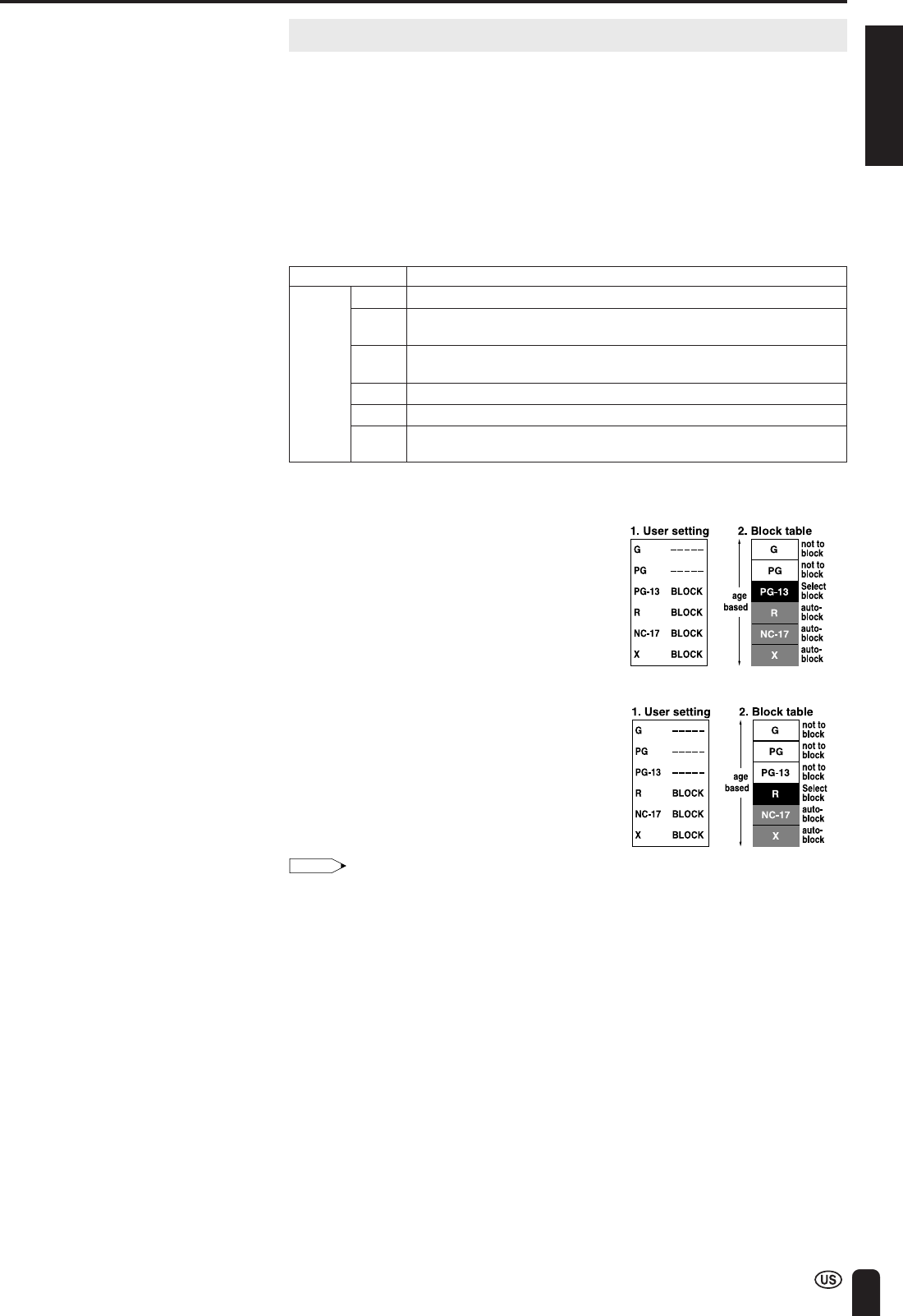
ENGLISH
47
ADJUSTMENTS (Continued)
Adjusting V-CHIP Settings
■V-CHIP
•This function allows TV programs to be restricted and TV usage to be
controlled based on FCC data. It prevents children from watching violent or
sexual scenes that may be harmful.
•Restriction of TV programs includes two ratings that contain information about
the program: the MPAA rating and the TV Parental Guidelines. The MPAA
rating is restricted by age. TV Parental Guidelines are restricted by age and
content.
•Since a TV program may use either the MPAA rating or the TV Guidelines,
both should be adjusted for complete control.
[1] MPAA RATING
RATING Description
G GENERAL AUDIENCES. All ages admitted.
PG PARENTAL GUIDANCE SUGGESTED. Some material may not be suitable
for children.
PG-13 PARENTS STRONGLY CAUTIONED. Some material may be
inappropriate for children under 13.
R RESTRICTED. Under 17 requires accompanying parent or adult guardian.
NC-17 NO ONE 17 AND UNDER ADMITTED.
X X is an older rating that is unified with NC-17 but may be encoded in the
data of older movies.:
MPAA RATING
Example 1:
When PG-13 in the age-based rating is
blocked, this will also automatically block
the higher ratings R, NC-17 and X.
Example 2:
When R in the age-based rating is
blocked, this will also automatically block
the higher ratings NC-17 and X.
Note:
•The MPAA rating is only age-based.
⇑
age
based
⇓
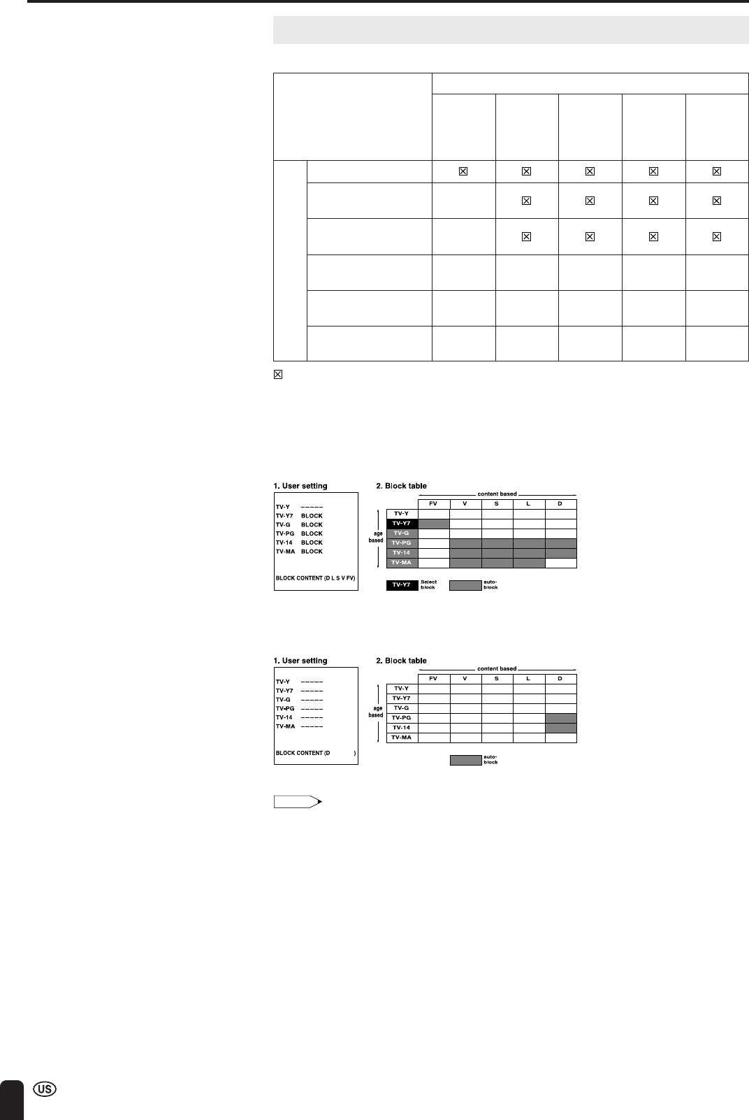
48
ADJUSTMENTS (Continued)
⇐ content based ⇒
FV V S L D
(Fantasy (Violence) (Sexual (Adult (Sexually
Violence) Situation) Language) Suggestive
Dialog)
TV-Y (All children)
TV-Y7 (Direct to Older ✕
Children)
TV-G (General X
Audience)
TV-PG (Parental ✕✕✕✕
Guidance Suggested) xxx
TV-14 (Parents ✕✕✕✕
Strongly Cautioned) X
TV-MA (Mature X✕✕✕
Audience Only)
RATING
⇑
age
based
⇓
Adjusting V-CHIP Settings (Continued)
[2] TV PARENTAL GUIDELINES
: The content rating can be set, but this rating is not normally broadcast by TV stations.
✕: The content rating can be set.
TV PARENTAL GUIDELINES
Example 1:
When TV-Y7 in the age-based rating is set to “BLOCK”, this will automatically block the higher
ratings: TV-G, TV-PG, TV-14 and TV-MA. In addition, D, L, S, V and FV in CONTENT are
automatically blocked unless you manually set “BLOCK CONTENT”.
Example 2:
When no item in the age-based rating is blocked, D in the content-based rating will be automatically
blocked.
Note:
•Age-based ratings can be modified by the content-based ratings, but only in the combina-
tions indicated by an X in the table above.
•Choosing a lower age-based rating blocks the higher age-based ratings regardless of
content rating settings.
•If you set “TV-Y” and “TV-Y7” to “BLOCK”, CONTENT will display all items.
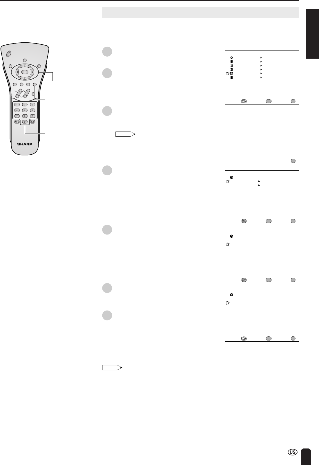
ENGLISH
49
ADJUSTMENTS (Continued)
INPUT SECRET NO.
– – – –
EXIT:
MENU
M
PAA
TV GUIDELINES
STATUS
SELECT : EXIT:
RETURN V–CHIP BLOCK
[OFF]
ENTER:
ENTER
MENU
M
PAA
G [ –––––]
EXIT:
RETURN
PG [ BLOCK ]
PG–13 [BLOCK]
R [BLOCK]
NC–17 [ BLOCK]
X [BLOCK]
ENTER:
ENTER
ADJUST :
MENU
M
PAA
G [ –––––]
EXIT:
RETURN
PG [ –––––]
PG–13 [–––––]
R [ –––––]
NC–17 [ –––––]
X [ –––––]
ENTER:
ENTER
SELECT :
MENU
ENTER/
a/b/c/d
Channel
Select
CHVOL
POWER
ENTER
DISPLAY
MUTE
SLEEP PIC. FLIP
BRIGHT TV/VIDEO MENU
FLASH-
BACK
MENU
M
ENU
SLEEP T I
M
ER
V IDEO ADJUST
PRESET
CLOSED CAPT ION
V–CHIP BLOCK
SET UP
SELECT : ENTER: EXIT:
ENTER
MENU
Adjusting V-CHIP Settings (Continued)
■SETTING V-CHIP
[1] MPAA RATING
1Press MENU to display the MENU
screen.
2Press a/b to move the cursor to
“V-CHIP BLOCK”, and press ENTER.
3“INPUT SECRET NO.” will be displayed.
Input the 4-digit secret number by using
Channel Select, and press ENTER.
Note:
•When you input the secret number for the
first time, press ENTER to register.
Otherwise, continue to step 4.
4Press a/b to move the cursor to
“MPAA”, and press ENTER.
5Press a/b to move the cursor to “PG”,
and press ENTER.
6Press c/d to select “BLOCK”, and
press ENTER. If you set “PG” to
“BLOCK”, “PG-13”, “R”, “NC-17” and “X”
are automatically blocked.
7Press MENU to return to the main
screen.
Note:
•If you set “G” to “BLOCK”, all ratings are automatically blocked.
•If you set “X” to “BLOCK”, “G”, “PG”, “PG-13”, “R” and “NC-17” are not blocked.

50
ADJUSTMENTS (Continued)
CHVOL
POWER
ENTER
DISPLAY
MUTE
SLEEP PIC. FLIP
BRIGHT TV/VIDEO MENU
FLASH-
BACK
ENTER/
a/b/c/d
MENU
M
PAA
TV GUIDELINES
STATUS
SELECT : EXIT:
RETURN V–CHIP BLOCK
[OFF]
ENTER:
ENTER
MENU
TV GUIDEL INES
TV–Y [ –––––]
EXIT:
BLOCK CONTENT
[D L S V FV ]
RETURN
TV–Y7 [BLOCK ]
TV–G [BLOCK ]
TV–PG [BLOCK]
TV–14 [BLOCK]
TV–
M
A [BLOCK]
ENTER:
ENTER
ADJUST :
MENU
TV GUIDEL INES
TV–Y [ –––––]
SELECT : EXIT:
BLOCK CONTENT
[ ]
RETURN
TV–Y7 [–––––]
TV–G [ –––––]
TV–PG [–––––]
TV–14 [–––––]
TV–
M
A [ –––––]
ENTER:
ENTER
MENU
Adjusting V-CHIP Settings (Continued)
[2] TV GUIDELINES
● Setting TV GUIDELINES
1Repeat steps 1 to 3 of [1] MPAA
RATING. (See page 49.)
2Press a/b to move the cursor to
“TV GUIDELINES”, and press ENTER.
3Press a/b to move the cursor to
“TV-Y7”, and press ENTER.
4Press c/d to select “BLOCK”, and
press ENTER. If you set “TV-Y7” to
“BLOCK”, “TV-G”, “TV-PG”, “TV-14” and
“TV-MA” are automatically blocked. In
addition, “D”, “L”, “S”, “V” and “FV” in
CONTENT are automatically blocked.
5Press MENU to return to the main
screen.

ENGLISH
51
ADJUSTMENTS (Continued)
CHVOL
POWER
ENTER
DISPLAY
MUTE
SLEEP PIC. FLIP
BRIGHT TV/VIDEO MENU
FLASH-
BACK
ENTER/
a/b/c/d
MENU
TV GUIDEL INES
TV–Y [ –––––]
SELECT : EXIT:
BLOCK CONTENT
[ ]
RETURN
TV–Y7 [–––––]
TV–G [ –––––]
TV–PG [–––––]
TV–14 [–––––]
TV–
M
A [ –––––]
ENTER:
ENTER
MENU
D [ –––––]
EXIT:
RETURN
L [ BLOCK ]
S [ –––––]
V [ –––––]
FV [–––––]
BLOCK CONTENT
ENTER:
ENTER
ADJUST :
MENU
M
PAA
TV GUIDELINES
STATUS
SELECT : EXIT:
RETURN V–CHIP BLOCK
[OFF]
ENTER:
ENTER
MENU
D [ –––––]
SELECT : EXIT:
RETURN
L [ –––––]
S [ –––––]
V [ –––––]
FV [–––––]
BLOCK CONTENT
ENTER:
ENTER
MENU
Adjusting V-CHIP Settings (Continued)
■Setting BLOCK CONTENT
1Repeat steps 1 to 3 of [1] MPAA
RATING. (See page 49.)
2Press a/b to move the cursor to
“TV GUIDELINES”, and press ENTER.
3Press a/b to move the cursor to
“BLOCK CONTENT”, and press ENTER.
4Press a/b to move the cursor to the
desired item, and press ENTER.
5Press c/d to select “BLOCK” or “-----”
(unblock), and press ENTER.
6Press MENU to return to the main
screen.
Note:
•If you set “TV-14” to “BLOCK”, “TV-MA” is automatically blocked. Contents “D”, “L”, “S” and
“V” are automatically blocked by X in the table on page 48.
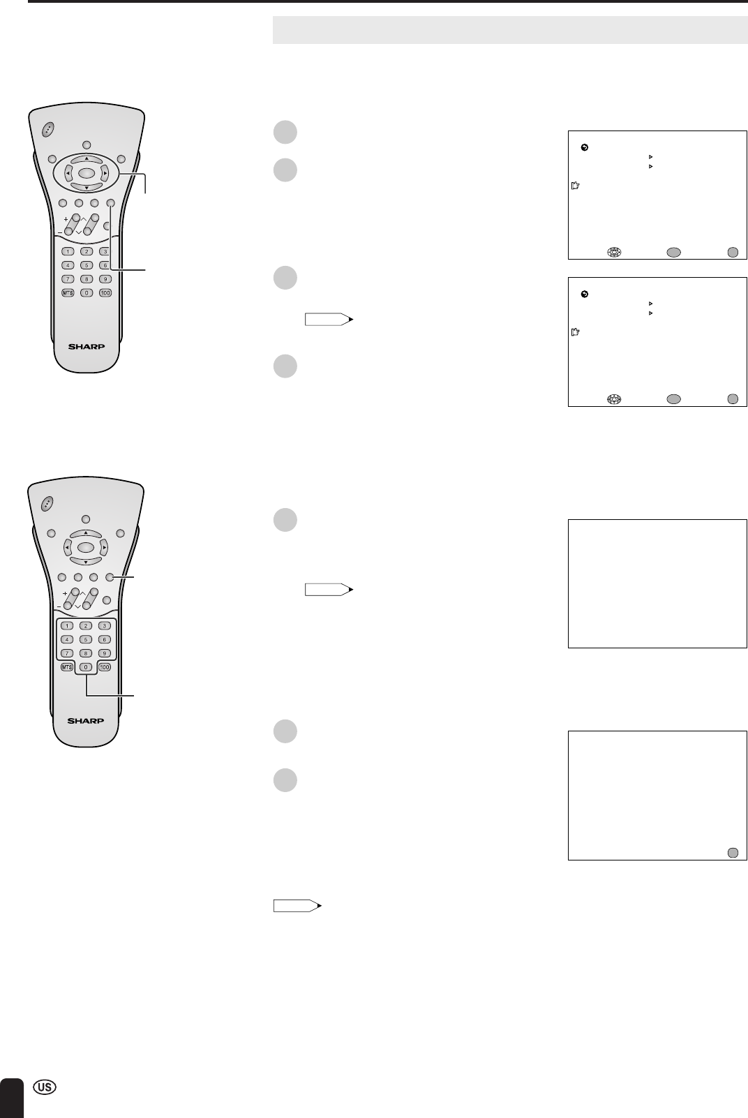
52
ADJUSTMENTS (Continued)
CHVOL
POWER
ENTER
DISPLAY
MUTE
SLEEP PIC. FLIP
BRIGHT TV/VIDEO MENU
FLASH-
BACK
ENTER/
a/b/c/d
MENU
M
PAA
TV GUIDELINES
STATUS
ENTER: EXIT:
RETURN V–CHIP BLOCK
[ON ]
ENTER:
ENTER
MENU
ADJUST :
M
PAA
TV GUIDELINES
STATUS
SELECT : EXIT:
RETURN V–CHIP BLOCK
[OFF]
ENTER:
ENTER
MENU
V–CHIP HAS BEEN ACT IVATED
TV–Y
INPUT SECRET NO.
– – – –
EXIT:
MENU
CHVOL
POWER
ENTER
DISPLAY
MUTE
SLEEP PIC. FLIP
BRIGHT TV/VIDEO MENU
FLASH-
BACK
MENU
Channel
Select
Adjusting V-CHIP Settings (Continued)
[3] ACTIVATING V-CHIP BLOCK
● Setting STATUS
You can activate V-CHIP BLOCK after setting [1] MPAA RATING and/or [2]
TV GUIDELINES.
1Repeat steps 1 to 3 of [1] MPAA
RATING. (See page 49.)
2Press a/b to move the cursor to
“STATUS”, and press ENTER.
3Press c/d to set “STATUS” to “ON”,
and press ENTER.
Note:
•If “STATUS” is set to “OFF”, “V-CHIP
BLOCK” will not be activated.
4Press MENU to return to the main
screen.
[4] CANCELING THE V-CHIP BLOCK SCREEN WHILE V-CHIP BLOCK IS
ACTIVATED
1“V-CHIP HAS BEEN ACTIVATED”
appears if you watch a program with the
same Program Rating data you
configured.
Note:
•“V-CHIP HAS BEEN ACTIVATED” will not
be displayed if “STATUS” is not configured
to “ON”.
•Since the V-CHIP setting is performed
using wireless communication, in order to
be sure that this setting is performed
correctly, perform it with the Wireless
Center nearby so that you can confirm the
video signal is correctly received.
2Press MENU to display “INPUT
SECRET NO.”
3Input the 4-digit secret number by using
Channel Select; V-CHIP BLOCK is
temporarily canceled. If you input an
incorrect secret number, “SECRET NO.
IS INCORRECT” is displayed. In this
case, input the correct secret number.
Note:
•If you turn the power on from off, V-CHIP BLOCK will be activated again.
•If you select “V-CHIP BLOCK” again by using MENU, V-CHIP BLOCK will be turned on
again.
•Usually when there are no problems with the reception, the V-CHIP information is indicated
in yellow characters against a blue background, but when the reception conditions are
unstable, the background and the characters may not always be indicated correctly in
color. (The background may consist of a 7-color striped image while the characters are
displayed in white.)
Should such a case occur, even when pressing the “MENU” button on the remote control,
the “INPUT SECRET NO.” screen is not displayed, making it impossible to input a secret
number. Therefore, perform this operation only after first receiving normal motion picture
on the screen.
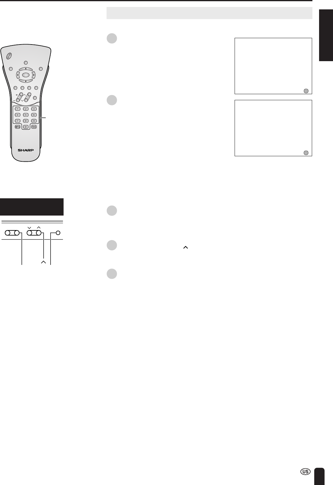
ENGLISH
53
ADJUSTMENTS (Continued)
CHVOL
POWER
ENTER
DISPLAY
MUTE
SLEEP PIC. FLIP
BRIGHT TV/VIDEO MENU
FLASH-
BACK
INPUT SECRET NO.
– – – –
EXIT:
MENU
INPUT SECRET NO.
* * * *
EXIT:
MENU
Channel
Select
CHVOL MENU
-
+
VOL (+)
CH ( )
MENU
Adjusting V-CHIP Settings (Continued)
[5] CHANGING V-CHIP BLOCK SETTINGS
1Repeat steps 1 to 2 of [1] MPAA
RATING, then “INPUT SECRET NO.”
will be displayed.
2Input the 4-digit secret number by using
Channel Select; the V-CHIP select
mode will be displayed. Set V-CHIP
BLOCK again.
[6] CHANGING OR CLEARING THE SECRET NUMBER
If you forget the secret number, clear the secret number as follows.
1Repeat steps 1 to 2 of [1] MPAA
RATING, or 1 to 2 of [4] CANCELING
THE V-CHIP BLOCK SCREEN WHILE
V-CHIP BLOCK IS ACTIVATED, then
“INPUT SECRET NO.” will be displayed.
2Press and hold both CH ( ) and VOL
(+) on the TV set simultaneously until
the message “INPUT SECRET NO.”
blinks.
3Press MENU to exit.
Upper control panel
of the TV main unit
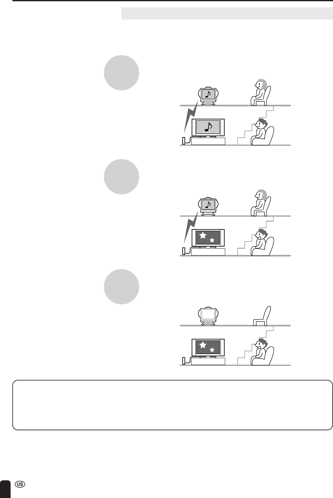
54
CONNECTION SYSTEM WITH VARIOUS WAYS OF BEING USED
Examples of Various Uses
The Wireless Center outputs pictures and sound via transmission to a television
receiver of this unit. Various manners of use are possible as it is possible to
connect your own main TV and the Wireless Center using a cable.
How the Wireless Center is used
It is possible for the same pictures and programs to be watched separately at
different locations.
It is also possible for separate pictures and programs to be enjoyed by one person
using a television on a second floor while another person is watching on a main TV
in a living room.
Even if the power supply of the Wireless Center is turned off, pictures and sound
can be received by the main TV connected to the output terminals (through) and
enjoyment is therefore possible even with a single television.
•An antenna through output, and AV-IN1 (through) output are provided at the LC-15L1U Wireless Center.
It is therefore possible for the system to be on without detriment to the advantages of using the main TV currently
being viewed. (Output also takes place when the power supply of the Wireless Center is turned off).
•Only three items of this equipment can be used in the same environment. If more are used, then it may not be
possible to watch television due to mutual interference.
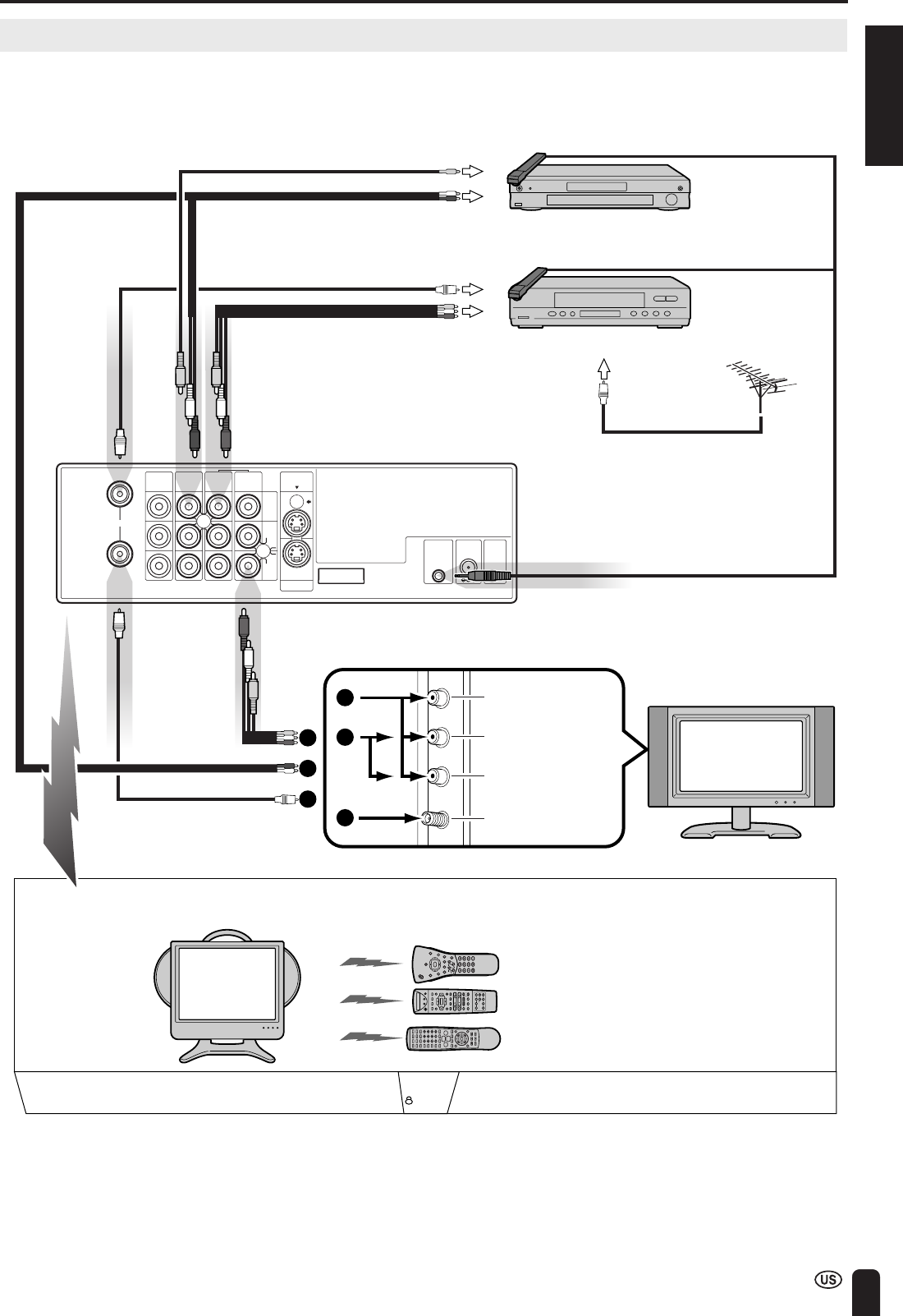
ENGLISH
55
CONNECTION SYSTEM WITH VARIOUS WAYS OF BEING USED (Continued)
Connecting System Chart of LC-15L1U
See pages 56 to 61 for the connection.
Video input terminal
Audio (L) input terminal
Audio (R) input terminal
Antenna input terminal
Main TV
(Large-size TV in a living room)
Antenna cable
Audio cord
Audio/Video cord
Video cord
To Video output
terminal
To Audio output
terminal
DVD player
VCR
Video controller
Video controller
Video controller
IN
OUT
AV-IN1AV-IN1AV-IN3
IR
OUT POWER
INPUT
DC12V
FACTORY
SERVICE
S-VIDEO
MONITOR
OUT
MONITOR
OUT
VIDEO
AUDIO
L
AUDIO
R
AV-IN2
/OUT
ANT.
Audio/Video cord
Wireless Center
(Rear view)
To Audio/Video
output terminal VHF/UHF antenna
To antenna
input terminal
Antenna cable
Antenna cable
To antenna
output terminal
1
1
2
3
2
3
TV main unit
(LC-15L1U)
Operation in a separate room
Equipped with
AV-IN4 system
(for playing games)
An equipment can be operated by transmitting remote control signals from
the equipment connected with the Wireless Center to the TV main unit.
Remote control for LC-15L1U
Remote control for DVD player
Remote control for VCR
TransmissionTransmission
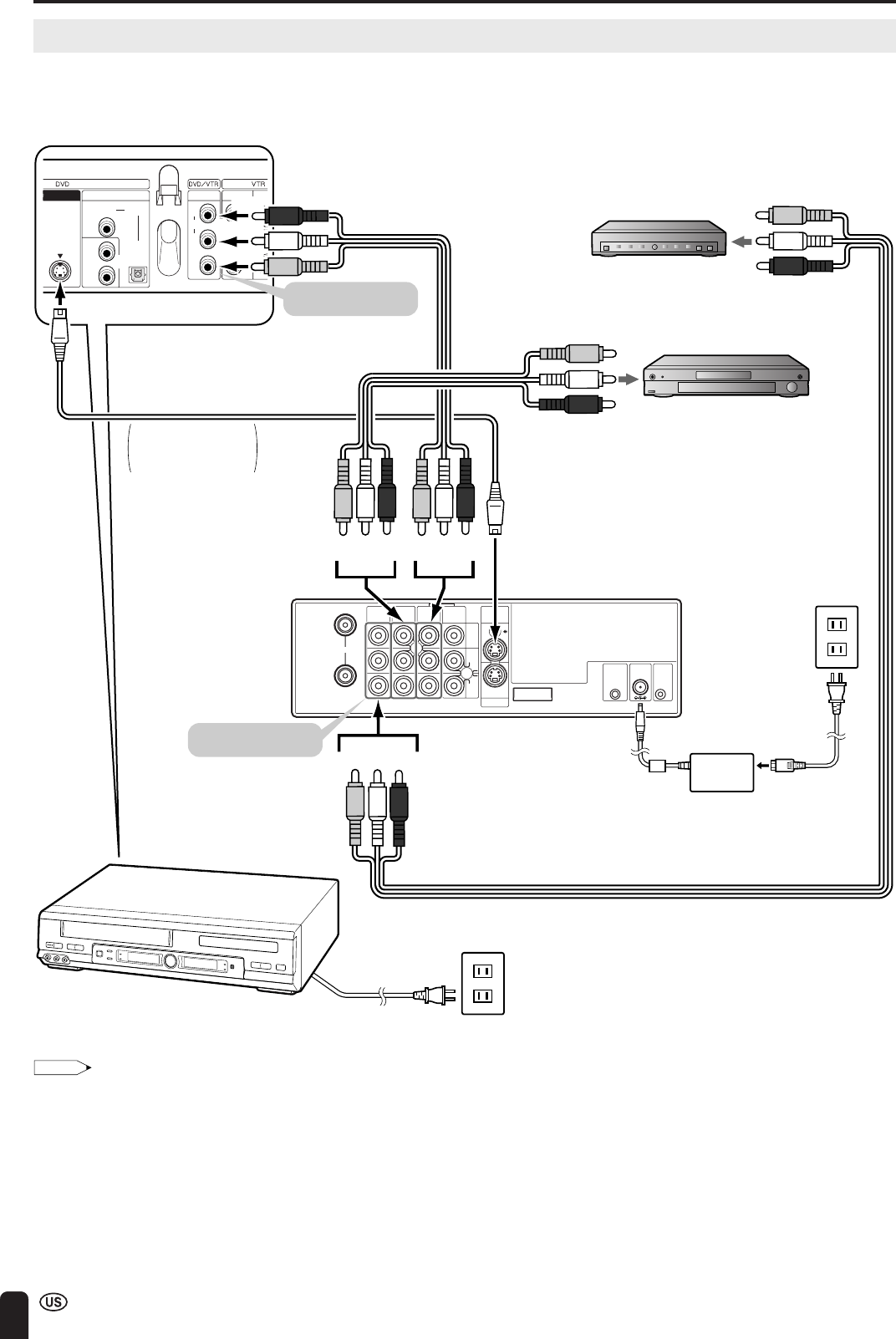
56
CONNECTION SYSTEM WITH VARIOUS WAYS OF BEING USED (Continued)
Method of Connecting External Equipment
■Place where Wireless Center is installed
Wireless Center should be placed on or beside video equipment. However, make sure that the Wireless Center is as far as
possible away from the antenna input terminal of a television or video equipment.
Note:
Regarding S-VIDEO terminal
•When connecting external equipment to AV-IN1 (Wireless Center) or to AV-IN4 (TV main unit) using both an Audio/Video cord and an S-video
cord, the input from the S-VIDEO terminal (S-Video cord) will have priority.
IN
OUT
AV-IN1AV-IN1AV-IN3
IR
OUT POWER
INPUT
DC12V
FACTORY
SERVICE
S-VIDEO
MONITOR
OUT
MONITOR
OUT
VIDEO
AUDIO
L
AUDIO
R
AV-IN2
/OUT
ANT.
AC wall
outlet
AC adapter AC cord
AC wall outlet
AC cord
AN
T
S-VIDEO
AUDIO
DIGITAL
OPTICAL
CO-
AXIAL
OUT IN
TV
R
L
AUDIO
VIDEO
R
L
AUDIO
VIDEO
R
L
DVD player
Decoder
To Audio/Video
output terminal
To AV-IN1
(S-VIDEO) terminal
To AV-IN2/OUT (AV)
terminal
To AV-IN3 (AV)
terminal
To S-VIDEO output terminal
To Audio/Video
output terminal
Rear
Front
VCR, etc.
Installation
example
To input/output terminal
(Red)
(White)
(Yellow)
(Red)
(White)
(Yellow)
(Red)
(White)
(Yellow)
(Red)
(White)
(Yellow)
Wireless Center
When connecting to
equipment with
an S-video terminal.
S-video cord
(commercially available)
Audio/Video cord
(commercially available)
Connect to the terminal
of the same color.
Connect to the terminal
of the same color.
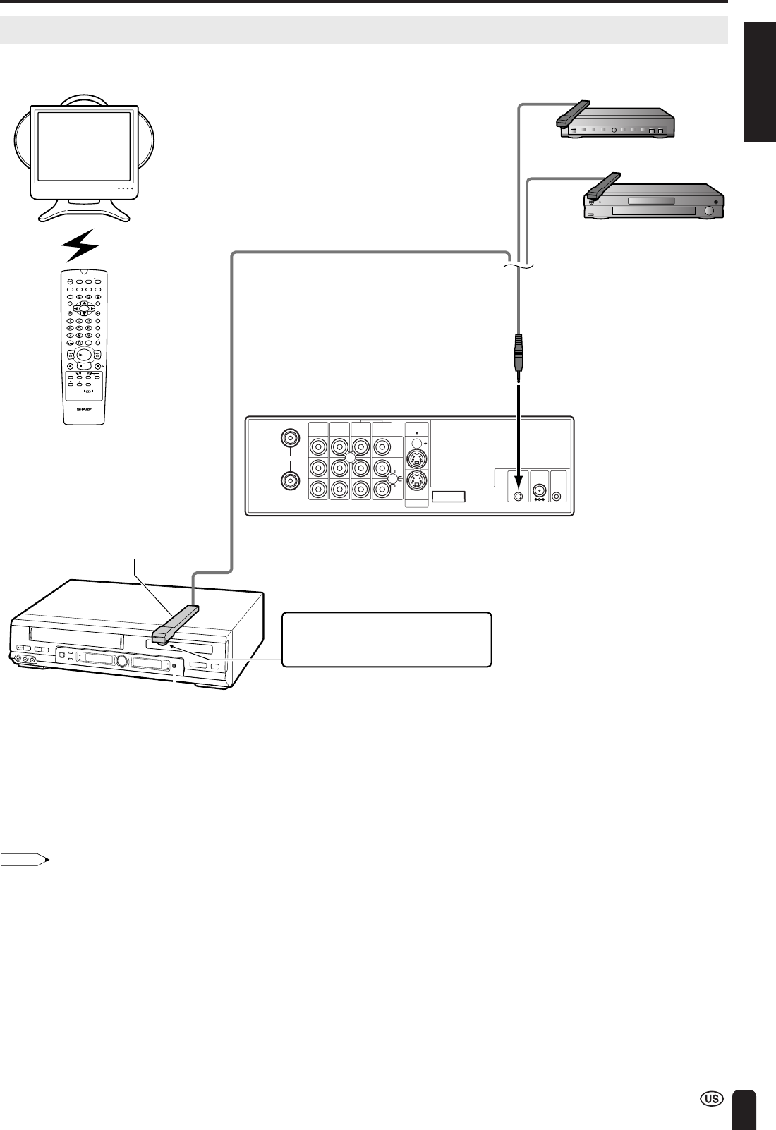
ENGLISH
57
CONNECTION SYSTEM WITH VARIOUS WAYS OF BEING USED (Continued)
IN
OUT
AV-IN1AV-IN1AV-IN3
IR
OUT POWER
INPUT
DC12V
FACTORY
SERVICE
S-VIDEO
MONITOR
OUT
MONITOR
OUT
VIDEO
AUDIO
L
AUDIO
R
AV-IN2
/OUT
ANT.
DVD player
Decoder
To Video controller terminal
Front
VCR etc.
Installation
example
(The video controller should be
fixed with the accessory tape once
the place where it is to be installed
has been decided.)
/
PLAY
STOP
OPEN/
CLOSE
OPERATE
VCR/DVD
SELECTOR VCR MENU
DVD SETUP
TAPE
SPEED
ON
SCREEN
TIMER
ON/OFF
TITLE
DVD MENU
DISPLAY
EJECT
FUNCTION
CONTROL
PROG/
REPEAT
CLEAR
RETURN
REV FWD
SET
ENTER
ZERO BACK
VCR DVDAM/PM
INPUT SELECT
PAUSE/STILL
REC
VCR/DVD COMBINATION
SLOW
CH
VCR DVD
SKIP
DPSS
AUDIO
OUTPUT
ZOOM
KARAOKE
SELECT
SKIP SEARCH
Wireless Center
The video controller is fixed so that
the transmitter of the video controller
faces the infrared receiver of the remote
control for the video equipment.
Video controller (supplied)
Infrared receiver of the remote
control (an example)
The remote control
for the external
equipment is used
for operating a
VCR or a DVD.
Method of Using the Video Controller
A maximum of two items of video equipment can be operated using the video controller.
■Cautions regarding installation of video controller
•The position of the infrared receiver of the remote control varies depending on the manufacturer or the type of the video
cassette recorder. Generally, it is a small round-shaped part close to the liquid crystal display portion.
•Make sure that the transmitter of the video controller is facing the infrared receiver of the remote control.
•When installing the video controller, try first to transmit remote control signals from the equipment connected with the
Wireless Center to the TV main unit to find a position where the connected equipment can be operated.
Note:
Regarding video controller
•Connect the VIDEO output terminal and AUDIO output terminals of equipment to play an image to AV-IN1/2/3 on the Wireless Center
respectively. After that, connect the video controller to the video controller terminal of Wireless Center.
•When installing video controller, make sure that this transmitter is facing the infrared receiver of the remote control for the connected
equipment. It is possible to operate a connected equipment by facing the remote control for the equipment connected to the Wireless
Center toward the infrared receiver of the remote control for the TV main unit and pressing the button.
•Depending on the external equipment that is connected, you may not be able to use the remote control to operate it, as its remote control
signal is different.
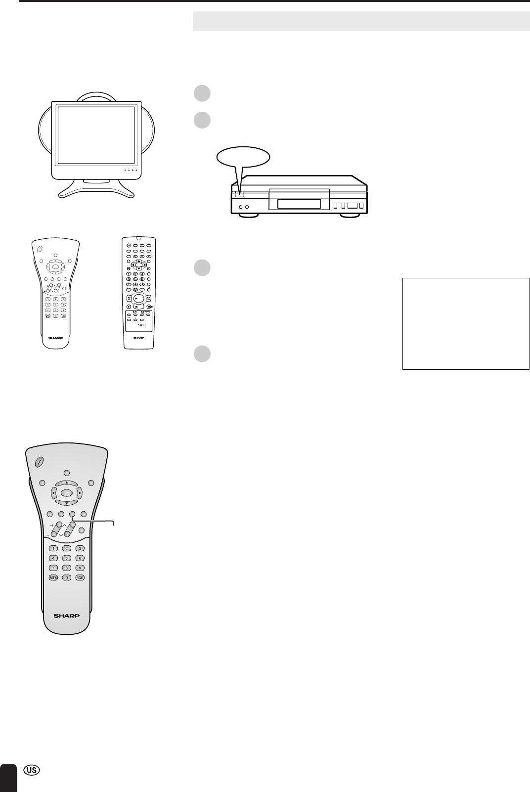
58
Watching Played Back Image from External Equipment
When watching played back images from external equipment, operations are
carried out such as switching over the input source using the remote control for the
TV main unit, and playing back and selecting channels using the remote control for
the external equipment.
1Turn on the power supply for Wireless
Center.
2Turn on the power supply for the
external equipment.
Power ON
•Regarding operating method, refer to
the operation manual for the
equipment.
3Press TV/VIDEO to select the video
input source being connected to.
4Make operations such as playing back
or selecting channels using the remote
control for the external equipment.
CONNECTION SYSTEM WITH VARIOUS WAYS OF BEING USED (Continued)
TV main unit
/
PLAY
STOP
OPEN/
CLOSE
OPERATE
VCR/ DVD
SELECTOR
VCR MENU
DVD SETUP
TAPE
SPEED
ON
SCREEN
TIMER
ON/OFF
TITLE
DVD MENU
DISPLAY
EJECT
FUNCTION
CONTROL
PROG/
REPEAT
CLEAR
RETURN
REV FWD
SET
ENTER
ZERO BACK
VCR DVDAM/PM
INPUT SELECT
PAUSE/STILL
REC
VCR/DVD COMBINATION
SLOW
CH
VCR DVD
SKIP
DPSS
AUDIO
OUTPUT
ZOOM
KARAOKE
SELECT
SKIP SEARCH
CHVOL
POWER
ENTER
DISPLAY
MUTE
SLEEP PIC. FLIP
BRIGHT TV/VIDEO MENU
FLASH-
BACK
AV1
The remote control
for the TV main
unit is used for
switching over the
input of the TV
main unit.
The remote control
for the external
equipment is used
for operating a
VCR or a DVD.
CHVOL
POWER
ENTER
DISPLAY
MUTE
SLEEP PIC. FLIP
BRIGHT TV/VIDEO MENU
FLASH-
BACK
TV/VIDEO
Example
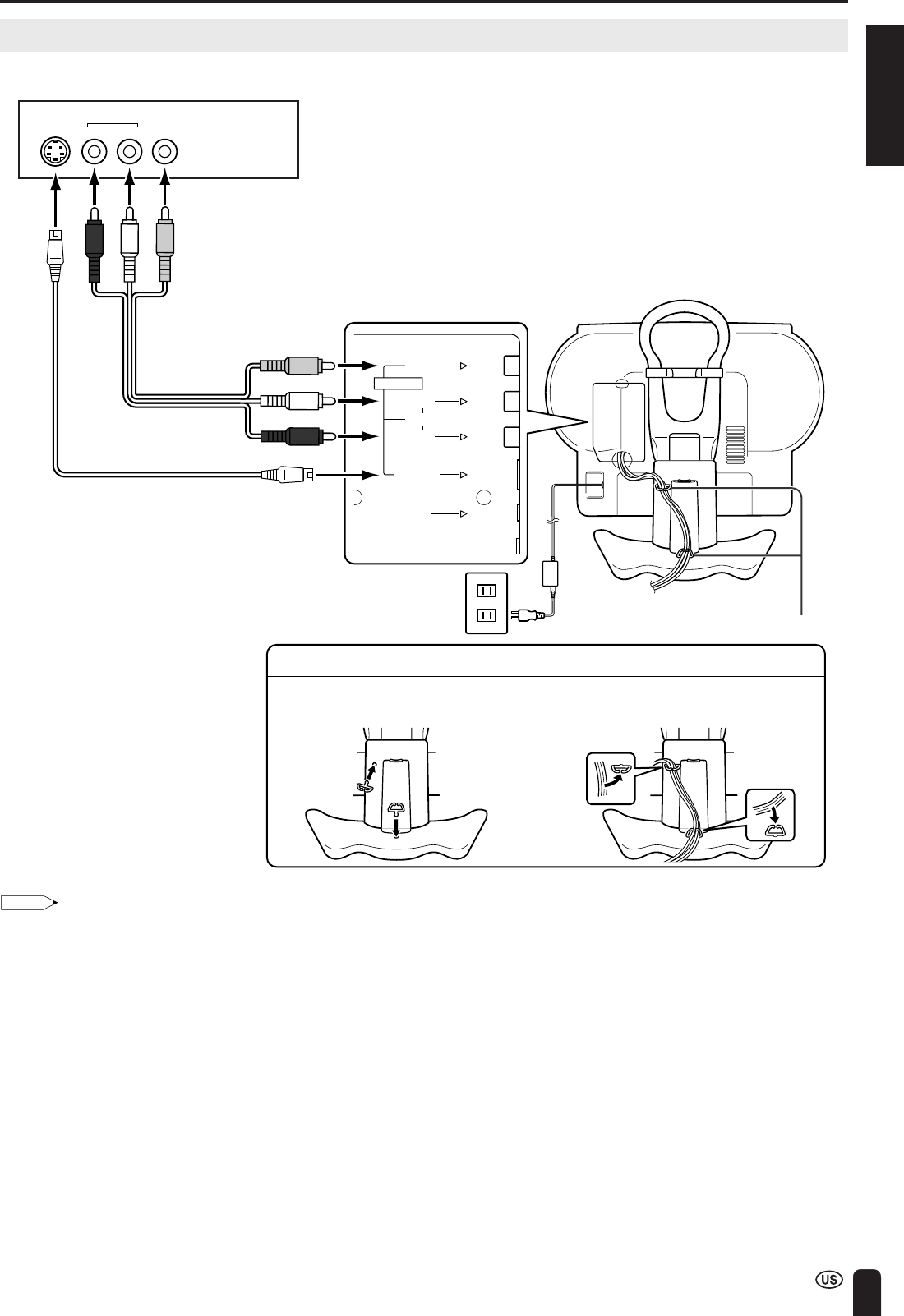
ENGLISH
59
CONNECTION SYSTEM WITH VARIOUS WAYS OF BEING USED (Continued)
VIDEOS-VIDEO
AUDIO
RL
How to Fix Cable Clamps
AUDIO
AV-IN4
VIDEO
S-VIDEO
L
R
HEAD
PHONE
(Red)
(Yellow)
(White)
(Red)
(White)
(Yellow)
Game system, VCR, DVD, etc.
Audio/Video cord
(commercially
available)
S-Video cord (commercially available)
Cable clamps
AC wall outlet
1Insert cable clamps into the hole for
the table stand.
2Cables are fitted in the cover of the table
stand and then fitted into the cable
clamps.
Note:
•Game devices must always be connected to the AV-IN4 terminal of the TV main unit. If a game device is connected to the Wireless Center,
you cannot enjoy the game comfortably because of a delay in the transmission of pictures and sound.
•When connecting external equipment to AV-IN4 using both an Audio/Video cord and an S-video cord, the input from the S-VIDEO terminal
(S-Video cord) will have priority.
•When signals from external equipment connected to the Wireless Center do not appear to be transmitted to the TV main unit properly,
connect the external equipment to the AV-IN4 terminal of the TV main unit.
Connecting a Home Video Game System, etc. (AV-IN4)
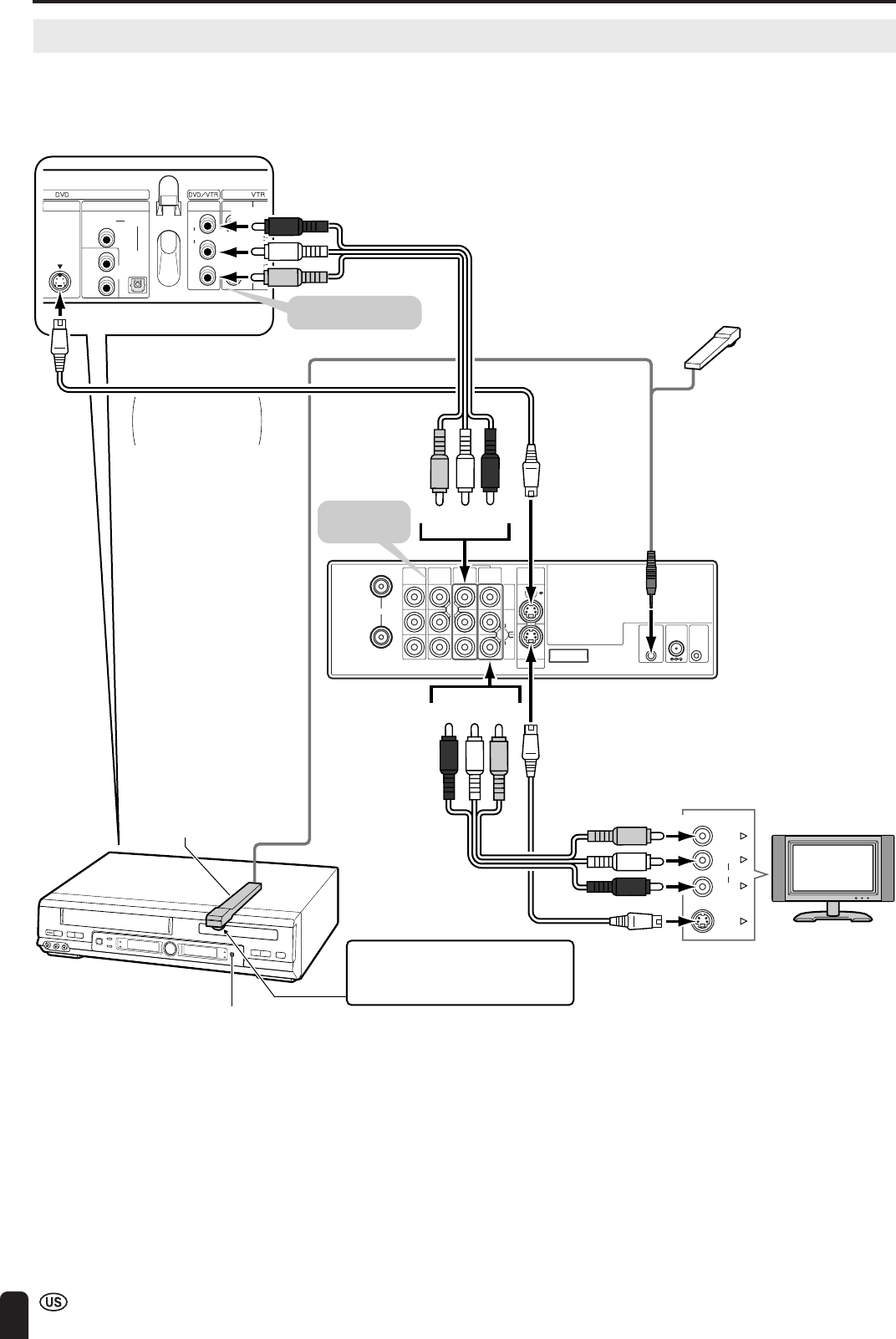
60
CONNECTION SYSTEM WITH VARIOUS WAYS OF BEING USED (Continued)
IN
OUT
AV-IN1AV-IN1AV-IN3
IR
OUT POWER
INPUT
DC12V
FACTORY
SERVICE
S-VIDEO
MONITOR
OUT
MONITOR
OUT
VIDEO
AUDIO
L
AUDIO
R
AV-IN2
/OUT
ANT.
Wireless Center
TV
VIDEO
L
R
S-VIDEO
AUDIO
AN
T
S-VIDEO
AUDIO
DIGITAL
OPTICAL
CO-
AXIAL
OUT IN
TV
R
L
AUDIO
VIDEO
R
L
AUDIO
VIDEO
R
L
To Video controller terminal
To AV-IN1 (S-VIDEO) terminal To MONITOR OUT
(S-VIDEO) terminal
To S-VIDEO output terminal
To Audio/Video
output terminal
Rear
Front
VCR etc.
Installation
example
(The video controller should be
fixed with the accessory tape
once the place where it is to be
installed has been decided.)
(Red)
(White)
(Yellow)
(Red)
(White)
(Yellow)
(Red)
(White)
(Yellow)
(Red)
(White)
(Yellow)
The video controller is fixed so that
the transmitter of the video controller
faces the infrared receiver of the remote
control for the video equipment.
Infrared receiver (an example)
Video controller (supplied)
When connecting to
equipment having
an S-video terminal.
S-video cord
(commercially available)
S-video cord
(commercially
available)
Audio/Video cord
(commercially available)
Audio/Video cord
(commercially available)
Connect to the terminal
of the same color.
To AV-IN1 (AV)
terminal
To MONITOR OUT
(AV) terminal
Connect to the
terminal of the
same color.
How to Use AV-IN1 Output
Since a video signal received at AV-IN1 terminal is output from the MONITOR OUT terminal, it is possible to enjoy pictures
and sounds from an external equipment (such as a VCR) connected to AV-IN1 input terminal on another television while
watching television on the TV main unit.
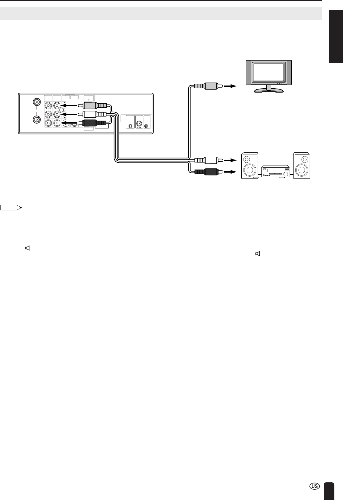
ENGLISH
61
CONNECTION SYSTEM WITH VARIOUS WAYS OF BEING USED (Continued)
IN
OUT
AV-IN1AV-IN1AV-IN3
IR
OUT POWER
INPUT
DC12V
FACTORY
SERVICE
S-VIDEO
MONITOR
OUT
MONITOR
OUT
VIDEO
AUDIO
L
AUDIO
R
AV-IN2
/OUT
ANT.
Wireless Center
When connecting to amplifier
or stereo, etc.
To Video input terminal
(Red)
(White)
(Yellow)
(Red)
(White)
(Yellow)
Audio/Video cord
(commercially available)
To AV-IN2/OUT terminal To audio input terminal
Monitor Output for Picture and Sound Output from AV-IN2/OUT Terminal
It is possible to output picture and sound being received by this unit from the AV-IN2/OUT terminal of the Wireless Center.
Note:
•Pictures and sound you have recorded cannot be used without permission from the copyright owner, other than for personal enjoyment.
•Transmission of pictures and sound from the Wireless Center to the TV main unit may take some time. For this reason, a picture that is
slightly delayed from the actual picture is displayed on the TV main unit. When recording pictures and sound on DVD or VCR while
watching the TV main unit, it will take about one second from pressing the picture record button on the remote control until actual picture
recording starts.
•When recording pictures or watching pictures on another device via the AV-IN2/OUT terminal of the Wireless Center, “AV2-IN/OUT” is set
to “OUT ”. (See page 39.)
If the television power supply is switched “off” using the remote control when the “AV2-IN/OUT” is set to “OUT ”, the power supply of the
Wireless Center is also put into a standby state, but output from the AV-IN2/OUT terminal continues. Therefore, if the main power supply of
the Wireless Center is switched off, output from the AV-IN2/OUT terminal stops.
* In the following cases, the power supply is in a standby state, but output from the AV-IN2/OUT terminal is possible.
•When television main power is “off”.
•When the power supply button of the remote control is “off”.
•Also in cases when communication is not possible due to some fault, output from the AV-IN2/OUT terminal is interrupted. For the
purpose of power conservation, when output from the AV-IN2/OUT terminal is not being used, it is recommended that the main power of
the Wireless Center be turned off.
* Even if the main power of the Wireless Center is turned off, the antenna output and AV-IN1 are output.
62
•Make sure the antenna cable is properly connected.
•Bad reception could be the problem.
TROUBLESHOOTING
Problem Check item Reference
pages
There is no
picture.
There is no
picture from
AV-IN1/4.
13
–
32
31
Sound Picture
•Make sure the AC adapter is properly inserted in the power outlet.
•Reception other than those of broadcasting stations can be consid-
ered.
•Make sure the input mode is set to TV.
•Make sure MAIN POWER of the TV main unit and Wireless Center
are on.
There is no
picture or
sound.
Picture
•Make sure the BLACK LEVEL is properly adjusted.
•The fluorescent lamp may have reached the end of service life.
•Make sure the S-VIDEO terminal has nothing connected.
There is no
sound.
•Make sure the volume is not set to minimum.
•Make sure the sound is not set to mute.
•Make sure that headphones are not connected.
There is no
picture or
sound, just
noise.
•Make sure the antenna cable is properly connected.
•Bad reception could be the problem.
Picture is not
clear.
Picture is light
or improperly
tinted.
•Check color adjustment.
The picture is
too dark.
•Press BRIGHT or set the BRIGHTNESS settings.
•Check PICTURE and BLACK LEVEL adjustment.
•The fluorescent lamp may have reached the end of service life.
Remote control does not work. •Check the batteries of the remote control.
•Make sure the remote sensor window is not under strong lighting.
41
65
56, 59, 60
33
33
16
12
–
12
–
41, 42
37
41
65
11
11
•The broadcasted EDS signal may be weak. Check the antenna.
•Carry out EZ SETUP, SETTING THE CLOCK again.
•If EDS signal is not sent, set the clock using the MANUAL CLOCK
Setting.
–
22-26
26
The clock (AUTO CLOCK) cannot
be set.
•The radio waves used by the product are at a high frequency, so
that there are features such as direct advance traveling, reflection,
refraction, diffraction, interference etc., similar to that of light. The
strength of the waves therefore varies depending on the location,
which may cause the pictures and sound to become unclear,
become wavy, or stop.
•Is the distance between the Wireless Center and TV main unit too
far? Use within a range that the radio waves can reach.
•Are you at a location that is particularly susceptible to electrical
noise?
•Set “DISTANCE” to “FAR”.
•The product utilizes wireless transmissions, so that fast moving
images may become distorted, but this is not a malfunction.
9
–
9
30
–
Blocks of noise appear on the
pictures. Sound becomes
interrupted.
■Before calling for repair services, make the following checks for possible remedies to the encountered symp-
toms.
TV set

ENGLISH
63
Problem Check item Reference
pages
9
•Are there any devices operating in the vicinity of the product such as
Bluetooth devices, or wireless LANs, or microwave ovens, etc. that
utilize the same frequency band (2.4 GHz) as the product?
•There are good and bad positions in terms of wave conditions with
regards to the influence of obstacles and reflectors. Try changing
the location of the TV main unit slightly.
•Is the video controller connected?
•Is the transmitter of the video controller facing the infrared receiver
of the remote control for the external equipment?
•Does the external equipment work when operating the remote
control by directly facing the external equipment? (If the external
equipment is still not working, it can be considered that the battery
of the remote control has run out.)
•Depending on the external equipment that is connected, you may
not be able to use the remote control to operate it.
9
57
57
–
–
TROUBLESHOOTING (Continued)
Pictures are suddenly stopped and
sound is interrupted.
Pictures and sound cannot be
received.
The external equipment does not
operate even though the remote
control is operated by facing toward
the TV main unit.
64
TROUBLESHOOTING (Continued)
Problem Check item
•The reception may be weak.
•The quality of the broadcast may also be bad.
•Make sure the antenna is facing the correct direction.
•Make sure the outside antenna has not been disconnected.
•Make sure the antenna is facing the correct direction.
•Broadcast waves may be reflected from adjacent mountains or buildings.
•There may be interference from automobiles, trains, high-voltage lines, neon
lights, etc.
•There may be interference between the antenna cable and power cable. Try
positioning them further apart.
•Is the unit receiving interference from other devices?
Transmission antennas of radio broadcasting stations and transmission antennas
of amateur radios and cellular phones may also cause interference.
•Use the unit as far apart as possible from devices that may cause possible
interference.
Antenna
The picture is not
sharp.
The picture
moves.
The picture is
doubled or
tripled.
The picture is
spotted.
There are stripes
on the screen or
colors fade.
■ Cautions regarding use in high and low temperature environments
•When the unit is used in a low temperature space (e.g. room, office), the picture may leave trails or appear slightly delayed. This is not
a malfunction, and the unit will recover when the temperature returns to normal.
•Do not leave the unit in a hot or cold location. Also, do not leave the unit in a location exposed to direct sunlight or near a heater, as
this may cause the cabinet to deform and the LCD panel to malfunction.
(Storage temperature: –4°F to +140°F (–20°C to +60°C))
■ It is not a malfunction in the following cases.
•There are cases where reception of pictures is not good because of the distance between the TV main unit and Wireless Center, or
obstacles. Install the TV main unit and Wireless Center where you can get better pictures by changing the installation location or
removing obstacles.
•There may be bad reception of pictures if a microwave is being used nearby.
•Microwave units and the use of the so called “blue tooth function” (W LAN) on cellular phones or notebooks may impair the quality of
the transmission. If this is the case, switch these devices off.

ENGLISH
65
SPECIFICATIONS
Items
LCD panel 15" Advanced Super View & BLACK TFT LCD
Number of dots 921,600 dots VGA
Video color systems N358
Destination USA/Canada
TV Standard (CCIR) M/NTSC
TV function TV Tuning System PLL 181 ch.
STEREO MTS+SAP
CATV 125 ch.
Y/C FILTER 3-LINE COMB FILTER
Brightness 430 cd/m2
Lamp life (Fluorescent lamp) 60,000 hours
Viewing angles H: 170° V: 170°
Audio amplifier 2.1 W × 2
Speakers 1 37/64 inch (4 cm), 2 pcs
AV-IN1 AV-IN1, AV-IN1 (S-VIDEO), MONITOR-OUT, MONITOR-OUT (S-VIDEO)
AV-IN2 AV-IN2/AV-OUT
Terminals AV-IN3 AV-IN3
AV-IN4 (TV main unit) AV-IN4, AV-IN4 (S-VIDEO)
Antenna F-Type
Headphone Mini-jack for stereo (ø3.5 mm)
OSD language English/French/Spanish
Power supply TV main unit: DC 15V, Wireless center: DC 12V
TV main unit with stand : 13.89 lbs. (6.3 kg)
Weight without stand : 11.02 lbs. (5.0 kg)
Wireless Center 2.43 lbs. (1.1 kg)
Accessories Wireless remote control (×1), Remote control holder (×1), Batteries (×2),
Rechargeable battery (×1), AC adapters (×2), Wireless center (×1),
Wireless center stand (×1), Screws (×3), Cable clamps (×2), Table stand (×1),
Video controller (×1), Operation manual (×1), Antenna cables (×2),
Connecting System Chart of LC-15L1U (×1), Registration Card (×1),
Cautions Regarding Radio Wave Interference (×1)
As a part of policy of continuous improvement, SHARP reserves the right to make design and specification changes for product improve-
ment without prior notice. The performance specification figures indicated are nominal values of production units. There may be some
deviations from these values in individual units.
Model LC-15L1U
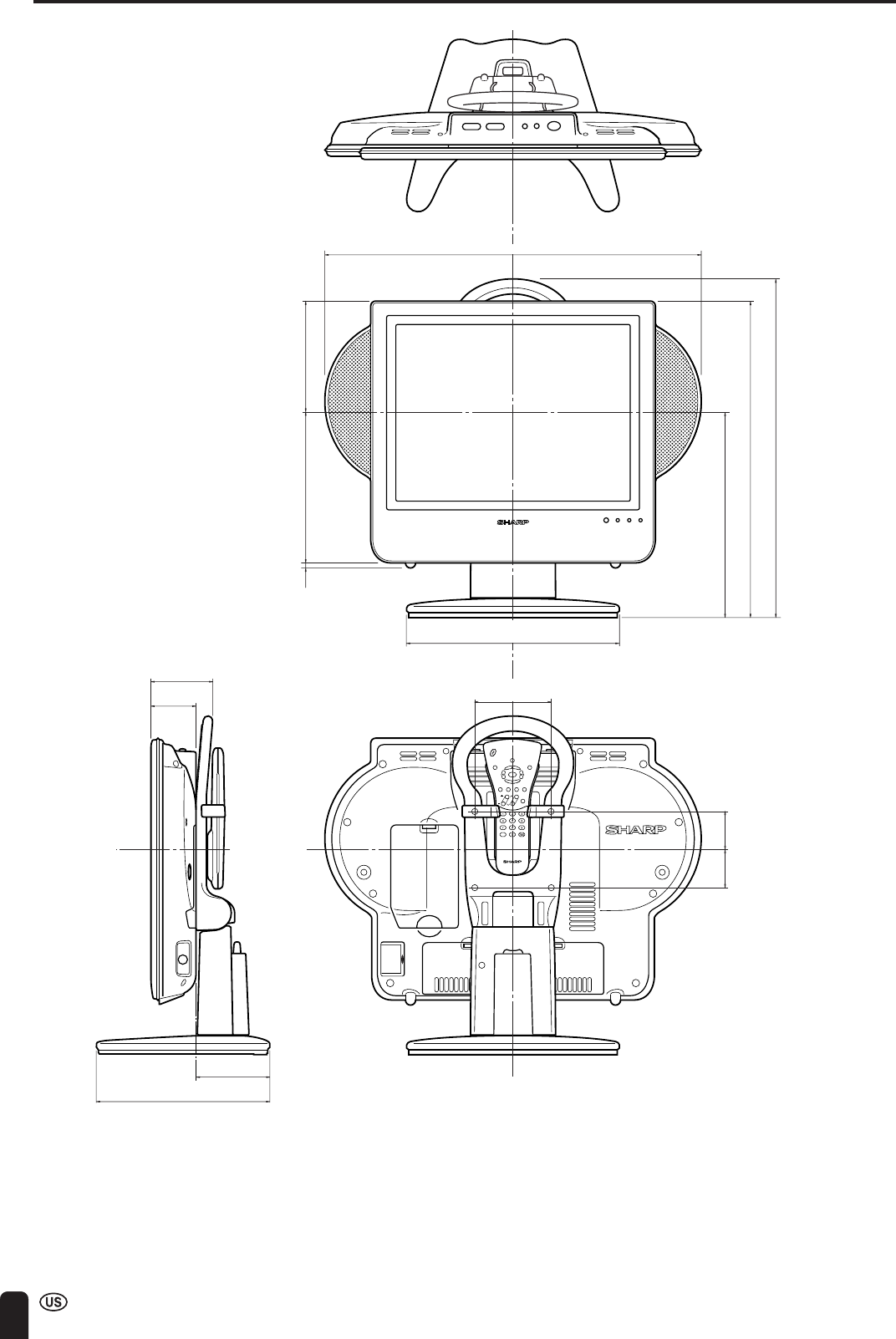
66
DIMENSIONAL DRAWINGS
Unit: inch (mm)
CHCH
ENTER
POWER
DISPLAY
SLEEP PIC. FLIP
MUTE
VOL
BRIGHT TV/VIDEO MENU
FLASH
BACK
MTS
8
63
/
64
(228)
2
21
/
64
(59)
3
13
/
64
(81)
3
53
/
64
(97)
11
1
/
32
(280)
3
15
/
16
(100)
19
29
/
64
(494)
10
5
/
8
(269.5)
1
31
/
32
(50)
1
31
/
32
(50)
16
11
/
32
(415)
17
17
/
32
(445)
7
/
32
(5.5)
7
53
/
64
(198.5) 5
47
/
64
(145.5)
ENGLISH
67
CALLING FOR SERVICE
For location of the nearest Sharp Authorized Service, or to obtain product literature, accessories, supplies, or customer
assistance, please call 1-800-BE-SHARP.
LIMITED WARRANTY
SHARP ELECTRONICS CORPORATION
Sharp Plaza, Mahwah, New Jersey 07430-2135
SHARP CORPORATION
CONSUMER LIMITED WARRANTY
SHARP ELECTRONICS CORPORATION warrants to the first consumer purchaser that this Sharp brand product (the “Product”), when
shipped in its original container, will be free from defective workmanship and materials, and agrees that it will, at its option, either repair the
defect or replace the defective Product or part thereof with a new or remanufactured equivalent at no charge to the purchaser for parts or
labor for the period(s) set forth below.
This warranty does not apply to any appearance items of the Product nor to the additional excluded item(s) set forth below nor to any Product
the exterior of which has been damaged or defaced, which has been subjected to improper voltage or other misuse, abnormal service or
handling, or which has been altered or modified in design or construction.
In order to enforce the rights under this limited warranty, the purchaser should follow the steps set forth below and provide proof of purchase
to the servicer.
The limited warranty described herein is in addition to whatever implied warranties may be granted to purchasers by law. ALL IMPLIED
WARRANTIES INCLUDING THE WARRANTIES OF MERCHANTABILITY AND FITNESS FOR USE ARE LIMITED TO THE PERIOD(S)
FROM THE DATE OF PURCHASE SET FORTH BELOW. Some states do not allow limitation on how long an implied warranty lasts, so the
above limitation may not apply to you.
Neither the sales personnel of the seller nor any other person is authorized to make any warranties other than those described herein, or to
extend the duration of any warranties beyond the time period described herein on behalf of Sharp.
The warranties described herein shall be the sole and exclusive warranties granted by Sharp and shall be the sole and exclusive remedy
available to the purchaser. Correction of defects, in the manner and for the period of time described herein, shall constitute complete
fulfillment of all liabilities and responsibilities of Sharp to the purchaser with respect to the Product, and shall constitute full satisfaction of all
claims, whether based on contract, negligence, strict liability or otherwise. In no event shall Sharp be liable, or in any way responsible, for
any damages or defects in the Product which were caused by repairs or attempted repairs performed by anyone other than an authorized
servicer. Nor shall Sharp be liable or in any way responsible for any incidental or consequential economic or property damage. Some states
do not allow the exclusion of incidental or consequential damages, so the above exclusion may not apply to you.
THIS WARRANTY GIVES YOU SPECIFIC LEGAL RIGHTS. YOU MAY ALSO HAVE OTHER RIGHTS WHICH VARY FORM STATE TO
STATE.
Model Specific Section
Your Product Model Number & Description: LC-15L1U LCD Color Television
(Be sure to have this information available when you need service for your Product.)
Warranty Period for this Product: One (1) year parts and labor from the date of purchase.
Additional Item(s) Excluded from
Warranty Coverage (if any): Non-rechargeable batteries.
Where to Obtain Service: From a Sharp Authorized Servicer located in the United States.
To find the location of the nearest Sharp Authorized Servicer, call Sharp toll free at 1-
800-BE-SHARP.
What to do to Obtain Service: Ship prepaid or carry in your Product to a Sharp Authorized Servicer. Be sure to have
Proof of Purchase available. If you ship the Product, be sure it is insured and packaged
securely.
TO OBTAIN PRODUCT INFORMATION, CALL 1-888-LCD-SHARP OR VISIT www.sharpusa.com
68
LIMITED WARRANTY
Consumer Electronics Products
Congratulations on your purchase!
Sharp Electronics of Canada Ltd. (hereinafter called “Sharp”) gives the following express warranty to the first consumer purchaser for this Sharp brand
product, when shipped in its original container and sold or distributed in Canada by Sharp or by an Authorized Sharp Dealer:
Sharp warrants that this product is free, under normal use and maintenance, from any defects in material and workmanship. If any such defects should be
found in this product within the applicable warranty period, Sharp shall, at its option, repair or replace the product as specified herein.
This warranty shall not apply to:
(a) Any defects caused or repairs required as a result of abusive operation, negligence, accident, improper installation or inappropriate use as outlined in
the owner’s manual.
(b) Any Sharp product tampered with, modified, adjusted or repaired by any party other than Sharp, Sharp’s Authorized Service Centers or Sharp’s
Authorized Servicing Dealers.
(c) Damage caused or repairs required as a result of the use with items not specified or approved by Sharp, including but not limited to head cleaning
tapes and chemical cleaning agents.
(d) Any replacement of accessories, glassware, consumable or peripheral items required through normal use of the product including but not limited to
earphones, remote controls, AC adapters, batteries, temperature probe, stylus, trays, filters, belts, ribbons, cables and paper.
(e) Any cosmetic damage to the surface or exterior that has been defaced or caused by normal wear and tear.
(f) Any damage caused by external or environmental conditions, including but not limited to transmission line/power line voltage or liquid spillage.
(g) Any product received without appropriate model, serial number and CSA/cUL markings.
(h) Any products used for rental or commercial purposes.
(i) Any installation, setup and/or programming charges.
Should this Sharp product fail to operate during the warranty period, warranty service may be obtained upon delivery of the Sharp product together with
proof of purchase and a copy of this LIMITED WARRANTY statement to an Authorized Sharp Service Center or an Authorized Sharp Servicing Dealer. In
home warranty service may be provided at Sharp’s discretion on any Sharp television with the screen size of 27” or larger and on any Sharp Over-the-
Range Microwave Oven.
This warranty constitutes the entire express warranty granted by Sharp and no other dealer, service center or their agent or employee is authorized to
extend, enlarge or transfer this warranty on behalf of Sharp. To the extent the law permits, Sharp disclaims any and all liability for direct or indirect
damages or losses or for any incidental, special or consequential damages or loss of profits resulting from a defect in material or workmanship relating to
the product, including damages for the loss of time or use of this Sharp product or the loss of information. The purchaser will be responsible for any
removal, reinstallation, transportation and insurance costs incurred. Correction of defects, in the manner and period of time described herein, constitute
complete fulfillment of all obligations and responsibilities of Sharp to the purchaser with respect to the product and shall constitute full satisfaction of all
claims, whether based on contract, negligence, strict liability or otherwise.
WARRANTY PERIODS: Parts & Labour (exceptions noted)
Audio Products 1 year
Camcorder 1 year
DVD Products 1 year
Projector 1 year (lamp 90 days)
LCD & Plasma Display TV 1 year
Microwave Oven 2 years (magnetron component-4 additional years)
Television Products 1 year (picture tube component-1 additional year)
VCR Product 1 year
Vacuum Cleaner 1 year
To obtain the name and address of the nearest Authorized Sharp Service Center or Dealer, please contact:
SHARP ELECTRONICS OF CANADA LTD. 335 Britannia Road East, Mississauga, Ontario L4Z 1W9
For more information on this Warranty, Sharp Extended Warranty
Offers, Sharp Canada Products, Accessory Sales, Dealer or Service
Locations, please call (905) 568-7140
Visit our Web site: www.sharp.ca
VALID IN CANADA ONLY