ShenZhen ART TECH R C Hobby ETB4SP 2.4GHz Radio Control system User Manual
ShenZhen ART-TECH R/C Hobby Co., Ltd 2.4GHz Radio Control system Users Manual
user manual

Remote control helicopter
Remote control helicopter
ANGEL
ANGEL
Operating manual
R

★SPARE PARTS LIST 15
★SAFETY INSTRUCTIONS FOR LI-POLY BATTERIES 06
★CHARGE MODE AND WARNING 05
★TIPS FOR SAFETY 03
★CAUTION 03
★SPECIFICATIONS 02
★INSTALLATION 11
★NORMAL FLIGHT 10
08
★
ADJUST THE SPEED OF THE ROTOR BLADES BY THE PCB BOARD
★MAIN ROTOR BLADE ADJUSTMENT 09
★THE POSSIBLE PROBLEMS AND SOLUTIONS
14
★PARTS LIST 07
★FUNCTIONS FOR CONTROL SET 08
★PARTS REPLACING 13
CATALOG
★GROUND EFFECT 09
www.art-tech.com
1
★中文说明部分 17-31
★SWASHPLATE ADJUSTMENT 09
★OPERATION MANUAL METHOD STARTING PROCEDURE 07
※This picture only for reference.
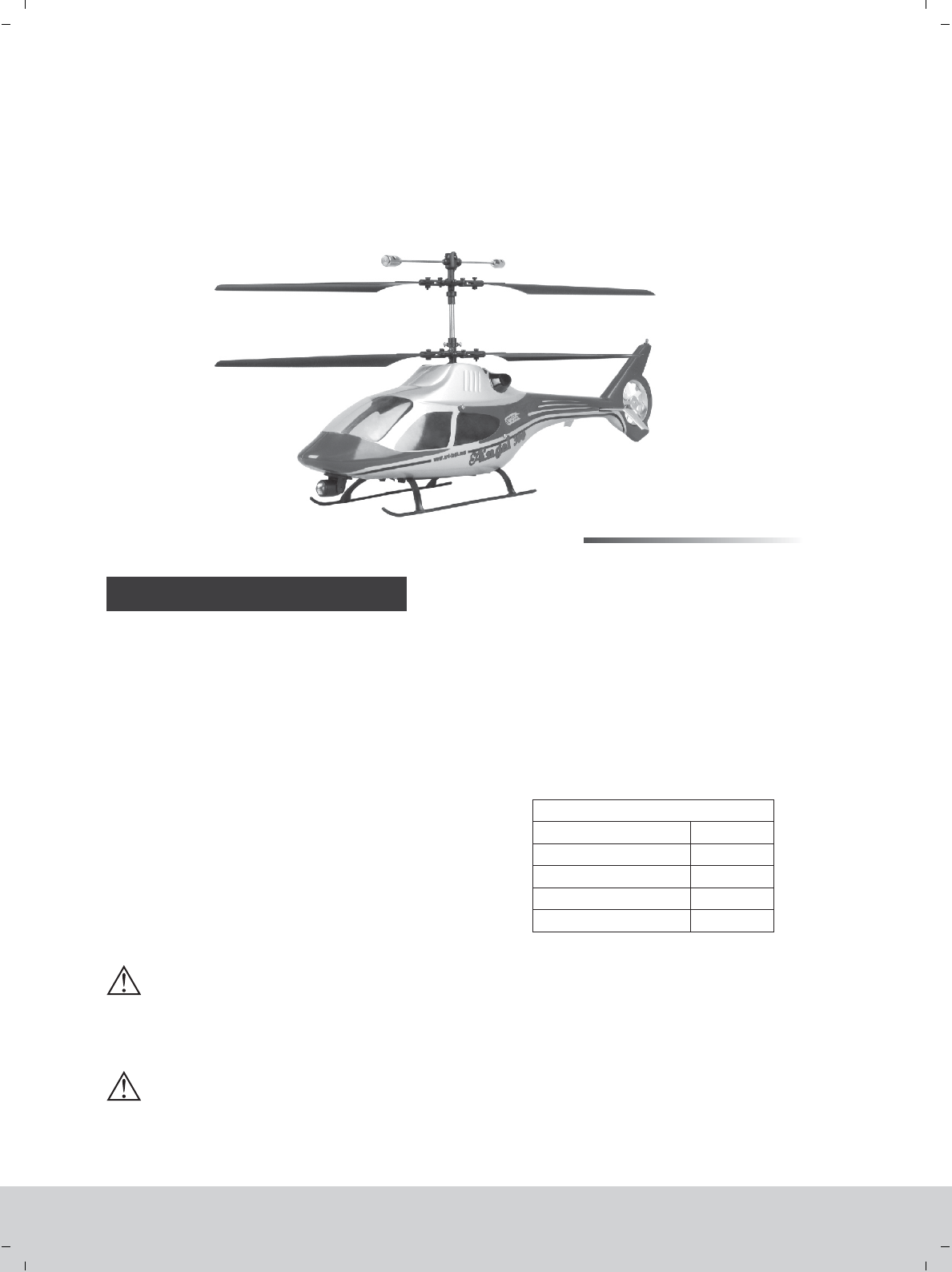
Thank you for purchasing our latest product--Angle 300 electric R/C helicopter. This helicopter is a
typical coaxial dual rotor helicopter and it’s our latest product. The frame is made of the high-strength
plastic and configured with scale flashers for night flight. This helicopter is super stable, easy to control and
it has a great maneuverability and accuracy. Moreover, this product has a vivid flying gesture and it is crash-
resistant. The flying time of each charge is more than 10min and it is an optimal model for the beginners. For
the safety operation of this helicopter, please make sure to read this manual carefully and follow all of the
safety notes strictly.
☆
Rotor diameter : 350mm
Length: 430mm
Height: 190mm
Weight: 260g
CONFIGURATION:
4 channel 2.4GHz radio system
180 class brushed motor
Li-Poly battery: 7.4V 1000mAh
2 pcs 8g servo
4 pcs blades
SPECIFICATIONS:
100%
★★☆☆☆
★★★
★
☆
★★☆ ☆
★☆☆☆☆
PRODUCT CHARACTER
Accomplishment
Difficulty of assembly
Difficulty of maintain
Difficulty of control
Anti-shatter
※Specifications may change without notice, please refer to the real one for configuration. 2009.06
Optimal helicopter for the beginner
Flying condition: indoor without wind
Coaxial counter-rotating structure
Easy control and stable flight
4 channel 2.4GHz radio system
Balance charger
Flying time: 10 mins
★
★
★
★
★
★
★
★
★
★
★
★
★
★
★
★
WARNING:
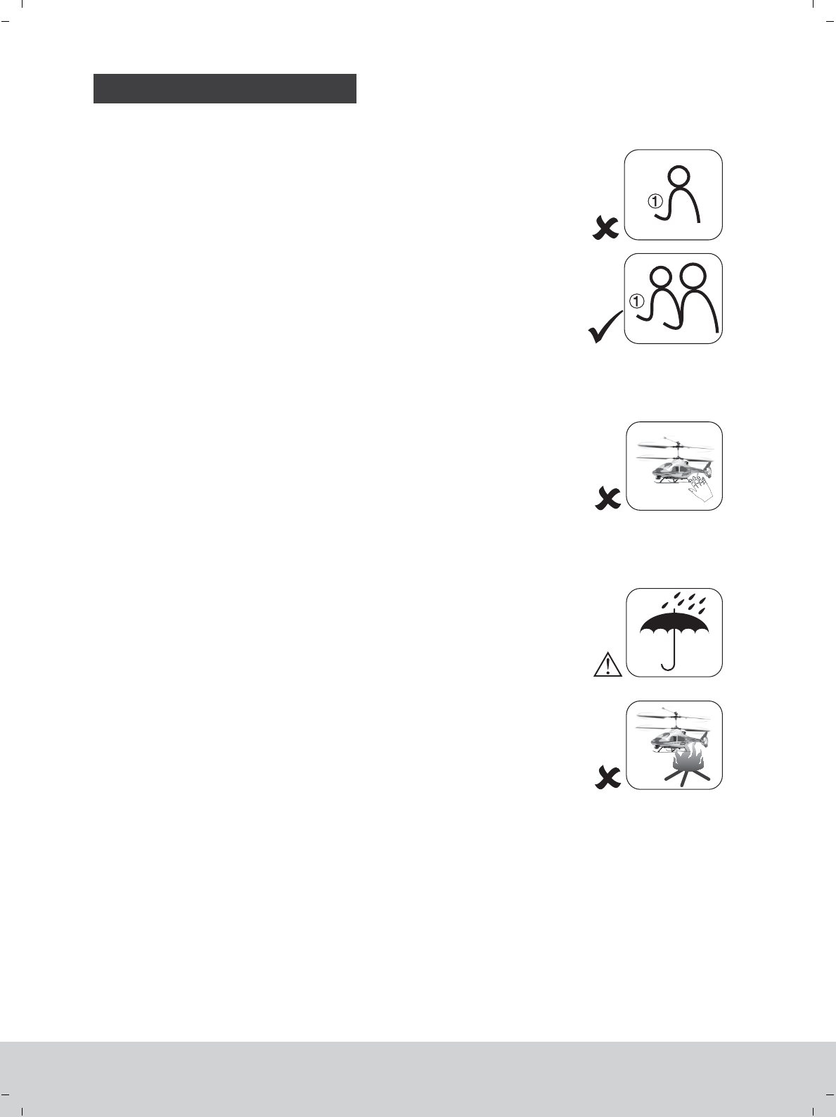
This product is for the ones that are above 14 years old.
Children should be supervised prior to starting or flying this helicopter.
Don’t touch the propellers after the product turned on.
★
www.art-tech.com
2
CAUTION
NOTE
TIPS FOR SAFETY
R/C modeling is a hobby with high technology and should not be considered as a toy. There is risk
involved during the operation of this product and the user should take all precautions seriously or serious
body injury may occur, it is only suitbale for the person above 14 years old.
Improper disassembly, improper adjustments or setup may lead to unsatisfactory or unsafe
operation. If you have any questions regarding the use, maintenance, or safe operation of this model,
please contact your local retailer.
As with any R/C product there are risks involved when flying this model. A beginner should seek the
help of a skilled R/C pilot to ensure that the model is airworthy and capable of safe operation. Any
damage, neglect, or unfamiliar use of this product can cause unexpected accidents or injury. Please
make sure the flying is safe and we are not responsible for any accident.
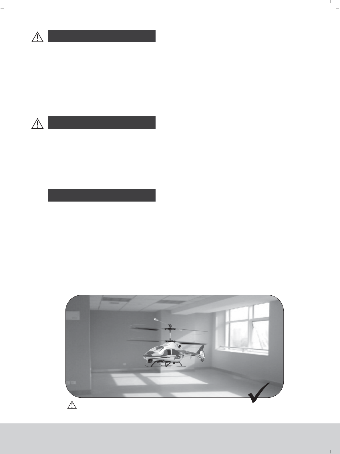
1. Locate an appropriate place to fly your helicopter:
R/C helicopters are capable of flying at high speeds, thus posing a certain degree of potential
danger to both the flyer and bystanders, so it is important to choose a right site for flying. First, the
space of flying site should be big enough (at least 4*4*4m). Second, the flying site should be open
enough, and clear of obstacles. Do not fly your helicopter during the strong counter-flow weather
to avoid the unnecessary damage.
This RC helicopter, angel 300, have the best performance in terms of control capability and
scalability without wind. it may not fly properly outside due to the fluency of airflow so that it is not
recommenced to fly outdoor.
www.art-tech.com
3
Without wind
TIPS FOR SAFETY
The help of an experienced pilot will ensure that you will have
a well trimmed, correctly functioning helicopter for the first flight.
It is strongly advised that you first practice on the simulator prior
to making a fli ght wit h your new heli copte r.
2. Obtain the assistance of an experienced pilot.
3. Always be away from the running parts
4. Keep your helicopter away from humidity.
5. Operate your helicopter gently
During the operation of your helicopter the rotor will be
spinning at a high rate of speed. Don’t touch any running parts and
please keep a proper distance with them. Be conscious of your
actions and be careful to keep your hands, face, eyes, and loose
clothing away from the blades and gears to avoid being hurt or any
damage to the model.
Your new Angle 300 helicopter is a hi-tech electronic device, so
try to keep the model away from the humidity condition which may
result in the operation errors or some other unrespectable faults to
the model.
Never subject your model to severe weather, such as raining,
thunder.
The helicopter will give a prompt response to the controlling
action,so try to operate the helicopter gently. Try to avoid the
excessive operation as this may lead to the helicopter to be out of
control.
Novice
Novice Expert
www.art-tech.com
4
CHARGE MODE AND WARNING
Specifications:
Input voltage: DC 10V~15V
Output voltage: DC 7.4V&11.1V (To 2 or 3 cell Li-poly battery)
Charge current: 0.3A~1.0A (Can be continuously adjusted)
Indicator state:
Green: Charge complete or no battery
Red: Charging
Flash: Drip current charging
Separated battery detection: The voltage of any battery reaches
4.2V, the charge of it will cease automatically.
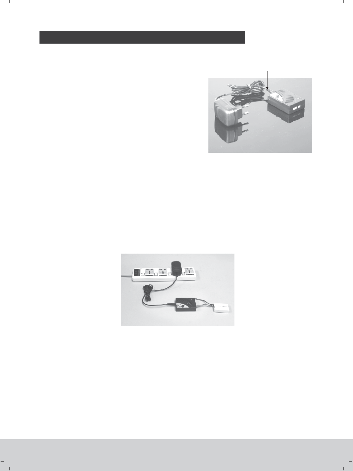
Li-Po battery(balance changer)
ATI-0910 Li-poly battery balance charger using instruction 12V DC Power supplier
Using method:
1. Connect the cigarette with charger per above image
2. Then plug cigarette into its socket in car (Adapter should be connected if charge at home: connect the adapter
to home power socket, then plug the adapter’s DC end to charger). The LED will turn green indicating it is ready
for charging.
3. Connect the battery to the charger per its interface mark. The LED becomes red, which means the battery is
on the way.
4. Adjust the charge current. In order to prolong battery’s life-span, we recommend charging them under low
current if you have enough time.
5. When the LED flashing, the charger will enter the stage of drip current charging. The LED turns green when
fully charged, and the battery will be used at any time.
Notice
1. Do not insert any conductive into the cooling hole when power is on, or damage will be caused to the charger.
2. While charging is in process, please do not place it near flammable materials.
3. It is not allowed to charge two-cell and three-cell Li poly battery at the same time.
4. Expect Li poly battery, this charger is not allowed for other kinds of battery.
5. While charging, please keep it out of the reach of Children.
6. When this charger is in use, please do not go away and leave it unwatched, if any abnormality occurs (such as the
power indicator is off, the temperature of the battery rise rapidly, etc.) stop charging immediately.
7. Please do not use power with output voltage higher than 15V.
8. Please do not disassemble the charger or its accessories.
9. When the battery is not cool down, please do not urge to charge it.
www.art-tech.com
5
CAUTION
SAFETY INSTRUCTIONS FOR LI-POLY BATTERIES
01.Do not disassemble or reconstruct the battery.
02.Do not short-circuit the battery.
03.Do not use or leave the battery nearby the fire, stove or heated place.
04.Do not immerse the battery in water or sea water, do not get it wet.
05.Do not charge the battery nearby the fire or under the blazing sunlight.
06.Do not drive a nail into the battery, strike it by hammer or tread on it.
07.Do not impact or throw the battery.
08.Do not use the battery with conspicuous damage or deformation.
09.Do not make the direct soldering on the battery.
10.Do not reverse charge or over discharge the battery.
11.Do not reverse charge or reverse connect.
12.Do not connect the battery to the ordinary charger socket or car cigarette jack.
13.Do not use the battery for unspecified equipment.
15.Do not mix the Li-Poly battery with other un-chargeable batter y .
16.Do not continue charging the battery over the time.prescribed
17.Do not put the battery into the microwave oven or high-pressure container.
18.Do not use the abnormal battery.
19.Do not use or keep the battery under the sunlight.
20.Do not use the battery nearby the place where generates static electricity (over 64V).
21.Do not charge the battery when the environmental temperature is under 0℃ or over 45℃.
22.If you find the battery leaking, smelling or abnormal, stop using it .
23.Keep the battery away from the children.
24.Use the specified charger and observe charging requirement (under 1A).
25.When using by minors, parents should show them the correct way to charge.
14.Do not touch the leaking battery directly, please wash your skin or clothes with water
if they are bedewed by liquid leaking from the battery.
1. Use the original charger. Never charge the battery at more than 1 amp.
2. Never discharge the battery at more than 5C. Do not discharge too long as this will damage the battery.
3. For full flight time to be achieved please cycle the cells through three flights.
4. Never charge the battery on a carpet floor, this can cause a fire!
www.art-tech.com
6
PARTS LIST
Fuselage
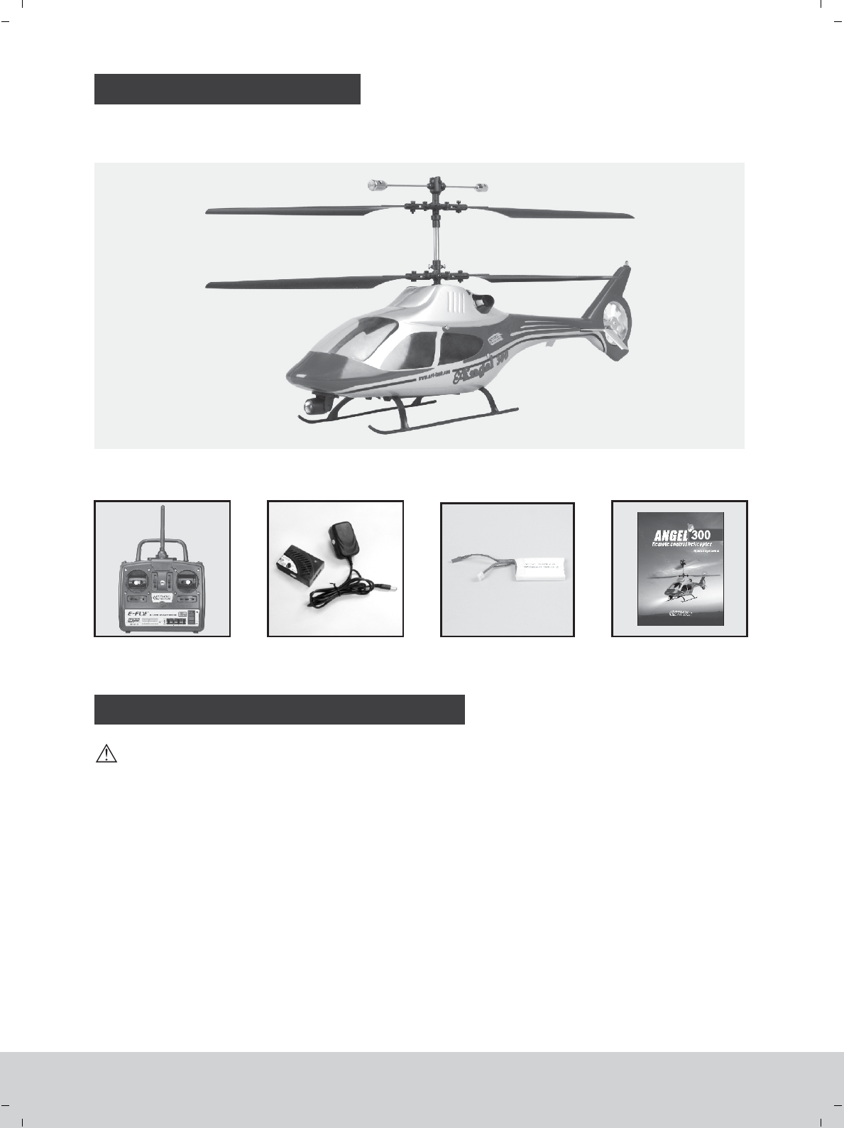
The helicopter includes the following parts, please check to make sure that all of the parts are included in
your kit. If there is anything missing please contact your local dealer.
OPERATION MANUAL METHOD
1. Put the helicopter on the flat ground and put the transmitter one meter away from the helicopter.
2. You can find that the indicator light of controlling board will flash by the transparent window in the right side of
fuselage after connecting the power.
3. Turn on the switch of transmitter, the indicator light of transmiter start to flash in red light and green light in turn.
4. If the indicator light of the controlling board will turn to solid red and the indicator light of the transmitters turn
to solide green after 7 seconds and you can hear Crunch of the servo’s movement( the servo will move to the
center), it means the helicopter is ready for flying. After self-inspection, you can start to fly. Otherwise, cut down
the power for the helicopter and transmitter, then repeat the step from 1 to 4.
Caution!
1. Do not move or shack helicopter during the process of starting up, which may lead to abnormal flight.
2. Before starting the operation, it should be confirmed that there are no RC aircraft doing the same operation
inside 30 meters, otherwise, the helicopter may lose control.
Balance Charger Li-po battery Operating manual
Transmitter
Please follow the following process before starting, Otherwise, it may lead to the helicopter not to work.
www.art-tech.com
7
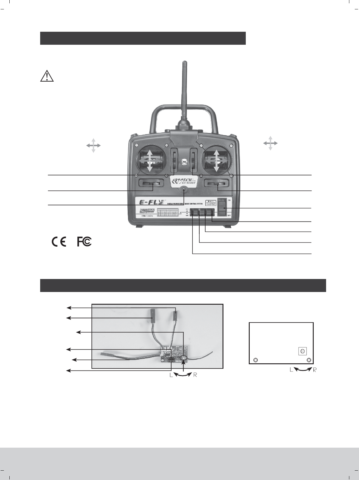
FUNCTIONS FOR CONTROL SET
Mode 2(left hand throttle)
Throttle Max Elevator down
Rudder
left
Aileron
left
Rudder
right
Aileron
right
Elevator upThrottle Min
Ch2 ( ) Trim adjustmentelevator
Power switch
Reverse switch on CH4(rudder)
Reverse switch on CH3(throttle)
Reverse switch on CH2(elevator)
Reverse switch on CH1(aileron)
Ch1 (aileron) Trim adjustment
Ch3 ( ) Trim adjustmentthrottle
Ch4 (rudder) Trim adjustment
ADJUST THE SPEED OF THE ROTOR BLADES BY THE PCB BOARD
Power wire
* Motor 1
* Sevor 2
* Motor 2
* Sevor 1
1.Funtion of knob: adjust the gesture of the helicopter by adjusting the speed of upper and lower rotor blades.
(1) If you turn the knob clockwise, the speed of the downward rotor blade will increase and helicopter will turn
right.
(2) If you turn the knob widdershins, the speed of the upper rotor blade will increase and helicopter will turn left.
2.PCB is well adjusted before shipment, so the end-customer need not adjust it.
www.art-tech.com
8
LED Indicator
* Please refer to the page 13 for the position of servos and motor
Rotor blade speed
difference adjust
knob
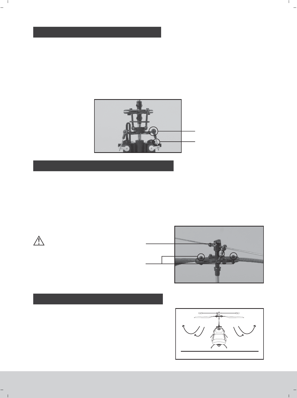
MAIN ROTOR BLADE ADJUSTMENT
1. Main rotor blade inspection.
(1) Inspect whether the fixed screws of the main rotor blades are too tight or loose. Extreme tightness or loosing
of the blades will result in unstable flight.
(2) Inspect whether the blade tracking phenomenon will happen. Blade tracking problem will lead to unstable
flight.
2. Adjustment for the main rotor blade
(1) Keep the fixed screw of the main rotor blades not too tight or too loose.
(2) Lengthen or shorten the ball linkage rod if the blade tracking
problem is existed.
GROUND EFFECT
displaced caused during the
transportation and flying. Please
adjust the trim properly before you
fly the model. The position of
transmiter trim may changed slightly
due to transportation. Please check
the state of trim and adjust knot
according the flying.
The trims of the transmitter may be
Airplane will be influenced by the airflow when airplane
is flying 30 centimeters above ground, which is called
‘ground effect’. This effect can increase the lift and also
make the helicopter difficult to control in the situation. It will
be difficult for the helicopter to take off and land in this
situation. The best way to reduce the ‘ground effect’ is to
increase the flight altitude.
SWASHPLATE ADJUSTMENT
1. Swashplate check. Pull down the throttle joystick and throttle trim to the lowest position, and push the
elevator trim and aileron inching switch to the neutral position, and check whether the swashplate is in a
horizontal level.
2. Swashplate adjustment:
If the swashplate is not in a horizontal level, adjust via the following steps:
First, loosen the swashplate pull rod (Disconnect the ball buckle with the swashplate). Second, turn the ball
buckle clockwise or anticlockwise to adjust the length of the pull rod so as to make the swashplate reach level.
Third, connect the ball buckle.
Ball head buckle
Swashplate bearing
ball connector rod
fixed screw for
main blades
www.art-tech.com
9
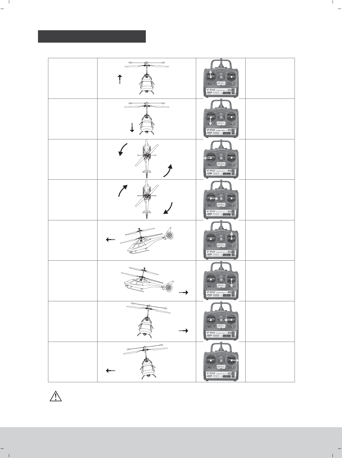
NORMAL FLIGHT
Chart for R/C mode 2(left hand throttle)
Ascending
Descending
Head turning left
Head turning right
Head forward
Head backward
Left stick
pushing up
Left stick
pulling down
Left
moving left
stick
Left
moving right
stick
Right stick
pushing up
Right
pushing down
stick
Right
moving left
stick
Right
moving right
stick
Helicopter
moving left
Helicopter
moving right
www.art-tech.com
10
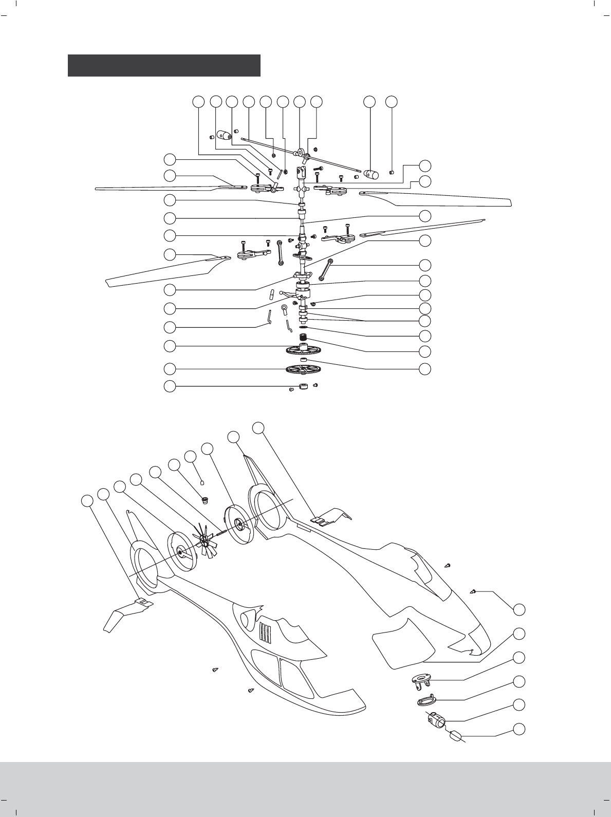
INSTALLATION
33
34
35
36
37
38
39
40
41
42
43
44
45
46
47
48
1
3
4
5
6
7
8
9
10
11
12
13 14 15 16 17 18 19 20 21 22
23
24
25
2
26
10
27
28
29
30
31
32
65
www.art-tech.com
11
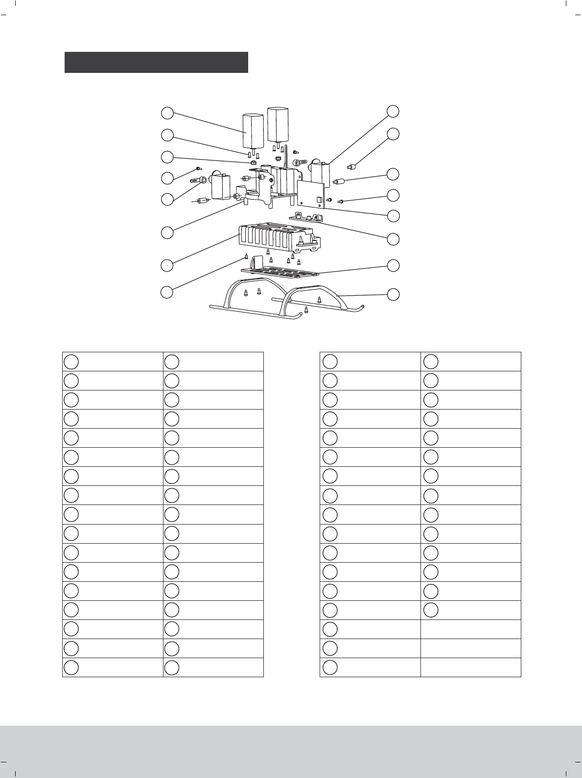
INSTALLATION
18
19
20
21
22
1
2
3
4
5
52
53
54
55
56
57
58
59
60
61
62
63
64
35
36
37
38
39
40
41
42
43
44
45
46
48
49
50
47
49
50
51
52
53
54
55
56 57
58
59
60
61
62
63
64
6
7
9
10
11
12
13
14
15
16
17
23
24
25
26
27
28
29
30
31
32
33
34
8
The fixed sleeve
for main shaft Servo arm
Screw
Copper gear
Motor
Servo
Link bar 1
Controlling board
Controlling board seat
Battery cover
Undercarriage
51
Nut
Balance bar sleeve
Balance bar ball buckle
Stabilizer
Rotor head
Inner main shaft
Outer main shaft
Linkage rod
Bearing
Main shaft fixed sleeve 2
Main gearing copper sheet
Copper sleeve
Left stabilizer
Left body
Left tail blade cover
LED light
LED light seat
Tail blade shaft
Tail blade
Right tail blade cover
Right body
Right stabilizer
Searchlight
Searchlight cover
Searchlight sleeve holder
Searchlight seat
Canopy window
Screw
Battery box
Frame
65 Rotor holder
Upper main gear
Lower main gear
Servo arm steel wire
Inner inclined tray
Outer inclined tray
Right rotor blade
Rotor head sheath
Connecting sleeve
Bearing
Left rotor blade
Screw
Main rotor ball buckle
Screw
Pull rod
Balance bar
Copper sleeve for
balance bar
Screw
Screw
Bearing
Screw
Screw
Link bar 2
Screw
www.art-tech.com
12
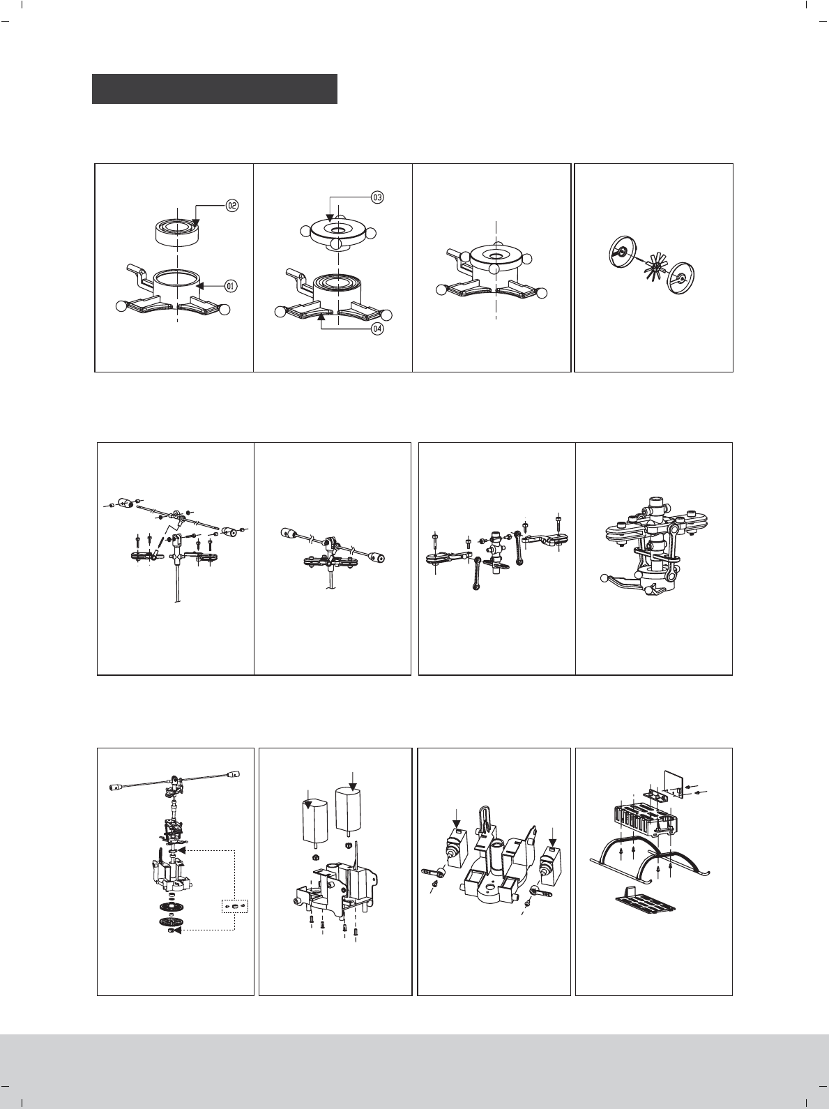
PARTS REPLACING
1. Put ② into ①.
Sketch map of upper rotor
wing grip.
Sketch map of lower rotor
wing grip.
Upper rotor wing grip installation Lower rotor wing grip installation
Main rotor shaft and core
shaft installation Motor installation Servo installation Undercarriage and Battery
box installation
Swashplate assembly Tail wing assembly
Servo 2
2. ③ ④Put into .Press step 1 into step 2 to
form a new compenent.
Please follow the sketch map to
assembly the tail wing
Please follow the sketch map to
install the upper rotor wing grip.
Please follow the sketch map to
install the lower rotor wing grip
Please follow the sketch map to
install the main rotor shaft
Please follow the sketch map to
assemble the motor set.
Please follow the sketch map to
assemble the servo set.
Please follow the sketch map to
assemble undercarriage, battery
box and controlling board
www.art-tech.com
13
Servo 1
Motor 2
Motor 1
1.Slight spinning could be corrected by
adjusting the trim of CH4 (rudder)
2. If the problem is serious, first neutral
the trim slider and then adjust the knob
of the PCB board. (see page 8)
The two methods should be used
together to solve the problem.
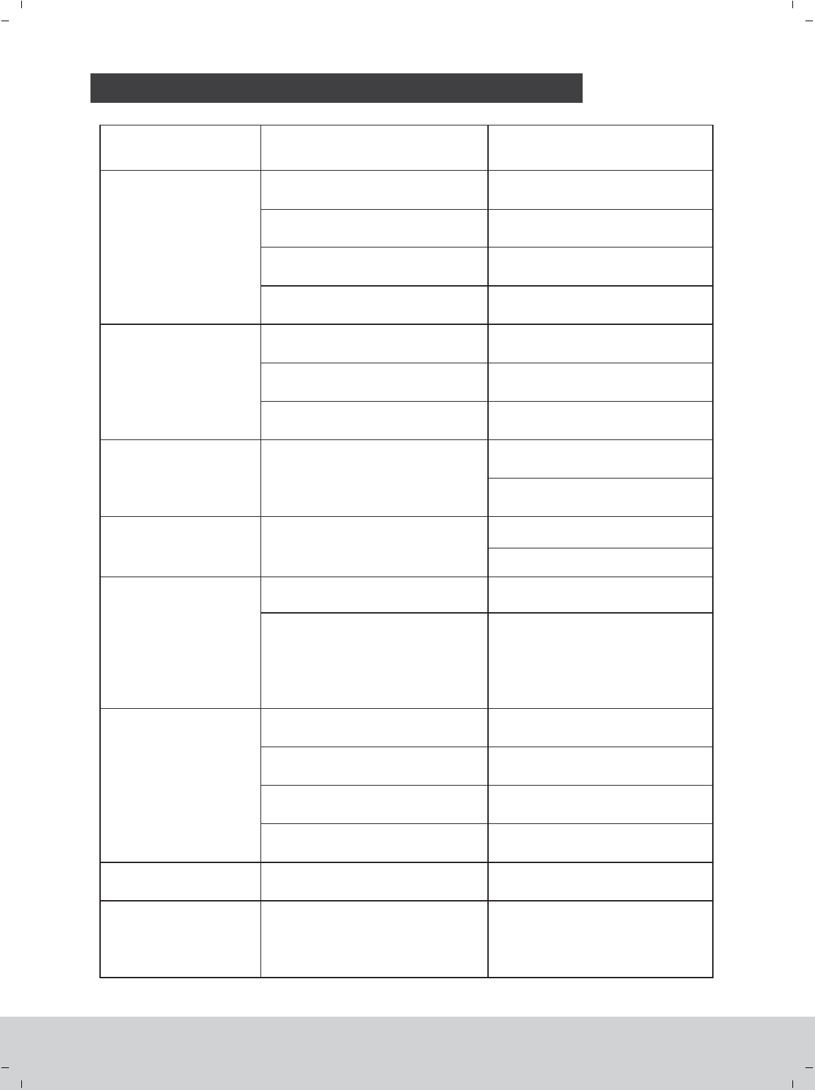
Problem Cause Reparation
The model does
not move
Check the battery voltage of transmitter
and receiver
Check the wire connection inside the model
Improper starting operation
Thruthle protecting function swiched on
Use completely charged batteries
Contact the local dealer
Restart the model (See page 7)
Minimize the right joystick of thrutle
(See page 8)
The model is out of
control or the flight
is unstable
The model flies beyond the control distance
The stabilizer of the balance bar is off
The ball connector buckle is off
Control the flying distance
Install the stabilizer properly (See page 13)
Connect the buckle again (See page 9)
The model moves only
forwards/ backward The swash plate is not level
Correct the trim on the transmitter (CH 2)
(See page 8)
Balance the swash plate(See page 9)
The model slides
left/right always
Correct the trim on the transmitter (CH 1)
(See page 8)
The swash plate is not level
The model is spinning
all the time The upper and lower blades rotate
with different speed
One or more blades are broken or deformed Change the rotor blades *
The model vibrates
severely with much noise
There is too much friction between the gears Apply some lubricating oil
Rotor blades are twisted
Check the rotor blades to see if there is any
inconsistent phenomena during the rotation
Check the connection of the body and the
frame
Adjust the pull rod properly and adjust
the blades to provent tracking blade
(see page 9)
Make the connection of the body and
frame firm enough
Change the batteryThe battery of transmitter is not sufficient
Short control distance
The model moves forwards/
backward and sidewise, but
does not hover
Check whether the helicopter is exposed
to a draught, e.g. by an opened window or
an air conditioner. Hover flight is not
possible when there is a draught
Close the window / door, switch off the
air conditioner or select a more suitable
place
Change the rotor blades *
* Note: If one rotor blade is changed, please change the other blade simultaneous also to make sure the two
blades are with the same weight.
THE POSSIBLE PROBLEMS AND SOLUTIONS
www.art-tech.com
14
Balance the swash plate(See page 9)
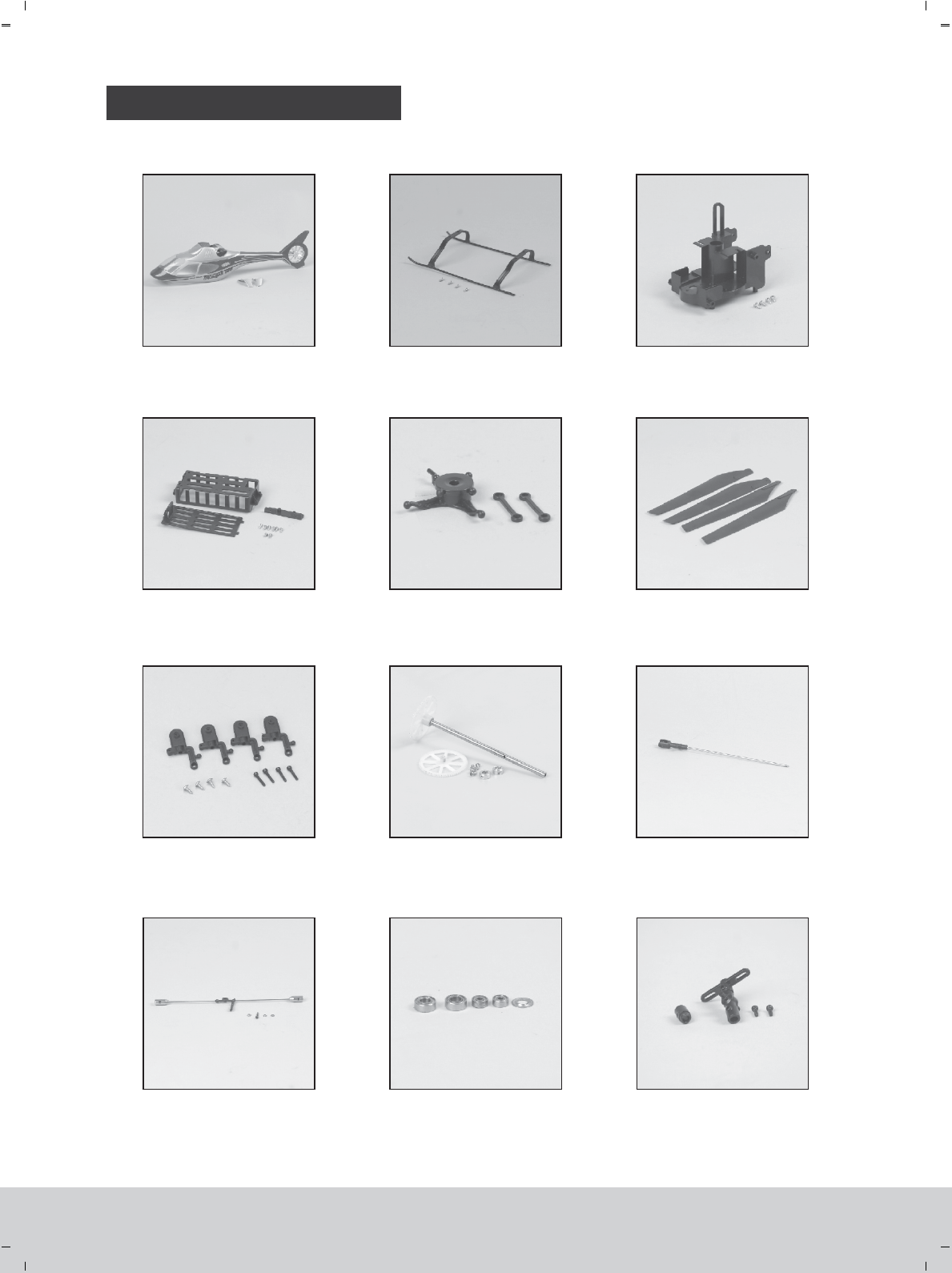
SPARE PARTS LIST
No:4R011
Body
No:4R021
Undercarriage
No:4R031
Frame
No:4R041
Battery box set
No:4R051
Swash plate No:4R061
Main blades
No:4D101
Main rotor wing grip
No:4R071
Main gear set No:4R081
Core shaft
No:4R141
Stabilizer
No:4R091
Bearing set
No:4R101
Rotor head set
www.art-tech.com
15

SPARE PARTS LIST
No:4R111
Arm set
No:3R021
Controlling board (PCB)
No:4R131
Motor set
No:35051
Servo
No:4D051
Li-poly battery
No:4J011
Upgraded carbon blades
No:4R121
Searchlight
www.art-tech.com
16
FCC Statement
This equipment has been tested and found to comply with the limits for a Class B digital device,
pursuant to part 15 of the FCC rules. These limits are designed to provide reasonable protection
against harmful interference in a residential installation. This equipment generates, uses and can
radiate radio frequency energy and, if not installed and used in accordance with the instructions,
may cause harmful interference to radio communications. However, there is no guarantee that
interference will not occur in a particular installation. If this equipment does cause harmful
interference
to radio or television reception, which can be determined by turning the equipment off and on, the
user is encouraged to try to correct the interference by one or more of the following measures:
-Reorient or relocate the receiving antenna.
-Increase the separation between the equipment and receiver.
-Connect the equipment into an outlet on a circuit different from that to which the receiver is
connected.
-Consult the dealer or an experienced radio/TV technician for help.
To assure continued compliance, any changes or modifications not expressly approved by the party
responsible for compliance could void the user’s authority to operate this equipment. (Example- use
only shielded interface cables when connecting to computer or peripheral devices).
FCC Radiation Exposure Statement
This equipment complies with FCC radiation exposure limits set forth for an uncontrolled
environment and it also complies with Part 15 of FCC RF Rules. Operation is subject to the
following two conditions:
1) This device may not cause interference and
2) This device must accept any interference, including interference that may cause undesired
operation of the device.
Caution!
The manufacturer is not responsible for any radio or TV interference caused by unauthorized
modifications to this equipment. Such modifications could void the user authority to operate the
equipment.
Declaration of Conformity
Hereby, ShenZhen ART-TECH R/C Hobby Co., Ltd. declares that this device is in compliance
with the essential requirements and other relevant provisions of Directive 1999/5/EC.
We also declared that the medium access protocol has been implemented.