ShenZhen LanGi Technology 6001000RT Wireless Video Transmission User Manual UPDATED FCC 11 2

ShenZhen LanGi Technology Co. LTD. Wireless Video Transmission UPDATED FCC 11 2
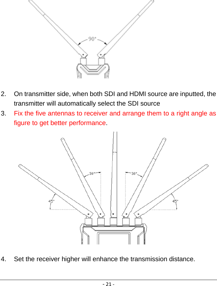
User Manual

‐1‐The Manual of the Product  Table of Contents ImportantInformation......................................................................................‐1‐SpecialNotice:...................................................................................................‐2‐Introduction.......................................................................................................‐3‐Thedetailsoftheproduct.........................................................................‐3‐Theparametersoftheproduct.................................................................‐7‐Thefeaturesoftheproduct.......................................................................‐8‐Accessories List..............................................................................................‐9‐MachineInformation.......................................................................................‐11‐Transmitter(TX)........................................................................................‐11‐Receiver(RX).............................................................................................‐14‐Useyourequipment........................................................................................‐17‐Aboveall,preparethetransmitter..........................................................‐17‐Then,preparethereceiver......................................................................‐18‐Attheend,setthechanneltothesame.................................................‐18‐TXchannelschanging..............................................................................‐18‐RXchannelschanging..............................................................................‐19‐Tipsforabetterusing......................................................................................‐20‐Trouble‐shooting.............................................................................................‐22‐FCCStatement.................................................................................................‐24‐FCCRadiationExposureStatement.................................................................‐25‐Cautions!.........................................................................................................‐25‐Important Information Please take the time to read this user manual before use the Product, it contains all notes and important information regarding your wireless HD video transmission system. Our limited warranty applies when the products is handled properly for intended use, in accordance with its operating instruction.   However the warranty may be void in the following cases:
‐2‐  Repairs or product modification have been executed by unauthorized service personnel.   The damages are caused by accidents including but not limited to, lighting, exposed to rain or water and moisture.   The model number on the product has been modified or the warranty tag has been removed   Warnings  This product uses for indoor environment,should not be exposed to dripping or splashing     Place receiver/transmitter on a flat, hard and stable surface  Ventilation: Do not block the ventilation slots on the receiver/transmitter or place any heavy object on the top cover   Put the receiver/transmitter in a property ventilated area, away from direct sunlight or any source of heat.   Water Exposure: To reduce the risk of fire or electric shock, do not expose the receiver/transmitter to rain or moisture.   Our company has the right to modify this document without any notice.    Special Notice:   Use of this product in the following locations may result in abnormal video and audio output(noise, blocked image… etc.) 1.  Product installed in the walls made of concrete. 2.  Product is situated near the refrigerator or metal fitment. 3.  A cluttered room where the wireless signals may be blocked.   This product has been tested and manufactured to comply with each country’s safety rules. However, there is no guarantee that interference will not occur in some installation scenario. If the interference happens, increase the distance between the transmitter
‐3‐and receiver.  Introduction This equipment is designed to replace the current widely used cable in the live broadcasting and production environment, it can be used in film production, live broadcasting as well as many application which requires good quality wireless video connection.The details of the product The equipment include the series models: SH700M/SH1000M, 600M/1000M and 600M-ENG/1000M-ENG.  It is consist of one transmitter (TX) and one receiver (RX).
‐4‐ 1. 600M and 1000M   TXRX
‐5‐2. SH700M and SH1000M  TXRX
‐6‐4. 600M‐ENGand1000M‐ENG   RXTX
‐7‐The parameters of the product   ITEM  SPECIFICATION Frequency 5190,5230,5755 and 5795MHz Bandwidth 40MHz Video Formats Supported 1080p 23.98/24/25/30/50/60 1080psf 23.98/24/25 1080i 50/59.94/60 720p 50/59.94/60 576p 576i 480p 480i Audio Formats Supported  PCM, DTS-HD, Dolby TrueHD TransmissionRange  1500ft(Line of sight)                                      Transmitter  Antenna    External Antenna × 2pcs Transmission Power          24dBm Functional Interface HDMI Input; SDI Input; SDI Loop Output; Mini USB; LEMO Power IN; Antenna RPSMA Socket; Power ON/OFF              Mounting Structure  1/4” Hot-shoe connection OLED Display  Wireless Channel Info; video status; Battery info. Working Voltage  9-18V    by DC input, F970 battery Power Consumption  7-9W Net Weight(with antenna)  400g Dimensions 142.5×76×24.3mm Temperature  -10-50℃(Operating); -40-80℃(Storage)                                       Receiver                Antenna    External Antenna × 5pcs Receiving Sensitivity  -70dBm
‐8‐Functional Interface SDI Dual Output; HDMI Output; Mini USB;   LEMO Power IN; Antenna RPSMA Socket;   Power ON/OFF Locating Structure  1/4” Hot-shoe connection OLED Display  Wireless Channel Info; SDI/HDMI Input Info; Signal Status; Power Info Working Voltage  9-18V by DC input, SONY V-mount battery Power Consumption  7-8W Net Weight(with antenna)  800g  Dimensions  169.5×122×25.2mm       Temperature  -10-50℃(Operating); -40-80℃(Storage) *Since the product’s improving process, all the performance, design and specifications of our products are subject to minor change without prior notice.  The features of the product   Uncompressed 3G/HD/SD-SDI and HDMI, up to 1080p 50/60  Less than 1 frame latency There is no discernible video delay and you can use it as real time on-location monitoring.  Operating range: 1500ft (line of sight), the transmission distance may be different, depend on surroundings, radio wave conditions, buildings block, etc.  Operating band: 5GHz ISM band    Multicast support Support one transmitter to multi receivers. User can set channel to pair both the transmitter and receivers.  Built-in fan TX side built-in high efficiency ventilation fan with very small noise.  OLED shown in work status  All-Metal Shell
‐9‐Both transmitter and receiver adapt metal shell which is durable and solid.  Simple connection The wireless system is plug-and-play designed, without any software configuration.                          Accessories List Accessories of all models are subject to the following packing list.
‐10‐          Antenna x 8 Power cable x 2 2-pin Lemo to BTap      SDI Cable x 2                               7” Articulating Arm x 1      Hot-shoe Stand x 1
‐11‐Machine Information Transmitter(TX)
‐12‐
‐13‐ STRUCTURE 1  OLED Display Displays information of channel, Video status and battery capacity. 2  UP Button Channel +   3  DOWN Button Channel -   4  MENU Button Unlock the channel and Confirm the Selection 5  Power ON/OFF Turn ON or OFF the transmitter 6  SDI IN Connect to SDI Video Source 7  SDI OUT(Loop Through) Connect to the your monitor or other 8  HDMI IN Connect to HDMI Video source 9  DC IN(Lemo)   Support 9-18V 10  Antenna Connector x2 Fix antennas 11  Battery Clip Battery compartment, for F550/F970 battery
‐14‐Receiver(RX)
‐15‐
‐16‐STRUCTURE 1  Antenna Connector x5 RPSMA connectors for antennas 2 OLED Display Displays information of channel, signal strength and battery capacity. 3 MENU Button Unlock and Confirm the Selection 4 LEFT Button Channel - 5 RIGHT/DOWN Button Channel + 6 V+/UP Button Volume +, not use on this version 7 V-/DOWN Button Volume -, not use on this version 8 BAT-OUT(B-TAP socket) Provide DC power supply from the battery for external equipment 9 HDMI OUT Connect to your HDMI monitor or other 10 SDI OUTx2 Connect to your SDI monitor or other 11  DC IN(Lemo) *Support 9-18V Support 9-18V
‐17‐12 Battery Clip Support V-Mount battery 13 Power ON/OFF Power on or OFF the receiver Use your equipment Above all, prepare the transmitter 1.  Connect your SDI or HDMI video source to the “SDI IN”/”HDMI IN” port of transmitter (when both SDI and HDMI video are inputted to the
‐18‐transmitter, it will auto select the SDI video for transmission). 2.  If need, you can connect the SDI out(loop through) to other equipment as well 3.  Fix the antenna 4.  Connect to a “B-TAP” battery by through power cable or insert F970 battery to the transmitter 5.  Power on the transmitter 6.  Set the Channel  Then, prepare the receiver 1.  Connect “SDI OUT”/”HDMI OUT” port of receiver to monitor or other device. 2.  Fix the antenna 3.  Connect to a “B-TAP” battery by through power cable or insert V-type battery to the receiver 4.  Power on the Receiver 5.  Set the Channel (must set both transmitter and receiver to the same channel) 6.  After 5-10s, the transmission video will be shown on monitor  At the end, set the channel to the same Both Transmitter and Receiver were set to same channel in Manufactory. In case, you want to change to a new channel, please follow the below: Remark: Both transmitter and receiver must be set to same one TX channels changing Step1: Power on the transmitter
‐19‐Step2: Press “MENU” button until shown in the unlock icon  on OLED.   Step3: Press “Up” or “DOWN” button to choose channel, then press “MENU” to confirm. Step4: Transmitter channel setting accomplished.     RX channels changing Step1: Power on the Receiver Step2: Press “MENU” button until display unlock icon .  Step3: Click Left or Right button to choose channel, then click “MENU” to confirm. Step4: Receiver channel setting accomplished.
‐20‐     Tips for a better using 1.  Fix the two antennas to the transmitter and arrange them to be a right angle as below figure to get better performance.
‐21‐  2.  On transmitter side, when both SDI and HDMI source are inputted, the transmitter will automatically select the SDI source 3.  Fix the five antennas to receiver and arrange them to a right angle as figure to get better performance.   4.  Set the receiver higher will enhance the transmission distance.
‐22‐ Trouble-shooting If the receiver failed to output the video correctly, the possible causes are as below, please find the solution from following chart: TROUBLES&POSSIBLEREASONS:SOLUTON:OSD Information on TV Displaying “Waiting for connection…” for a long time Transmitter is not powered up.  Power on the transmitter. Transmitter or receiver is not placed correctly. Place the TX or RX correctly. The transmitter and receiver are too far away. Move the receiver closer to the transmitter. Several solid wall partition on TX and RX. Reduce the number of solid walls between TX and RX. There are so many obstacles between TX and RX. Move the receiver closer to the transmitter. Other transmitter is working on the same or adjacent channel. Turn off other transmitter, or change channel. No Video Signal received Transmitter and video source are not connected. Connect the transmitter to video source by SDI/HDMI cable. The video source is turned OFF  Power ON the video source. Bad contact of cable of transmitter.  Remove and then re-plug the transmitter   Abnormal working of transmitter  Reboot the transmitter Problem with cable between TX and video source Change the SDI/HDMI cable Player NOT support the output resolution format. Switch the output video resolution to other modes.
‐23‐The TV/Monitor NOT support HDCP authentication  Replaced with HDCP-certified TV/Monitor. Image No signal input to Receiver or TV/Monitor Receiver is turned OFF  Power on receiver.   Receiver and TV are not connected.  Connect  receiver  and  TV/Monitor  via SDI/HDMI input. TV/Monitor NOT switched to SDI/HDMI input. Switch TV/Monitor to SDI/HDMI input. Bad contact of the cable of receiver or TV/Monitor. Remove then re-plug the SDI/HDMI cable. TV/Monitor turn into standby mode.  Switch the TV/Monitor to normal operation mode. Abnormal working of receiver.  Reboot the receiver. No image appear on TV/Monitor Bad contact of receiver or cable.  Re-plug the cable of the receiver or TV/Monitor. Abnormal working of receiver.  Reboot the receiver. Receiver failure.  Please contact your retailer. Abnormal color on TV screen Bad contact of cable of receiver or TV/Monitor. Unplug and then plug the HDMI cable of the receiver or TV. Bad contact of cable of transmitter or video source. Unplug and then plug the HDMI cable of the TX and player. Abnormal working of transmitter or receiver. Reboot the transmitter and receiver.
‐24‐ FCC Statement This equipment complies with Part 15 of the FCC Rules. Operation is subject to the following two conditions: (1) this device may not cause harmful interference, and (2) this device must accept any interference received, including interference that may cause undesired operation.  This equipment has been tested and found to comply with the limits for a Class B digital device, pursuant to part 15 of the FCC rules. These limits are designed to provide reasonable protection against harmful interference in a residential installation. This equipment generates, uses and can radiate radio frequency energy and, if not installed and used in accordance with the instructions, may cause harmful interference to radio communications. However, there is no guarantee that interference will not occur in a particular installation. If this equipment does cause harmful interference to radio or television reception, which can be determined by turning the equipment off and on, the user is encouraged to try to correct the interference by one or more of the following measures: -Reorient or relocate the receiving antenna. Increase the separation between the equipment and receiver. Connect the equipment into an outlet on a circuit different from that to which the receiver is connected. Consult the dealer or an experienced radio/TV technician for help. To assure continued compliance, any changes or modifications not expressly approved by the party responsible for compliance could void the user’s authority to operate this equipment. (Example use only shielded interface cables when connecting to computer or peripheral devices
‐25‐FCC Radiation Exposure Statement This equipment complies with FCC radiation exposure limits set forth for an uncontrolled environment .This equipment should be installed and operated with minimum distance 20cm between the radiator& your body  Cautions! The manufacturer is not responsible for any radio or TV interference caused by unauthorized modifications to this equipment. Such modifications could void the user authority to operate the equipment.   

Navigation menu