ShenZhen Megastek Electronics S921 Home base unit User Manual S921
ShenZhen Megastek Electronics Co. Ltd. Home base unit S921
User Manual

The home base unit Model: S921
_______________________________________
___
user manual
1
1、Product overview
The home base unit S921 is an auxiliary device of the MT200 tracker,If the MT 200 tracker is
within 20 meters of the home base unit S921, you can detect the normal work of MT200.
beyond this range, the home base unit s921 can not detect MT200 tracker. The home base unit
S921 has no waterproof function.
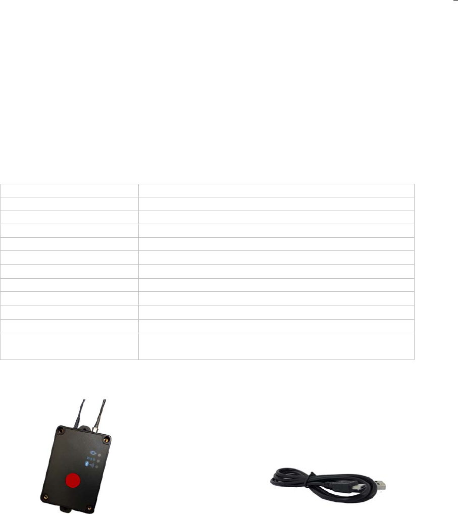
2、Product appearance and parameters
Items Specification
input voltage AC 100-240V 50/60HZ
Internal Battery Rechargeable lithium battery 100 mAh (3.7V)
Working current 450mA
size 83mm X 59mm X 35mm
weight 142g
Operating Temperature -20
~
+55
°C
GSM module Quad Band GSM 850/900/1800/1900 MHz
internal memory 32M-BIT Flash memory
LED Power
LED
li
g
ht、GSM
LED
li
g
ht
、wifi&BT
LED
li
g
ht
button SOS button
Antenna interface External antenna interface,for connect with 2.4GH
external antenna
accessories
GMT921Terminal(Internal Battery)
Special USB cable (optional)
2
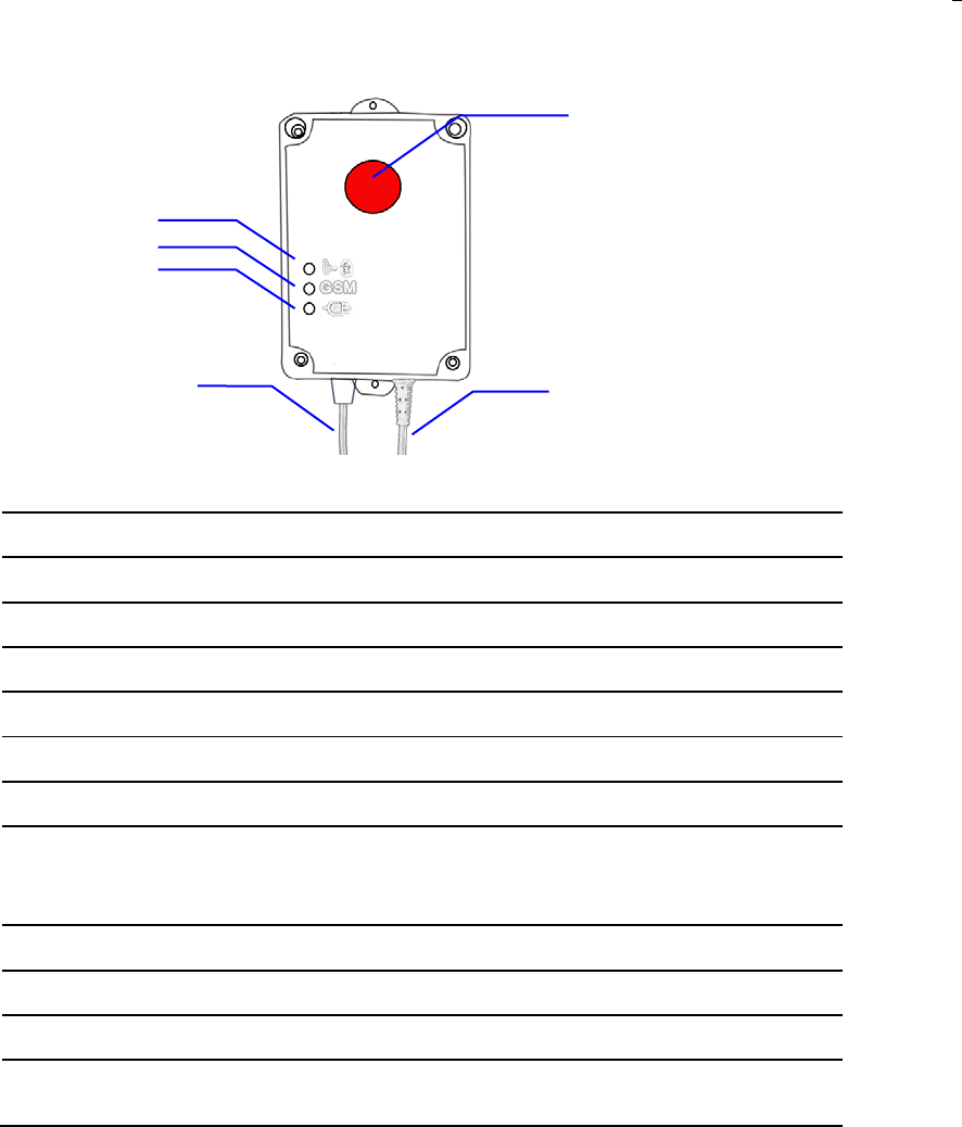
button
red – Power indication
always on Connect external power source
always off disconnect external power source
Blue – GSM indication
0.3s on and 0.3s off GSM module is initializing
Always on GSM network is not registered
1s on and 3s off GSM network is registered
0.1s on and 3s off GSM network is registered and connected to the server
by GPRS
yellow – GPS indication
1s on and 3s off module is initializing
0.1s on and 3s off module is working normally
SOS button Press sos button for 3S to sent” sos “alert to platform
3 function
◆power off alarm
1、When the home base unit is connected with power , the base unit will send alarm
information to the platform.
2、When the home base unit is disconnected with power , the base unit will send alarm
information to the platform.
***If the device has an power off alarm function, the device must be connected to an internal battery***
◆SOS emergency alarm
When Parole pressed the SOS key, the base unit sends an alarm message to the platform.
Power indication
GSM indication
Bluetooth &WiFi
SOS button
power cord
antenna
3
◆disassembly alarm
When the Home Base unit is disassembled, the base unit sends an alarm message to the
platform
◆ Heartbeat package
For keeping the base unit and the platform normal connection, the base unit transmits the
data to the platform according to the fixed time interval.
If the base unit does not send information to the platform according to the fixed time
interval, the base station and the platform are disconnected.
4the home base unit installation and use
Install the SIM card and spare battery for the home base unit
Install the card requirements
Ensure that your tracker has a working SIM card.
Please make sure SIM card has enough credit.
Please make sure that the SIM is not locked and do not require a password to operate.
If you need to make a phone call back to your location, Please make sure the SIM card is
supporting caller ID display
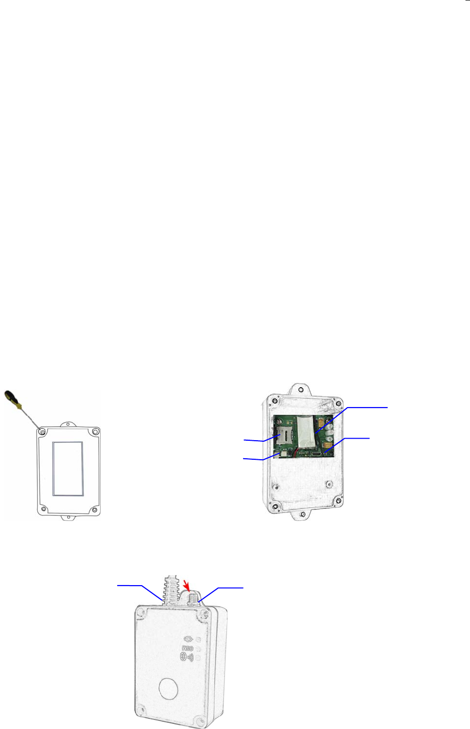
❶ ❷
1、Unscrew the back cover of the device. 2、Install the SIM card, insert the battery cable,
fixed the battery.
❸
Mini USB interface SIM card connector
Spare battery connector
Battery fixed position
antenna
power cord
4
3、 screwdriver screw on the back cover, and then install the antenna
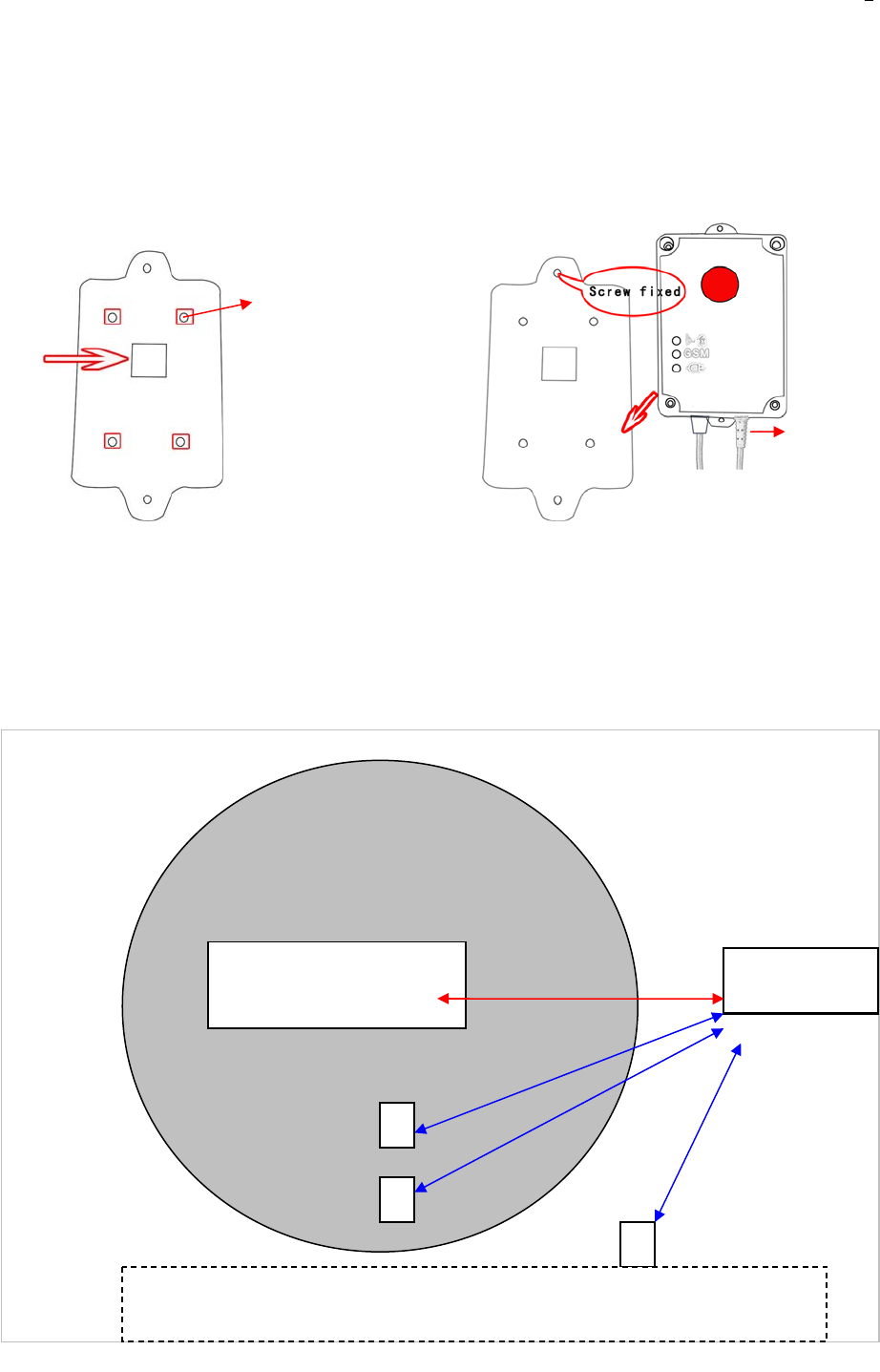
Fix the home Base unit
❶ ❷
Schematic diagram of the home base unit operation
The Home Base Unit
1
2
3
Platform
When the location fails, the tracker(1、2、3) uses the WIFI
function to search the home base unit.
(always in wireless transmit mode)
magnet
Connect with power
1、 the foundation of the home base unit with
screws fixed to the wall and put the magnet into
the specified location
2. The home base unit is screwed to the foundation
and Connect with
p
owe
r
.
fixed

5
5 Parameters set up
Tracker supports APP setup software by smart phone or by sending command via SMS or by
pc.
5.1 Change password
Description: change user’s password
SMS Command:$SMS,******;W001,######;!
SMS Command explain:$SMS,default password;W001,new password;!
Explain:
******: user password, the range of 6 digits, default password is 000000
######: new password, the range of 6 digits.
Note: please switch to the English input method when you input a command by smart phone;
tracker will only accept commands from a user with the correct password. Command will be
ignored if with wrong password.
Example:
$SMS,000000;W001,123456;!
Read password:$SMS,000000;R001;!
Clear password:$SMS,000000;C001;!
5.2、Set the GPRS server
Description: Enable this function
SMS Command:$SMS,000000;W002,APN,Username,Password;W003,IP,Port;W005,X;W009,Y;!
Explain:
APN: Access point name of
network range of: 0~29 characters
Username: accesses port’ user name range of: 0~29 characters
Password: Accesses port’s password range of: 0~29 characters
IP: server’ IP address range of: 0~29 characters
Port: server’s port range of: 0~65535
Y:
GPRS upload mode
range of: 0~2
0:means disable GPRS function,
1:means upload by TCP,
2:means upload by UDP
default is 0

6
Example:$SMS,000000;W002, cmnet,;W003,192.168.1.1,8088;W005,1;W009,1;!
Read tracking regulary by GPRS:
$SMS,000000;R002;R003;R005;R009;!
Clear tracking regulary by GPRS:
$SMS,000000;C002;C003;C005;C009;!
FCC Statement
This equipment has been tested and found to comply with the limits for a Class
B digital device, pursuant to part 15 of the FCC rules. These limits are
designed to provide reasonable protection against harmful interference in a
residential installation. This equipment generates, uses and can radiate radio
frequency energy and, if not installed and used in accordance with the
instructions, may cause harmful interference to radio communications.
However, there is no guarantee that interference will not occur in a particular
installation. If this equipment does cause harmful interference to radio or
television reception, which can be determined by turning the equipment off and
on, the user is encouraged to try to correct the interference by one or more of
the following measures:
-Reorient or relocate the receiving antenna.
-Increase the separation between the equipment and receiver.
-Connect the equipment into an outlet on a circuit different from that to which
the receiver is connected.
-Consult the dealer or an experienced radio/TV technician for help.
To assure continued compliance, any changes or modifications not expressly
approved by the party.
Responsible for compliance could void the user’s authority to operate this
equipment. (Example- use only shielded interface cables when connecting to
computer or peripheral devices).
This device complies with part 15 of the FCC Rules. Operation is subject to the
condition that this device does not cause harmful interference.
FCC Radiation Exposure Statement:
The equipment complies with FCC Radiation exposure limits set forth for
uncontrolled enviroment. This equipment should be installed and operated
with minimum distance 20cm between the radiator and your body.