ShenZhenKingsound Electronic CC2541-HY1 Bluetooth Module User Manual CC2541 HY1 Datasheet 20160302
ShenZhenKingsound Electronic Co., Ltd. Bluetooth Module CC2541 HY1 Datasheet 20160302
15_CC2541-HY1 UserMan
CC2541-HY1
DATA SHEET

TABLE OF CONTENTS
1 DESCRIPTION ...................................................................................................................2
2 APPLICATIONS ...................................................................................................................2
3 KEY FEATURES...................................................................................................................2
4 Pinout and Terminal..............................................................................................................3
5 Feedback IO output of the command................................................................................... 4
6 Bluetooth 4.0 host programming guide
6.1 instructions ....................................................................................................................5
6.2 Sends a packet length calculation .................................................................................5
7 Electrical Characteristics
7.1 Absolute Maximum Ratings ...........................................................................................5
7.2 Recommended Operating Conditions ............................................................................5
SHENZHEN KINGSOUND ELECTRONICS TECHNOLOGY CO., LTD.
CC2541-HY1 1 2014-05-12

HY1 Bluetooth® low energy single mode module
1,DESCRIPTION
HY1, Bluetooth low energy single mode module is a single mode device targeted for low power
sensors and accessories.
HY1 offers all Bluetooth low energy features: radio, stack, profiles and application space for
customer applications, so no external processor is needed. The module also provides flexible
hardware interfaces to connect sensors, simple user interfaces or even displays directly to the
module.
HY1 can be powered directly with a standard 3V coin cell batteries or pair of AAA batteries. In
lowest power sleep mode it consumes only 400nA and will wake up in few hundred
microseconds.
2,APPLICATIONS:
Bluetooth UART Module implementation of the connection with the tablet, IPHONE and
android mobile phone with Bluetooth 4.0, As far as the communication distance is in 20
m(linear) without sunscreen.
UART baudrate optional: (115200, 57600, 38400, 19200, 9600, 4800, 2400, 1200)
Work style: transparent way
Maximum send packet length: 128 BYTES
Maximum receive packet length: 128 BYTES
Application scope: equipment needs with the tablet, IPHONE, other android phones with
4.0 equipment to transport small data volume and low power consumption
3,KEY FEATURES:
Bluetooth v.4.0, single mode compliant
o Supports master and slave modes
Integrated Bluetooth low energy stack
o GAP, GATT, L2CAP, SMP
Bluetooth low energy profiles
Radio performance
o TX power: +3dBm to -23dBm
o RX sensitivity: -87dBm to 93dBm
Ultra low current consumption
o Transmit: 27mA (0dBm)
Sleep mode 3: 0.4uA
Programmable 8051 processor for embedding full applications
SHENZHEN KINGSOUND ELECTRONICS TECHNOLOGY CO., LTD.
CC2541-HY1 2 2014-05-12
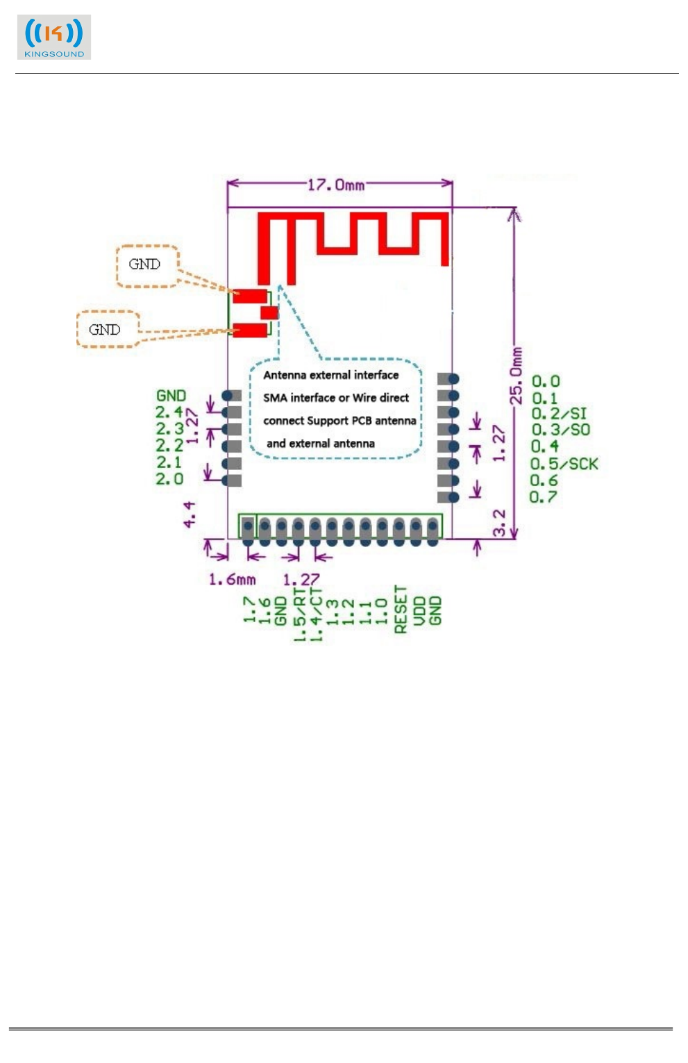
4,Pinout and Terminal
SHENZHEN KINGSOUND ELECTRONICS TECHNOLOGY CO., LTD.
CC2541-HY1 3 2014-05-12
5,Feedback IO output of the command:
RT (P1.7) can be used for receiving interrupt instructions, When there are the serial data
output or the output data in the buffer, to be low; or the serial buffer is empty, the output is high.
OT (P1.0) can be used for the indication if the data is sent to the BLE host (tablet, IPHONE),
OT is the high when executing the transmit data or waiting the data transmission, OT is low
when the data has been sent to the BLE host.
The input and output data:
No PINS Description
1 VDD 2.7-3.6V
2 TX (P1.5) Connect the RX side of the controller (Output Pin TTL)
3 RX (P1.4) Connect the TX side of the controller (Input Pin TTL)
4 GND GND
Power input, please try to reduce the ripple, so that can guarantee the communication distance
The input of data bytes must be continuous, Also the gap between the bytes sent time can't be
more than the time interval of corresponding baud rate. When (115200, 57600 and 57600 to 1 ms;
19200 to 2 ms; 9600 for 4 ms; 4800 for 7 ms; 2400 for 10 ms; 1200 to 15 ms) no data input, the
system will think that a packet of data reception is complete. Example: if the baud rate for 9600,
you need to transport the 16 byte bytes, a serial port serial input 16 bytes , after the 4 ms, the data
will begin to transfer to another module. If you want to transfer 1 byte, serial input, after finishing
the 1 byte transmission, after 4 ms, the data will begin to transfer to another module. Single
biggest bytes what can be sent is 128 BYTE. When transmission of bytes is 128 ,they will be sent
immediately.
The interval of time between the package is at least a connection, This time is by the BLE host.
No RT PIN (P1.7) STATUS
0 1 The serial buffer is empty
1 0 The serial data output or the output data in the buffer
No OT PIN (P1.0) STATUS
0 1 Executing the transmit data or waiting the data
transmission
1 0 The data has been sent to the BLE host.
SHENZHEN KINGSOUND ELECTRONICS TECHNOLOGY CO., LTD.
CC2541-HY1 4 2014-05-12
Establish a connection with BLE4.0 host (mobile phone, tablet, computer, etc.), light LED2,
otherwise shut off LED2
No (P0.1) LED2 output Light LED
0 0 Shut off
1 1 LED
This can be used as a indiction to judge the bluetooth BLE connection or not.
6 Bluetooth 4.0 host programming guide:
6.1 instructions
The module can transfer 128 byte packets at once, the intervals of the time between each
packet are by the package length and the interval time of the bluetooth connection, the
interval time of the bluetooth connection is setuped by BLE host (PC, IPHONE, the
ANDROID,support maximum time interval is 1000 ms, the minimum time interval for 100
ms).
6.2 Sends a packet length calculation
Connection interval for T (unit: ms), circulated a packet length Vt (ms), byte length L (byte).
Vt =(L / 80 ) * T + T
Note: (L / 80) add 1 if there is a decimal, such as L is 100 , so (L / 80) is equal to 2.
7 Electrical Characteristics
7.1 Absolute Maximum Ratings Note: These are absolute maximum ratings beyond which the
module can be permanently damaged. These are not maximum operating conditions. The maximum
recommended operating conditions are in the table 5.
Rating Min Max Unit
Storage Temperature -40 85 °C
VCC -0.3 3.9 V
Other Terminal Voltages VSS-0.4 VDD+0.4 V
Table 4: Absolute Maximum Ratings
7.2 Recommended Operating Conditions
Rating Min Max Unit
Operating Temperature Range -40 85 °C
VCC 2.0 3.6 V
*)Supply voltage noise should be less than 10mVpp. Excessive noise at the supply voltage will
reduce the RF performance.
Table 5: Recommended Operating Conditions
For the I/O terminal characteristic refer to the CC2541 datasheet
SHENZHEN KINGSOUND ELECTRONICS TECHNOLOGY CO., LTD.
CC2541-HY1 5 2014-05-12
Integrator is reminded to assure that these installation instructions
will not be made available to the end-user of the final host device.
The final host device, into which this RF Module isintegrated" hasto be labelled
with an auxilliary lable stating the FCC IDofthe RF Module,
such as "Contains FCC ID: "
"This device complies with part 15 of the FCC rules. Operation is subject to the following two
conditions:
(1)this devicemay not cause harmful interference, and
(2)this devicemust accept any interference received, including
interference thatmay cause undesired operation."
the Integrator will be responsible to satisfy SAR/ RF Exposure requirements,
when the module integrated into the host device.
NOTE: This equipment has been tested and found to comply with the limits for a Class B digital
device, pursuant to part 15 of the FCC Rules. These limits are designed to provide reasonable
protection
against harmful interference in a residential installation. This equipment generates, uses and can
radiate radio frequency energy and, if not installed and used in accordance with the instructions,
may cause harmful interference to radio communications. However, there is no guarantee that
interference will not occur in a particular installation. If this equipment does cause harmful
interference to radio or television reception, which can be determined by turning the equipment
off and on, the user is encouraged to try to correct the interference by one or more of the
following measures:
--Reorient or relocate the receiving antenna.
--Increase the separation between the equipment and receiver.
--Connect the equipment into an outlet on a circuit different from that to which the receiver is
connected.
--Consult the dealer or an experienced radio/TV technician for help.
Changes or modifications to this unit not expressly approved by the party responsible for
compliance could void the user's authority to operate the equipment.
2AKIWCC2541-HY1