Shin Chuan Computer SC700PDT-BWG Portable Data Terminal User Manual rev2
Shin Chuan Computer Co., Ltd. Portable Data Terminal rev2
Contents
- 1. Manual 1
- 2. Manual 2
Manual 2
3-21
C Type -- Others Barcodes
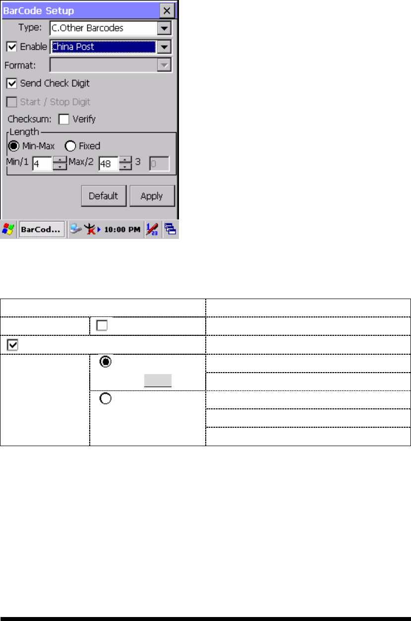
3.2.2.15 China Post
Figure 3-20 China Post
Table 3-18 China Post Explaining
Item Explaining
Checksum Verify Whether verify checksum by barcode.
Send Check Digit Whether send check digit by barcode.
Min Length can be set from 4 to 48
Min-Max
(Default: 4 / 48) Max Length can be set from 4 to 48
Length 1 can be set from 4 to 48
Length 2 can be set from 4 to 48
Length
Fixed
Length 3 can be set from 4 to 48
3-22
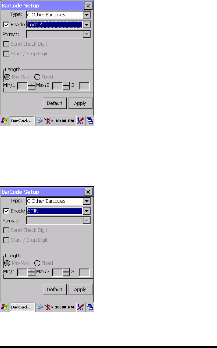
3.2.2.16 Code4
The barcode do not have setting.
Figure 3-21 Code4
3.2.2.17 GTIN
The barcode do not have setting.
Figure 3-22 GTIN
3-23
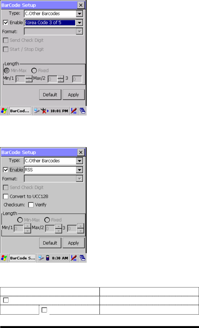
3.2.2.18 Korea Code 3 of 5
The barcode do not have setting.
Figure 3-23 Korea Code 3 of 5
3.2.2.19 RSS
Figure 3-24 RSS
Table 3-19 RSS Explaining
Item Explaining
Convert to UCC128
The scanner will convert RSS to UCC128.
Checksum Verify Whether verify checksum by barcode.
3-24
3.2.3 Bluetooth Device Properties
Table 3-20 Bluetooth Device Properties
ICON
ITEM & FUNCTION
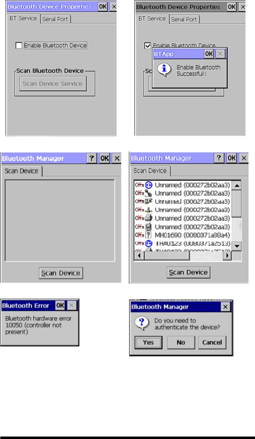
“BT Service” Tab ( Figure 3-25) :
Tap the “Enable Bluetooth Device” to enable Bluetooth device.
Wait for 20 seconds in order to initialize the Bluetooth hardware
correctly.
Click “Scan Device Service” to pop “Bluetooth Manager”
window. Then tap the Scan Device button to initiate a scan for
Bluetooth hardware. The Bluetooth manager lists the Bluetooth
devices that it finds, see Figure 3-26. If Bluetooth hardware is
not found the Bluetooth Hardware Error window appears, see
Figure 3-27. Table 3-21 described the Bluetooth Icons.
Double tap the device to connect to on the device list. The
Bluetooth Manager Authentication window appears. Tap No to
connect to the device without authentication, or tap Yes to
authenticate the device before connecting. (Figure 3-28)
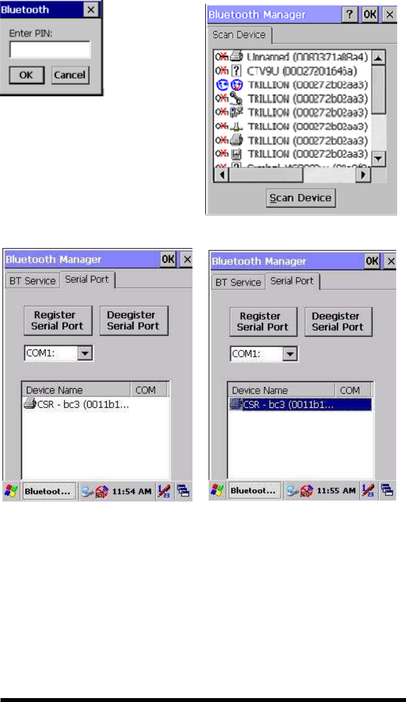
If the Yes button was selected in the Bluetooth Manager
Authentication window, the enter PIN windows appears. Enter a
PIN (between 1 and 16 characters) in the Enter PIN: text box,
and tap OK. The mobile computer sends the PIN request to the
device for bonding. (Figure 3-29)
When prompted, the same PIN must be entered on the other
device. When the PIN is entered correctly on the other device,
the bonded icon appears on the device list. (Figure 3-30)
“Serial Port” Tab ( Figure 3-30-1) :
Tap the “Enable Bluetooth Device” to enable Bluetooth device.
Wait for 20 seconds in order to initialize the Bluetooth hardware
correctly.
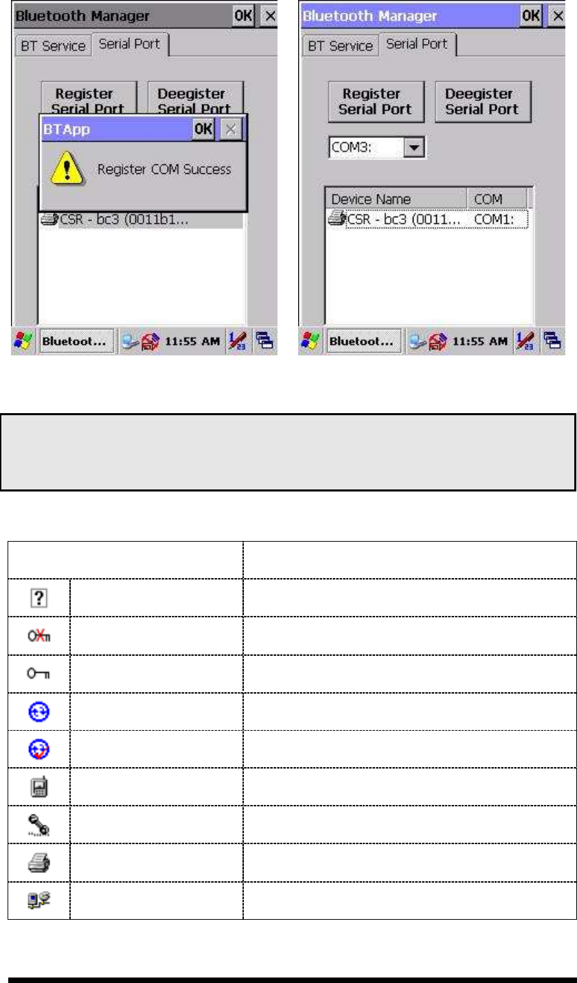
If want to use Virtual com, only SPP base profiles are
supported.(i.e. Printer, Modem, and LAP).Switch to “Serial
Port” tab, and will see the devices you had trusted or active.
Select the device that you want to map a virtual com and which
virtual com you want to use.
Now COM1 has mapped for BT device.
3-25
Figure 3-25 Bluetooth Device Properties Figure 3-25-1 Bluetooth Device Properties
Figure 3-26 Bluetooth Manager Windows Figure 3-26-1 Bluetooth Manager Windows
Figure 3-27 Bluetooth Error Windows Figure 3-28 Bluetooth Manager Windows
3-26
Figure 3-29 Bluetooth Enter PIN Windows Figure 3-30 Bluetooth Manager Windows
Figure 3-30-1 Bluetooth Manager Windows
Figure 3-30-2 Bluetooth Manager Windows
3-27
Figure 3-30-3 Bluetooth Manager Windows
Figure 3-30-4 Bluetooth Manager Windows
Note:
If the device to which the mobile computer is bonding does not appear in the list,
ensure it is turned on, in discoverable mode, and within range (30 feet / 10 meters) of the
mobile computer.
Table 3-21 Bluetooth Icon
Icon Description
Unknown device icon Device is not defined
Locked icon Device is locked and cannot be bonded to.
Not locked icon Device is not locked and can be bonded to.
Bluetooth device icon Bluetooth device
Bonded device icon Bonded Bluetooth device
Mobile device icon Device is a mobile device
Phone icon Device is a phone.
Printer icon Device is a printer
Network icon Device is a network.

3-28
Icon Description
Linked icon Device is linked.
3.2.4 Certificates
Certificates are used by some applications for establishing trust and for secure
communications.
Certificates are signed and issued by certificate authorities and are valid for a
prescribed period of time. Windows CE manages multiple certificate stores.
Table 3-22 Certificates
ICON
ITEM & FUNCTION
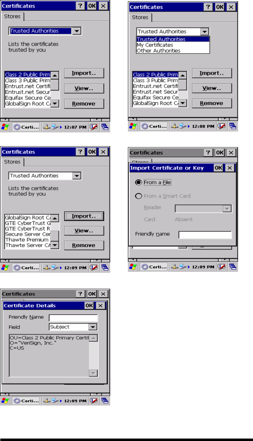
“Store” Tab ( Figure 3-31) :
In the Stores tab, select the certificate store you wish to view or
modify from the drop-down list (Figure 3-32).
The “Trusted Authorities “store lists the top-level certificates
for authorities you trust.( Figure 3-33 , Figure 3-34)
The “My Certificates “store contains your personal certificates,
which you use to identify yourself.
Intermediate certificate authorities that help establish a chain of
trust are stored in the “Other Authorities” store.
“Store” Tab :
To add a certificate or associated private key to the selected
store, select “Import” (Figure 3-35).
To view more details of the selected certificate, such as the
expanded name or expiration date, choose “View”.
To delete the selected certificate from the store, choose
“Remove”.
3-29
Figure 3-31 Certificates Figure 3-32 Certificates
Figure 3-33 Certificates
Figure 3-34 Certificates
Figure 3-35 Certificates
3-30
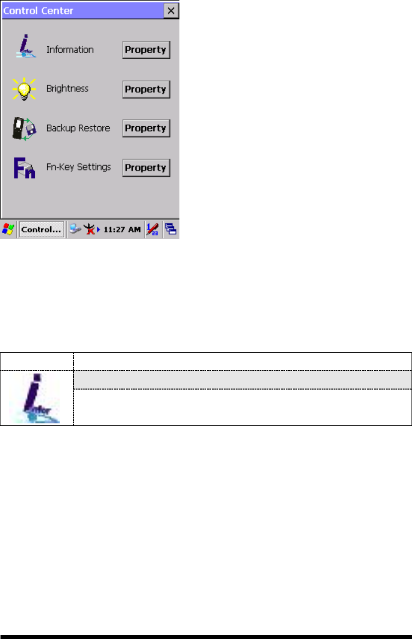
3.2.5 Control Center
The Control Center includes four AP, listed the following ......
Figure 3-36 Control Center
3.2.5.1 Information
Table 3-23 Information
ICON ITEM & FUNCTION
“Information” Tab :
Provide Software version, MAC address, Bluetooth ID, Serial
No. and Configuration No.
3-31
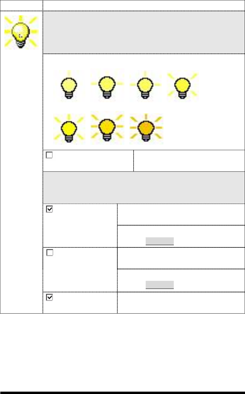
3.2.5.2 Brightness
Table 3-24 Brightness
ICON ITEM & FUNCTION
LCD Brightness
Tune the LCD brightness by tapping right-arrow & left-arrow. Can
also tune the LCD brightness by pressing right-direction key or
left-direction key of keypad.
Amounts 7 steps: Every step have corresponding picture of self.
1. 2. 3. 4.
5. 6. 7.
Enable Keypad
Brightness
Open keypad brightness or not.
Backlight Timeout
Save battery life by automatically turning off the backlight when not
used.
The table must disable when its item is not
marked.
Battery Power, turn
off backlight after
The table has 15 seconds, 30 seconds, 1
minute, 2 minutes and 5 minutes.
The table must disable when its item is not
marked.
AC Power, turn off
backlight after
The table has 15 seconds, 30 seconds, 1
minute, 2 minutes and 5 minutes.
Dim backlight
after
20 seconds of idleness.
Save battery life functionally of idleness
mode, open it or not.
3-32
Figure 3-37 Brightness
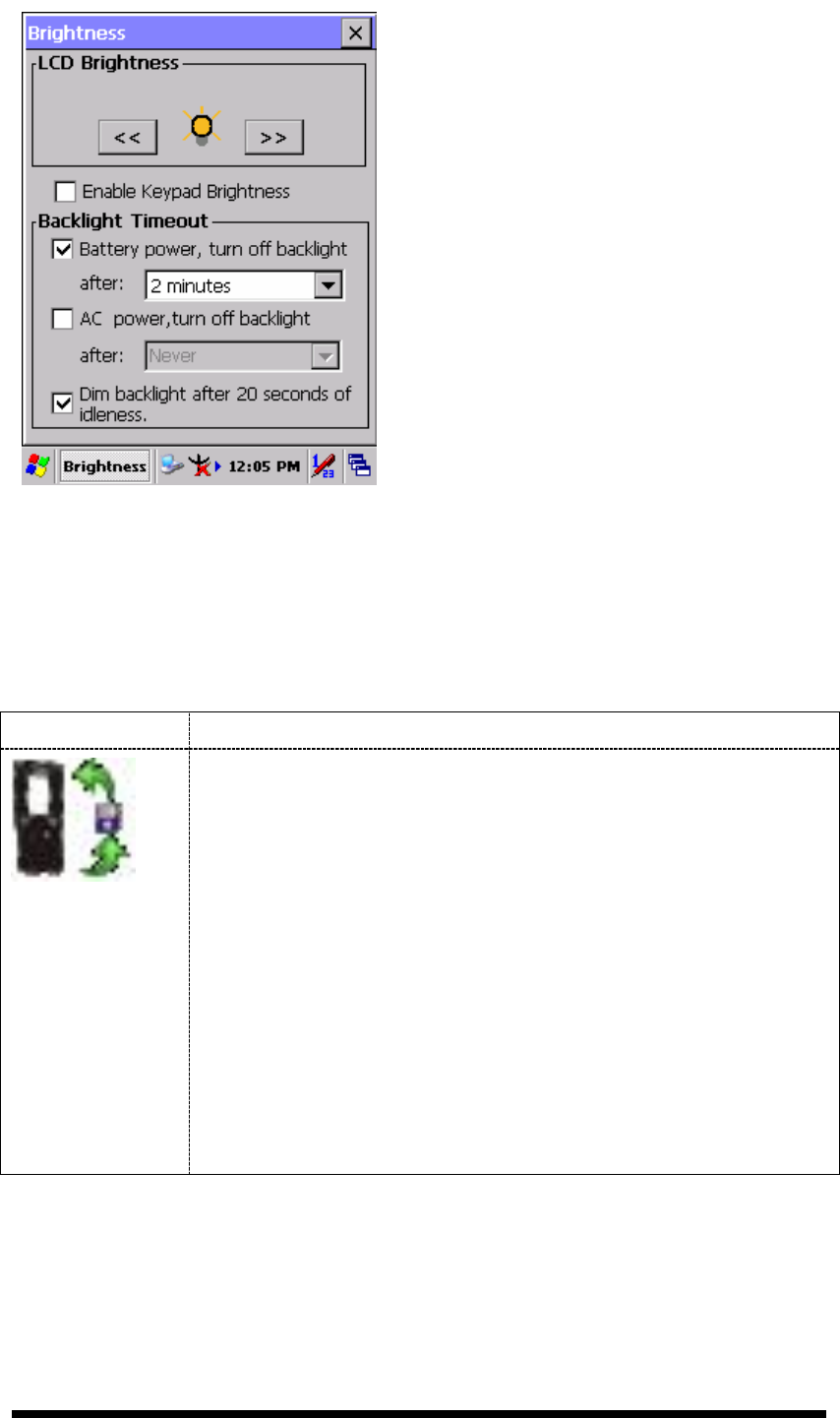
3.2.5.3 Backup Restore
Table 3-25 Backup Restore
ICON ITEM & FUNCTION
1. You can backup/restore system to/from flash disk or inserted
memory card. (A. Disk on Chip, B. CF Card, C. SD Card)
( Figure 3-38)
2.
When you launch this AP, it must check backup file in DOC
first. And if you select other storage, it will check again.
3. Then if it has the file, appeared its date behind “Last backup
date:”; if not, disable “Restore Now” Button.
4. When you press the Backup/Restore Button will be a warning
dialog pop up. ( Figure 3-39)
5. When system backup/restoring finished will be a message
dialog will pop up. (A. Backup: Figure 3-40, B. Restore: Figure
3-41)
3-33
Figure 3-38 Backup Restore
Figure 3-39 Backup & Restore Start
Figure 3-40 Backup OK
Figure 3-41 Restore OK
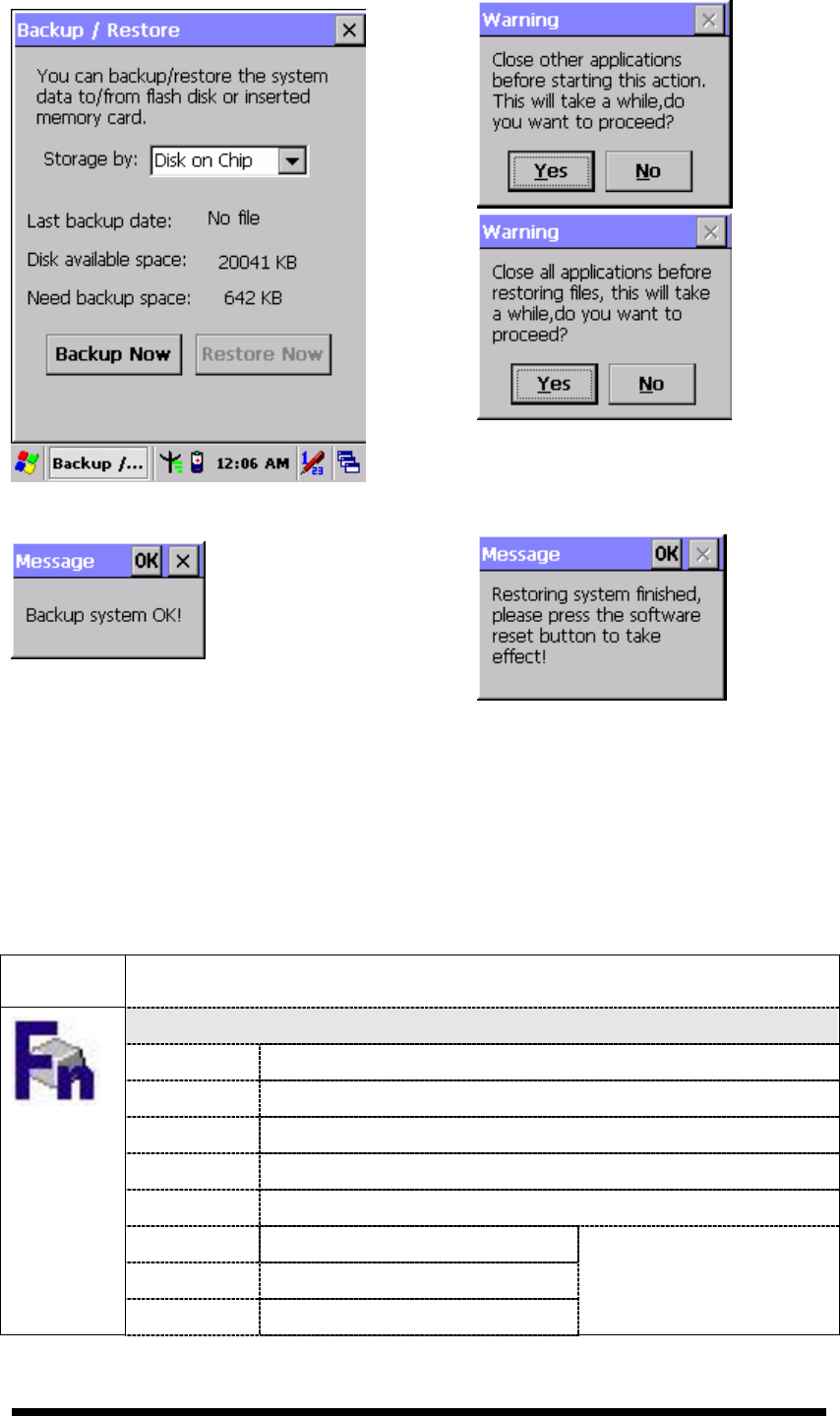
3.2.5.4 Fn-key Settings
Table 3-26 Fn-Key
ICON
ITEM & FUNCTION
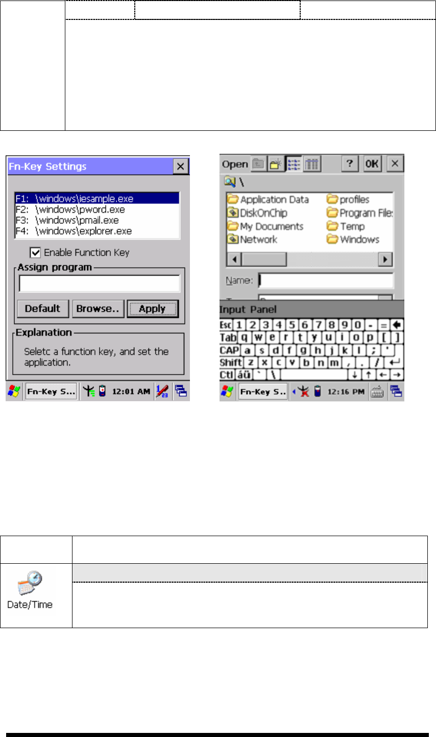
Fn-Key Setting (Figure 3-42)
Fn Key The Application Program of default setting
F1 Internet Explorer
F2 Microsoft WordPad
F3 Inbox
F4 My Computer
F5 Barcode Settings
F6 Media Player
F7 Calculator
Only for SC720
3-34
F8 Information
To assign your favorite application program to Hot Keys.
Choose one of Hot Keys from pull-down list.(Figure 3-43)
To tap “Browse…” inside “Assign program” applet.
Select one application program you want from program list, then,
choose “OK”. (Figure 3-43)
To tap “Default” to return back to default setting. (Figure 3-42)
Figure 3-42 Fn-Key Settings Figure 3-43 Fn-Key Settings
3.2.6 Date/Time
Table 3-27 Date/Time
ICON
ITEM & FUNCTION
“Date/Time” Tab :( Figure 2-14)
Please see the detail information of 2.5.1 Setting Time and
Date on P.2-21

3-35
3.2.7 Dialing Properties
Table 3-28 Dialing properties
ICON
ITEM & FUNCTION
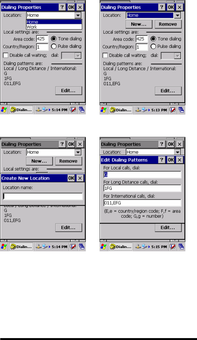
“Dialing Properties” Tab :( Figure 3-44)
In the When dialing from list, select the “Location” where you
want to change settings.(Figure 3-45)
To create a new location, select “New”. Enter the name of the
location, and then select “OK”.(Figure 3-46)
Enter or edit the area code and local country code as needed.
In Dial using, select “Tone dialing” or “Pulse dialing”. Most
phone lines are tone.
To automatically disable call waiting, select “□
□□
□ Disable call
waiting by dialing”, select the appropriate number sequence in
the list, or enter a new sequence.
Editing dialing patterns (Figure 3-47)
Using the codes listed in the topic; revise the dialing patterns as
needed.
Notes:
If you need to use character other than the ones listed here,
use manual dialing.
Hyphens and spaces in dialing strings are ignored.
Some modems may not respond to the following characters,
even though your device lets you add them to the dial
string.
3-36
Figure 3-44 Dialing Properties Figure 3-45 Dialing Properties
Figure 3-46 Dialing Properties Figure 3-47 Dialing Properties
3-37
3.2.8 Display Properties
Table 3-29 Display properties
ICON
ITEM & FUNCTION
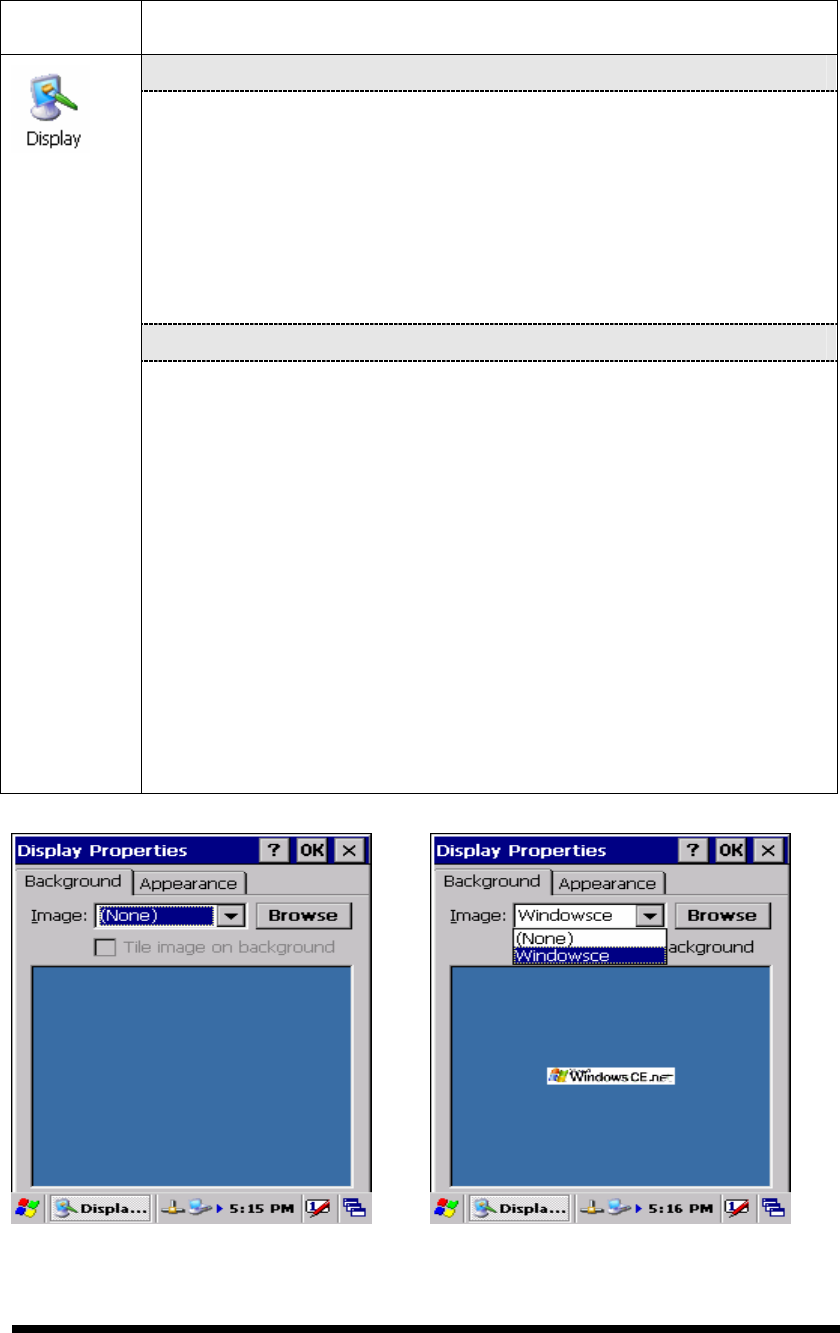
“Background” Tab :( Figure 3-48)
From the “Image” list, select an image you want as the
background of the desktop.(Figure 3-49)
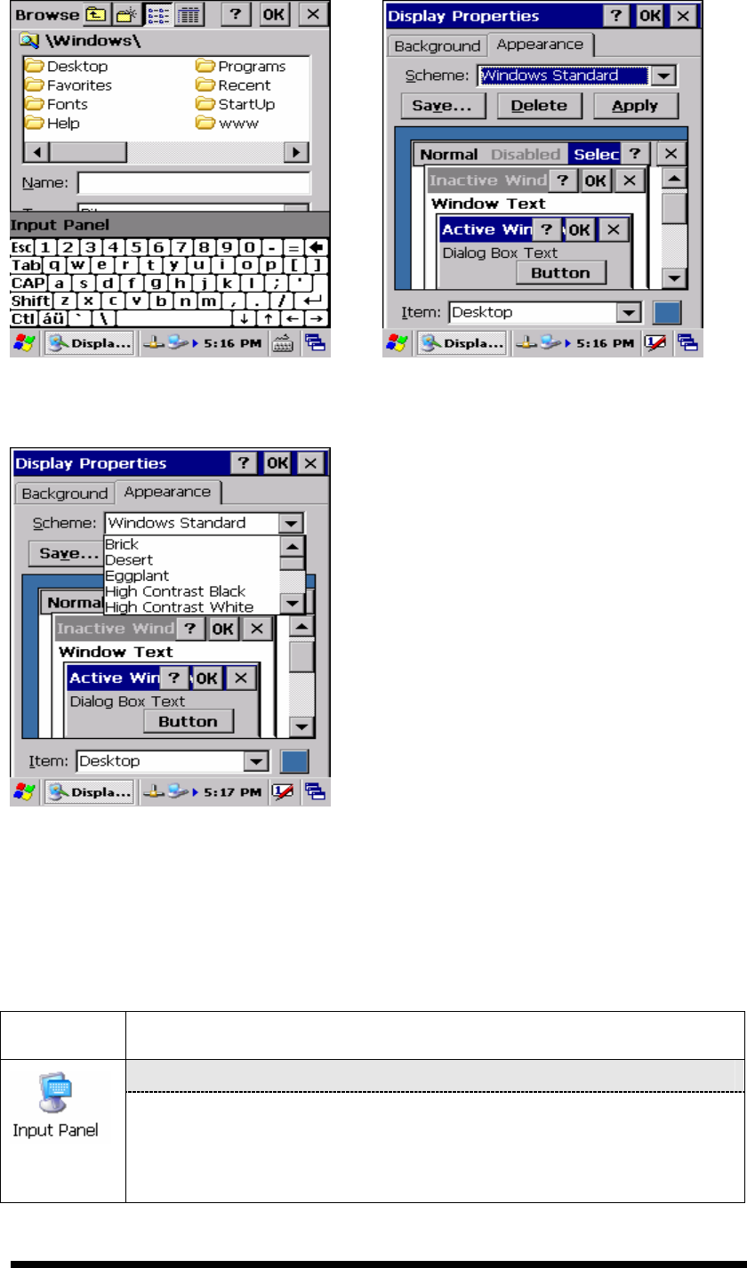
To locate an image in another folder, select “Browse”.(Figure
3-50)
To have the image cover the entire background, select “ □
□□
□Tile
image on background”
“Appearance” Tab(Figure 3-51)
Change the color scheme :( Figure 3-52)
From the” Scheme” list, select a scheme.
View your choice in the preview box. If you like the scheme,
select “Apply”.
Create a custom color scheme:
From the “Item” list, select a display item.
From the “Basic colors” list, select a color, and select “OK”.
View your color selection(s) in the Preview box.
To save the scheme, select “Save”.
In the “Save this color scheme as” box, enter a name for the
scheme, and select “OK”.
Select “Apply”.
Figure 3-48 Display properties Figure 3-49 Display properties
3-38
Figure 3-50 Display properties Figure 3-51 Display properties
Figure 3-52 Display properties
3.2.9 Input Panel
Table 3-30 Display properties
ICON
ITEM & FUNCTION
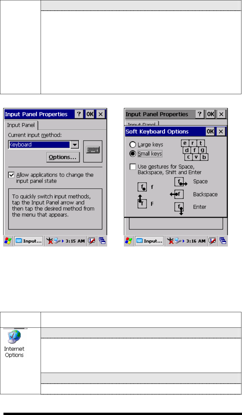
“Input panel” Tab :( Figure 3-53)
Select the input method you want to change.
To change the Soft Keyboard Options , tap “Option” (Figure
3-54) .
3-39
“Options” Tab :
Change the soft keyboard options as desired, selecting from:
Large or small keys
Using gestures for space, black-space shift, and enter.
To exit the soft keyboard Options, press “OK” on the control
bar, or press the <Enter> key on the keypad.
To exit the Input Panel, press “OK” on the control bar, or press
the <Enter> key on the keypad.
.
Figure 3-53 Input Panel Properties Figure 3-54 Input Panel Properties
3.2.10 Internet Options
Table 3-31 Internet Options
ICON
ITEM & FUNCTION
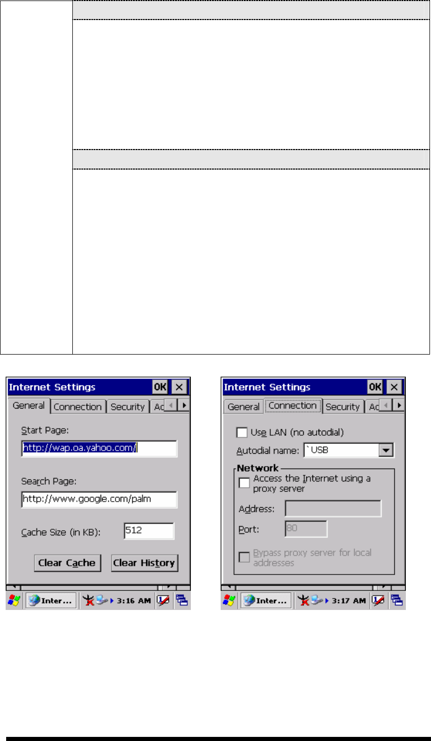
“General” Tab :( Figure 3-55)
Type in the URL of desired start page and the desired search
engine. You also change the Cache Size, clear the Cache and
Clear the History..
“Connection” Tab :( Figure 3-56)
Modify the network access setting as desired.
3-40
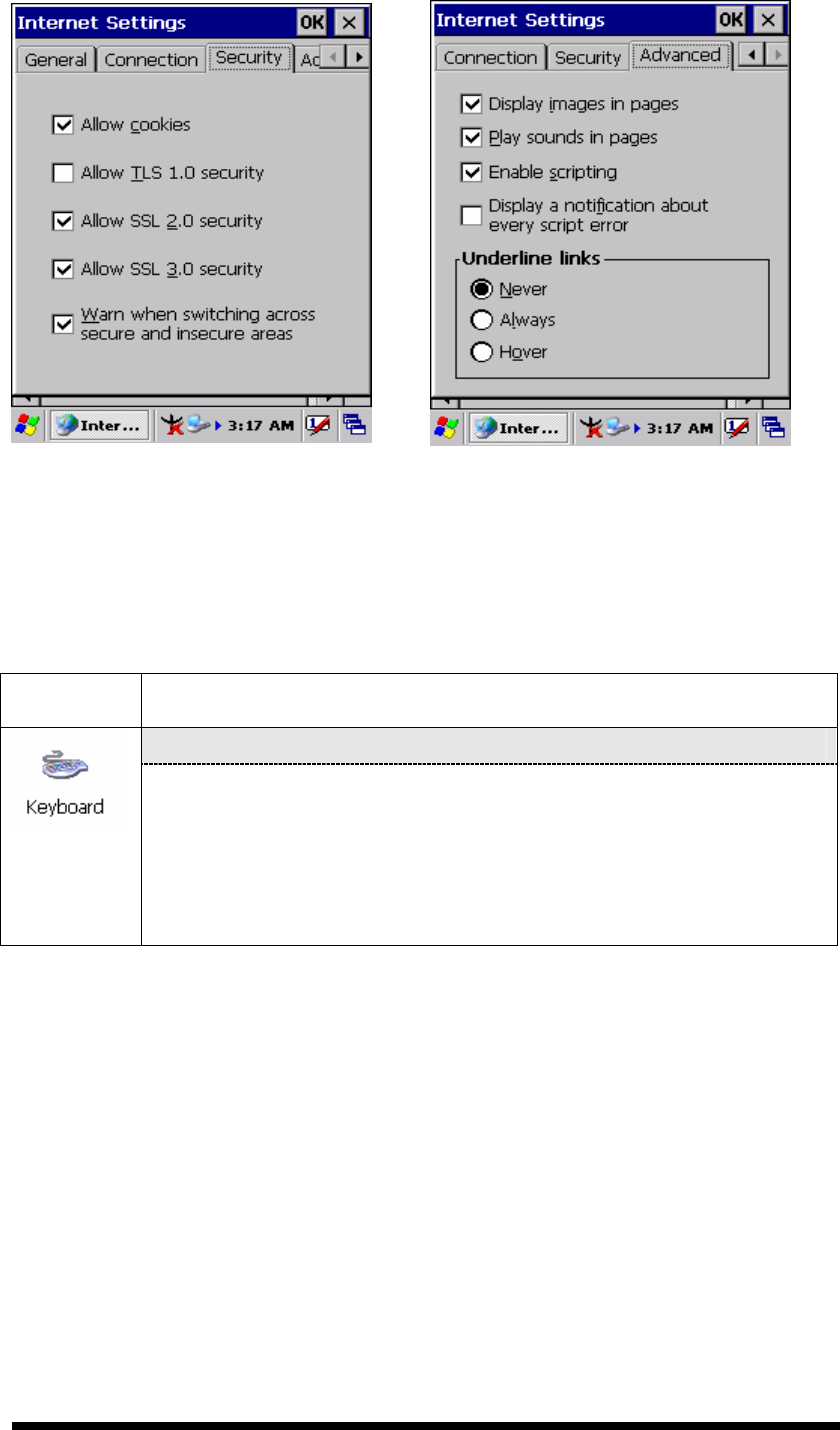
“Security” Tab (Figure 3-57)
Modify the security settings as desired. You can enable any of
the following by tapping the checkbox:
Allow cookies
Allow TLS 1.0 security
Allow SSL 2.0 security
Allow SSL 3.0 security
Warm when switching across secure and insecure areas.
“Advanced” Tab (Figure 3-58)
Modify the security settings as desired. You can enable any of
the following by tapping the checkbox:
Display Image in pages
Play sounds in pages
Enable scripting
Display a notification about every script error
Underline links-
○
Never
○
Always
○
Hover
Figure 3-55 Internet Settings Figure 3-56 Internet Settings
3-41
Figure 3-57 Internet Settings
Figure 3-58 Internet Settings
3.2.11 Keyboard
Table 3-32 Keyboard
ICON
ITEM & FUNCTION
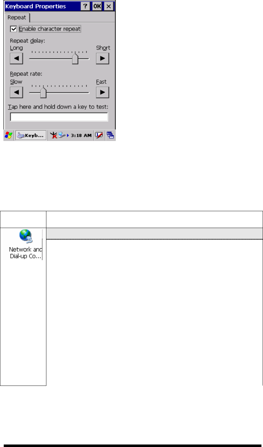
“Repeat” Tab :( Figure 3-59)
To change the amount of time between depressions before
repetition starts, adjust the Repeat delay slider
To change the repeat rate, adjust the Repeat rate slider.
Test your new setting.
Tap “ OK” to exit the “Keyboard” Tab.
3-42
Figure 3-59 Keyboard Properties
3.2.12 Network and Dial-up Connections
Table 3-33 Network and Dial-up Connections
ICON
ITEM & FUNCTION
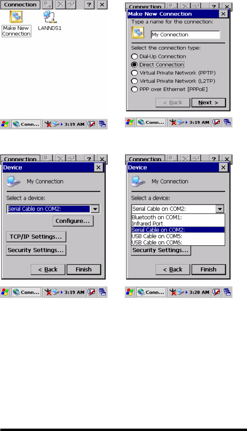
“Connection” Tab :
To create a “Dial-up Connection”:
Double-tap the “Make New connection”.
In the “Make New Connection” dialog box, enter a name for
the connection.
Select “Dial-Up Connection”.
Select the “Next” button.
Select the modem you want use.
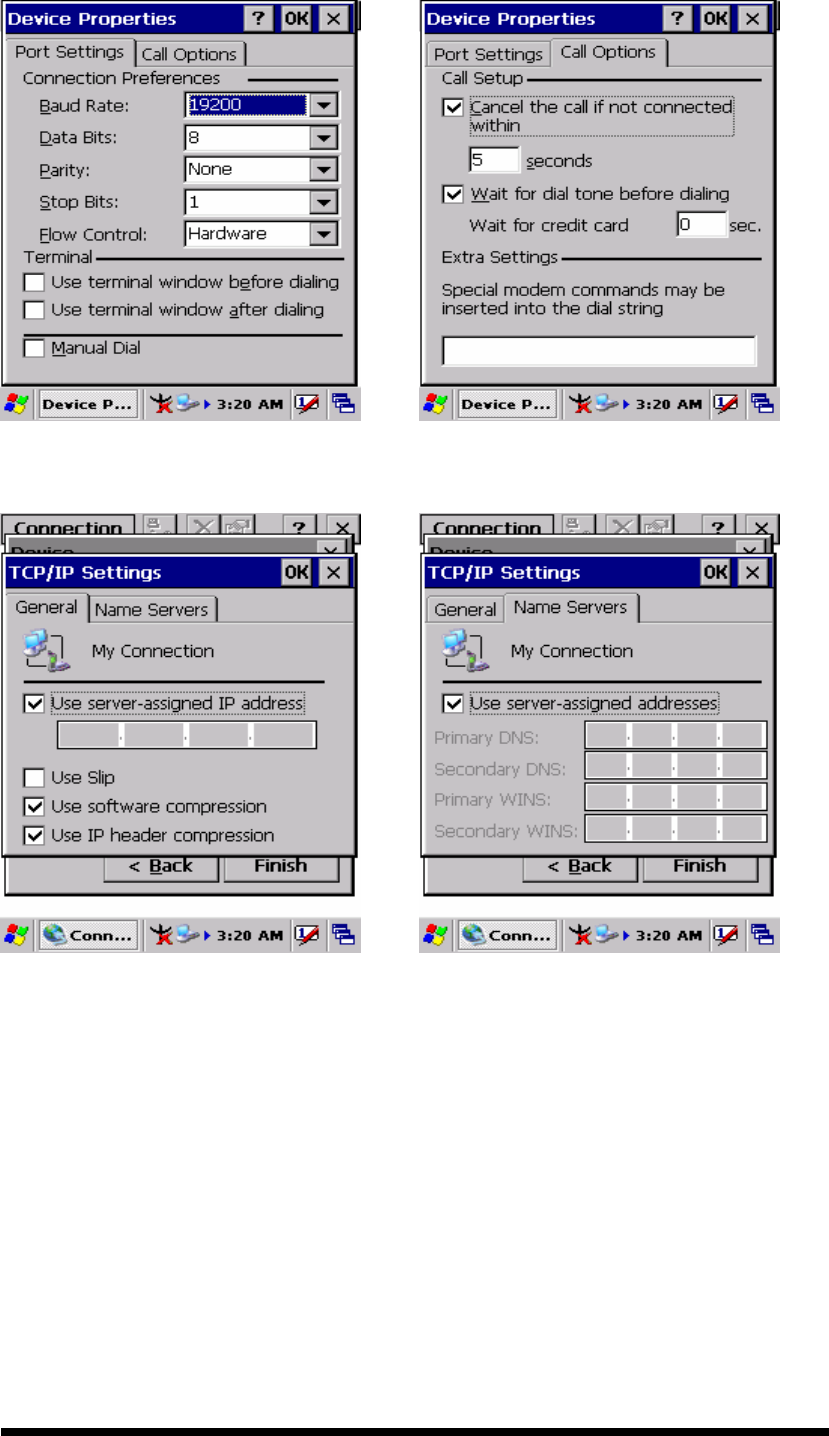
Select “Configure”
Under “Connection Reference”, use the default settings
provided. If you can’t connect using these settings, see your
ISP or network administrator for specific information. If you
want to always enter a phone number before connecting,
Select “Manual Dial”. Select “OK”.

3-43
Select “TCP/IP Settings”. In the “General” tab, ensure “Use
Server-assigned IP address” is selected. In the “Name
Servers” tab, ensure “Use Server-assigned addresses” is
selected, and select “OK”. If you are unable to connect with
these default settings, see your ISP or network administrator
for specific TCP/IP information.
Select the “Next” button and type the telephone number.
Select the “Finish” button.
The connection you just created appears as an icon in the “Network
and Dial-up Connections” folder.
Set up a point-to-Point Protocol(PPP) account with an ISP and
obtain the following information:
Access telephone number
User name
Password
Once you have established an account, create a new connection on
your device. When creating this connection, you should be able to use
all of the default TCP/IP settings provided in the Make New
Connection Wizard. If you can’t connect using the default settings,
contact your ISP or access your ISP’s Web site for specific TCP/IP
information as well as primary and secondary DNS address.
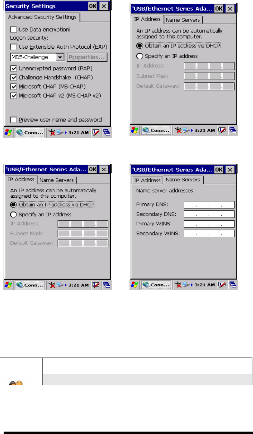
Modify connection setting
Select Start > Settings > Network and Dialup Connections
Select the icon for connection settings you want to modify.
Select File > Properties, or double- tap the appropriate icon.
Select desired options. There may be additional settings that
depend on the connection. To modify, select the icon and
select the icon and select Advanced Settings… from the
menu.
3-44
Figure 3-60 Network and Dial-up Connections
Figure 3-61 Network and Dial-up Connections
Figure 3-62 Network and Dial-up Connections
Figure 3-63 Network and Dial-up Connections
3-45
Figure 3-64 Network and Dial-up Connections
Figure 3-65 Network and Dial-up Connections
Figure 3-66 Network and Dial-up Connections
Figure 3-67 Network and Dial-up Connections
3-46
Figure 3-68 Network and Dial-up Connections
Figure 3-69 Network and Dial-up Connections
Figure 3-70 Network and Dial-up Connections
Figure 3-71 Network and Dial-up Connections
3.2.13 Owner
Table 3-35 Owner
ICON
ITEM & FUNCTION
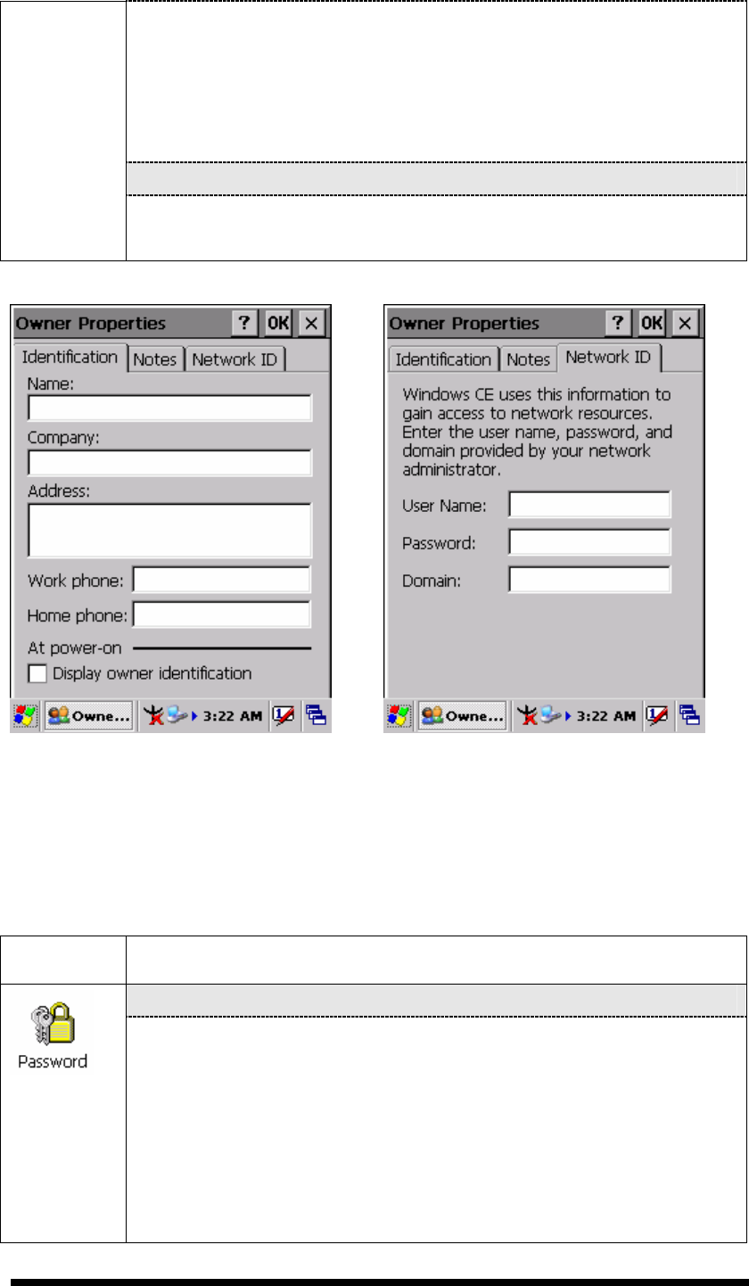
“Identification” Tab : (Figure 3-72)
3-47
Fill in or edit the data as desired.
To have this information displayed when you start your device,
select “Display Owner Identification” at Power On.
To set up identification for remote networks, see Setting up
identification for remote networks.
“Network ID” Tab: (Figure 3-73)
Enter the user name, password, and domain name you use to log
on to remote network.
Figure 3-72 Owner Properties Figure 3-73 Owner Properties
3.2.14 Password
Table 3-36 Password
ICON
ITEM & FUNCTION
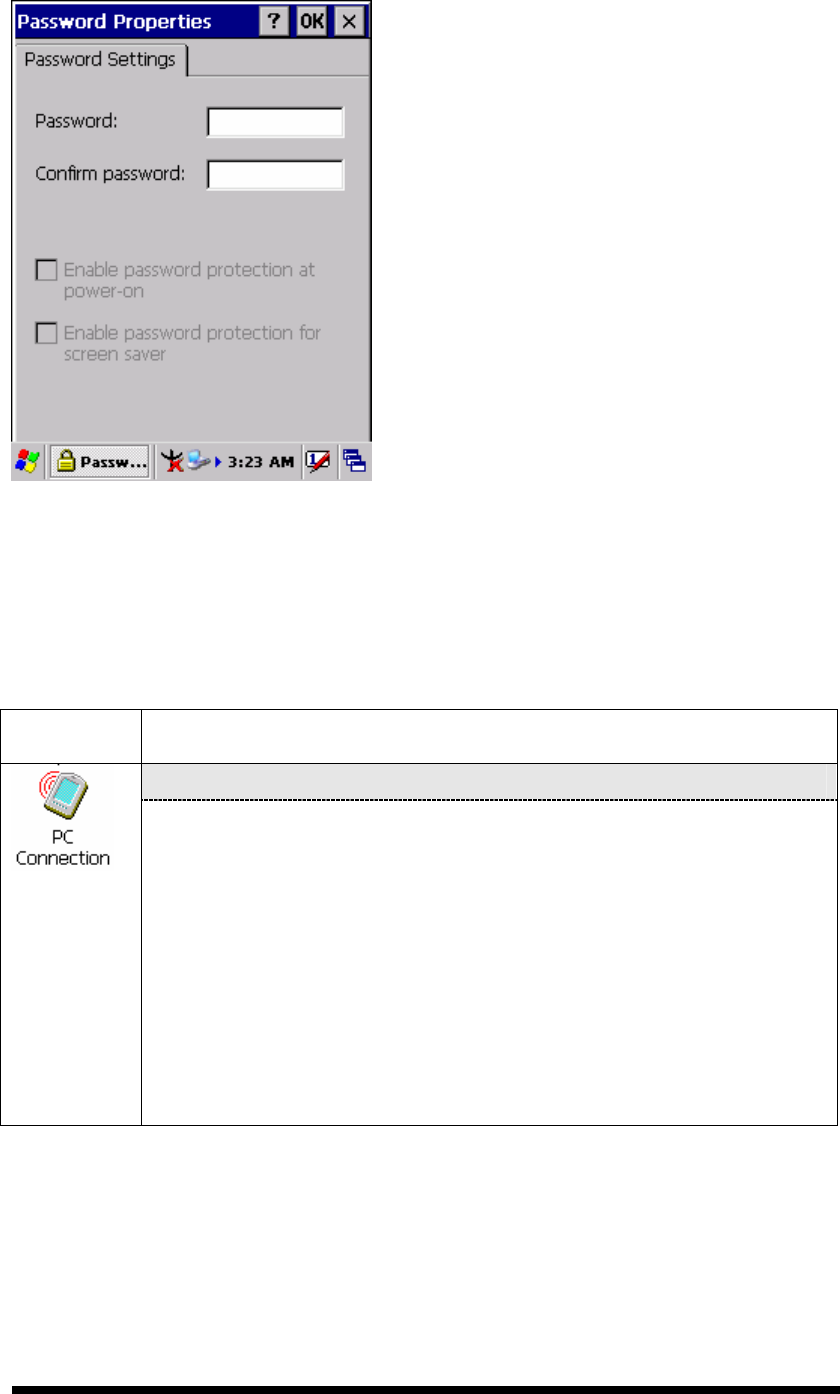
“Password Setting” Tab : (Figure 3-74)
Enter the password
In the “Confirm password “box, enter the password again.
To require the password on startup, select “Enable password
protection at power- on“. and/or select “Enable password
protection for screen saver”
To exit the Password control panel, press “OK” from the
control bar, or press the <Enter> key on the keypad.
3-48
Figure 3-74 Password Properties
3.2.15 PC Connection
Table 3-37 PC Connection
ICON
ITEM & FUNCTION
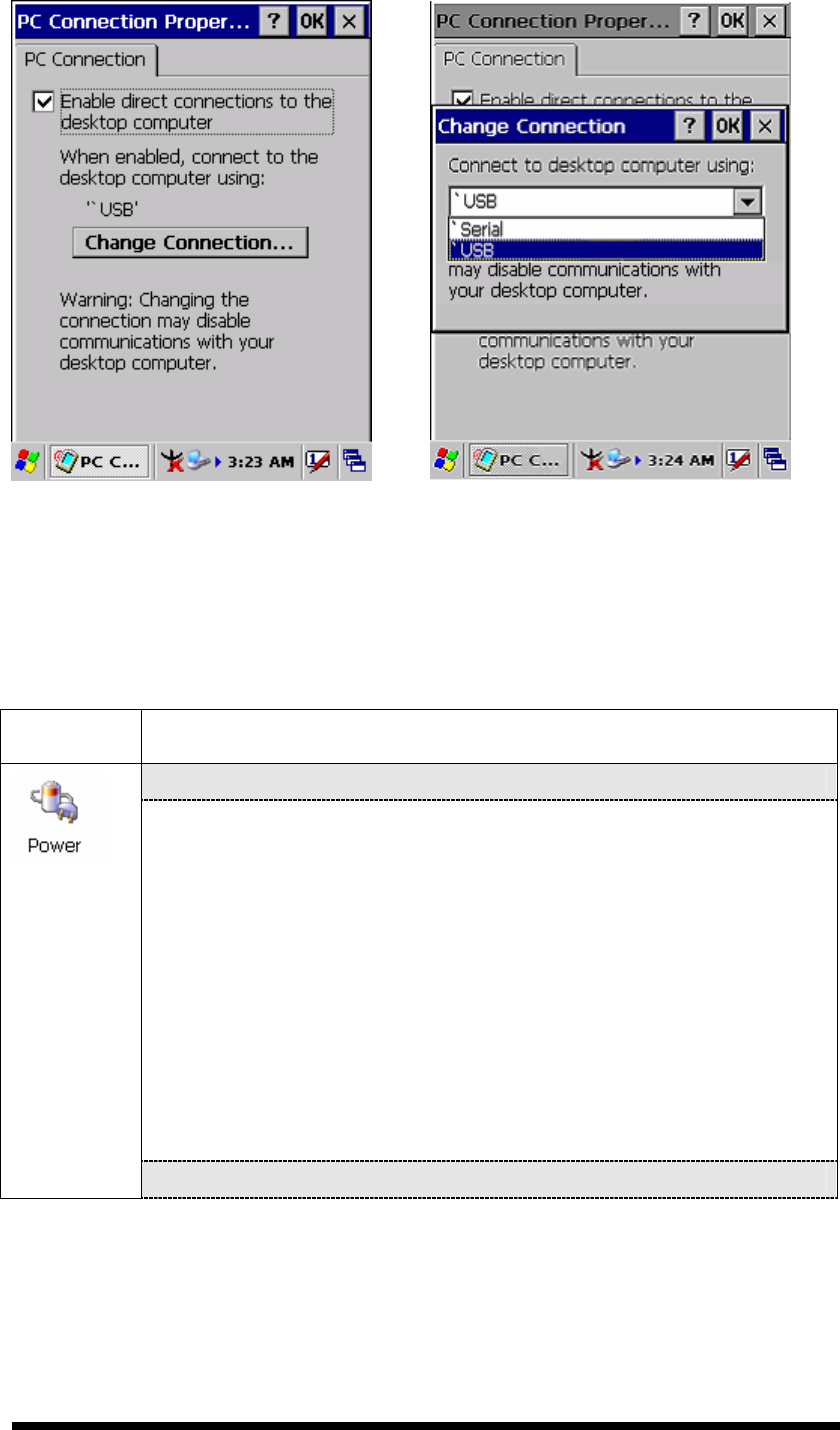
“PC Connection” Tab : (Figure 3-75)
Select the first checkbox to enable direct connections to the
desktop computer. (Figure 3-75)
Tap the “Change Connection…” button to modify the
connection method from USB or Serial. (Figure 3-76)
To exit the “Change Connection” dialog, press “OK” from the
control bar, or press the <Enter> key on the keypad.
To exit the “PC Connection” properties control panel, press
“OK” from the control bar, or press the <Enter> key on the
keypad.
3-49
Figure 3-75 PC Connection Figure 3-76 PC Connection
3.2.16 Power
Table 3-38 Power
ICON
ITEM & FUNCTION
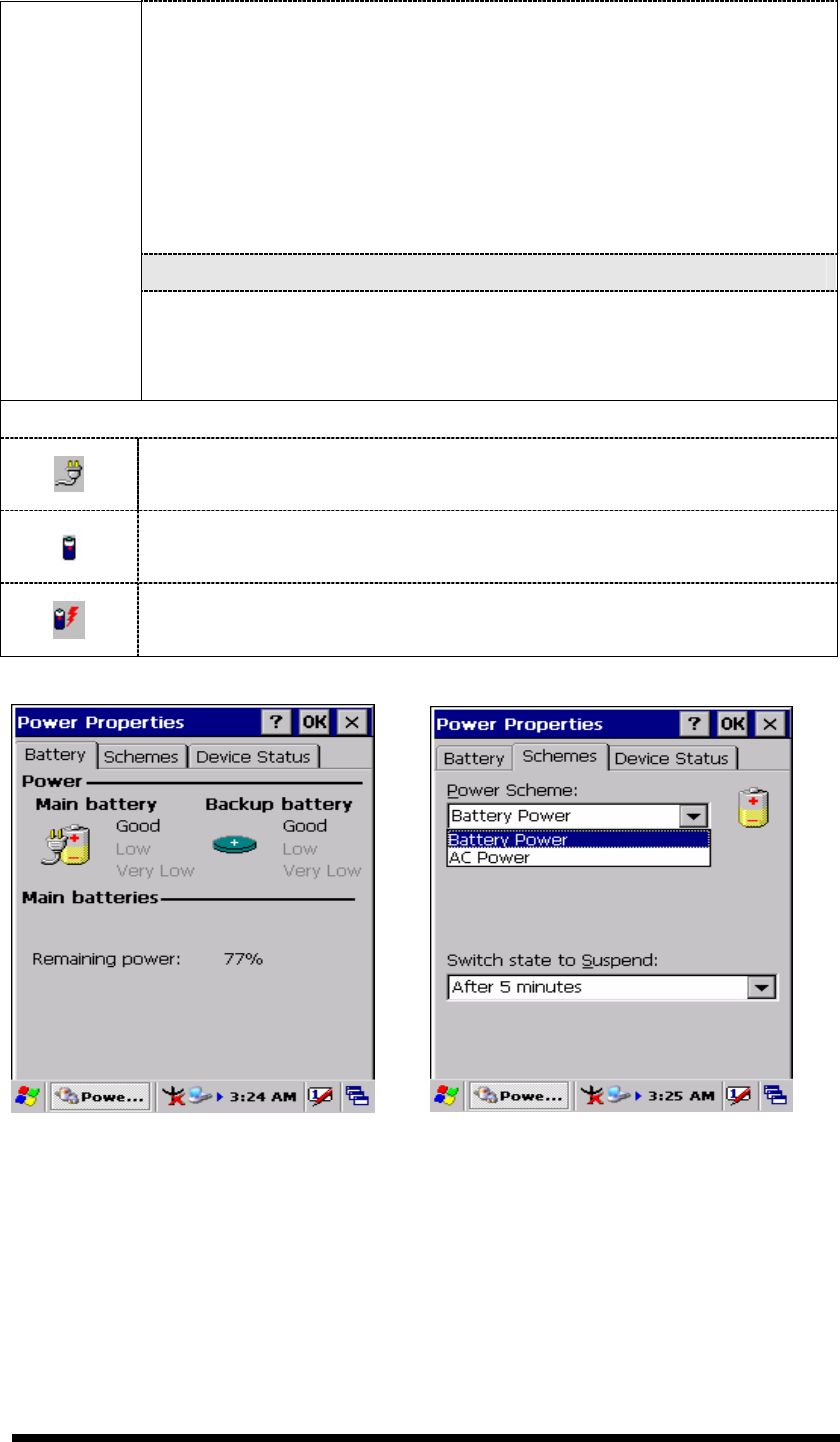
“Battery” Tab : (Figure 3-77)
Provide change level indicators for Main battery and Backup
battery.
Provide remaining power capacity of main battery.
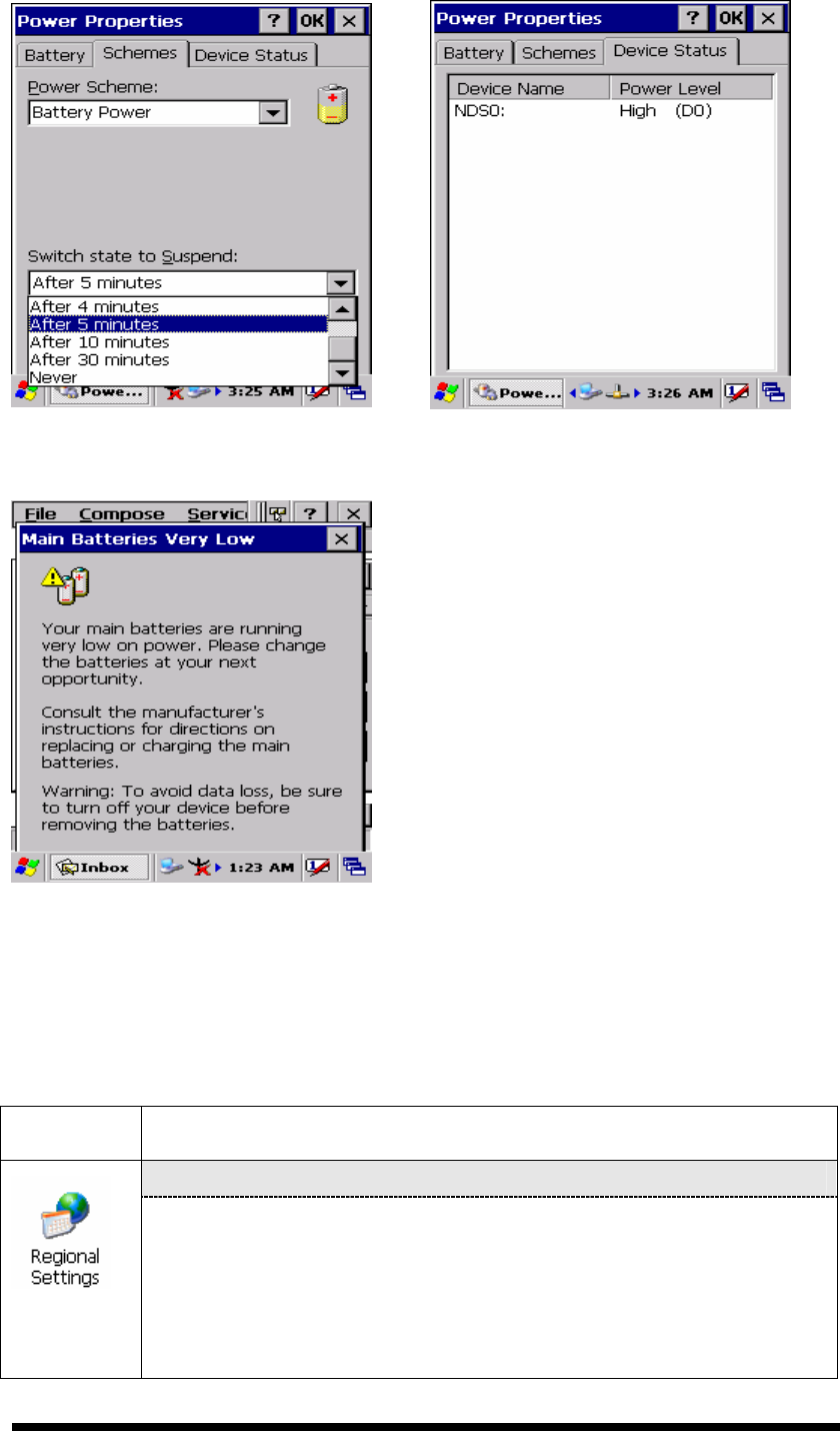
If a “Main Batteries very Low” warning message shows, the
remaining battery life is around 30 minutes to SC700 shuts
down. ( Figure 3-81)
The PDT will shutdown during the main batteries capacity is
around 0%
To exit Battery control panel, press “OK” from the command
bar, or press <Enter> key on keypad.
“ Schemes” Tab: (Figure 3-78)
3-50
The Scheme Tab allows you to determine the time to switch
state to Suspend mode when using either Battery Power or AC
Power.
Select Battery Power or AC Power as the power scheme from
the pull-down list.( Figure 3-78)
Select the time to suspend mode from the pull-down list.
( Figure 3-79)
“Device Status” Tab: ( Figure 3-80)
Provide power level of device – The power level ranges from
“ High(D0)” which means the device is at the highest power level to
“Off(D4)” which means the device is at the lowest power level.
Note:
This ICON inside the Task Bar shows that AC adapter provides power
to the PDT
The ICON inside the Task Bar shows that Main Batteries provides the
power to the PDT.
The ICON inside the Task Bar shows that AC adapter provides the
power to the PDT and is charging the main batteries..
Figure 3-77 Power Figure 3-78 Power
3-51
Figure 3-79 Power Figure 3-80 Power
Figure 3-81 Power
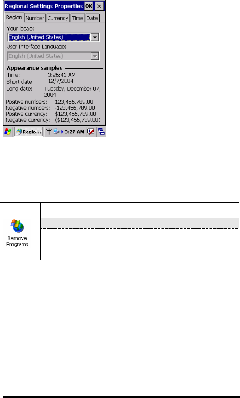
3.2.17 Regional Settings
Table 3-39 Regional Settings
ICON
ITEM & FUNCTION
“Region” Tab : (Figure 3-82)
Select the desired location/language.
Review the Appearance samples in the bottom half of the
screen.
Select the Tab at the top for any settings you wish to change,
Options to modify include Number, Currency, Time, and Date.
3-52
Figure 3-82 Regional Settings
3.2.18 Remove Programs
Table 3-40 Remove Programs
ICON
ITEM & FUNCTION
“Remove Programs” Tab :
Only user installed programs can be removed.
Select the program you wish to remove from the list and press
“remove” button.
3-53
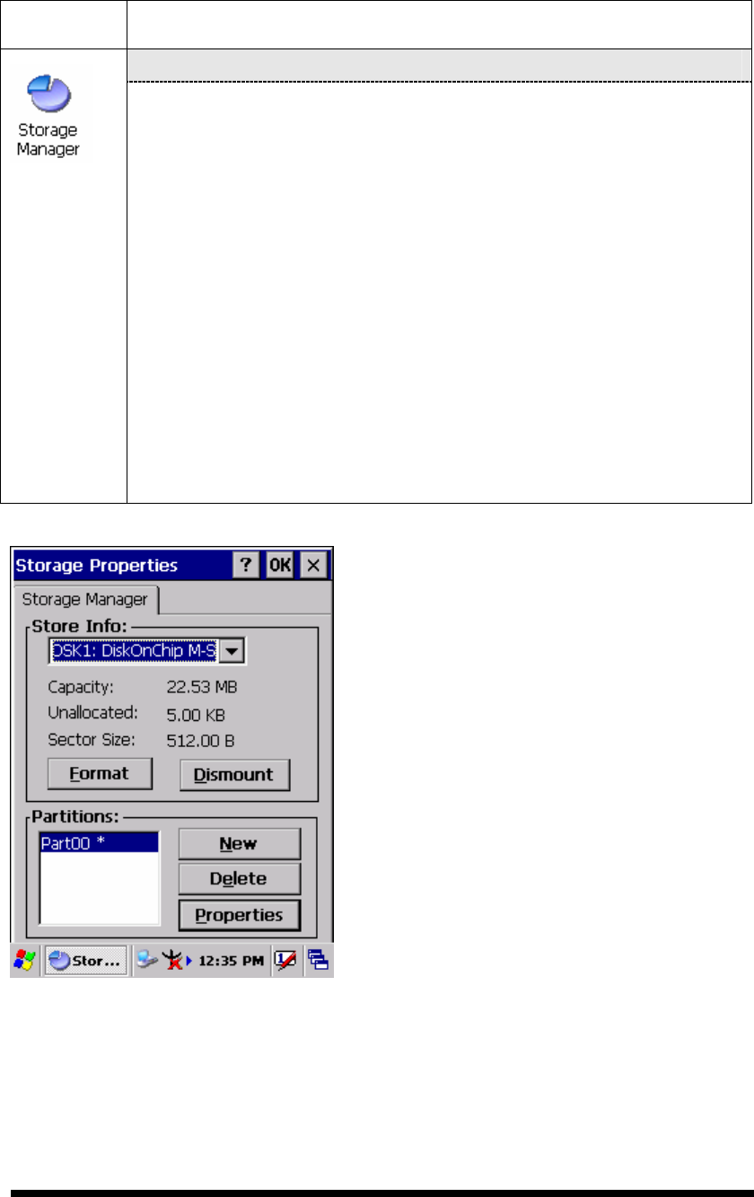
3.2.19 Storage Manager
Table 3-41 Storage Manager
ICON
ITEM & FUNCTION
“Storage Manager” Tab : (Figure 3-83)
To change Storage properties control panel default settings:
Insert. Compact Flash(CF) or Secure digital (SD) storage card into
the unit.
Select Start > Settings > Control Panel > Storage Properties
From the “Storage Info” pull-down list, select the desired
storage device.
You can also format, dismount, and create partitions on storage
devices using this control panel.
To save and exit the Storage Properties control panel, press
“OK” from the control bar, or press the <Enter> key on the
keypad.
Caution: Dismounting or formatting the DiskOnChip will
erase all files and program stored in Flash Memory
Figure 3-83 Storage Manager
3-54
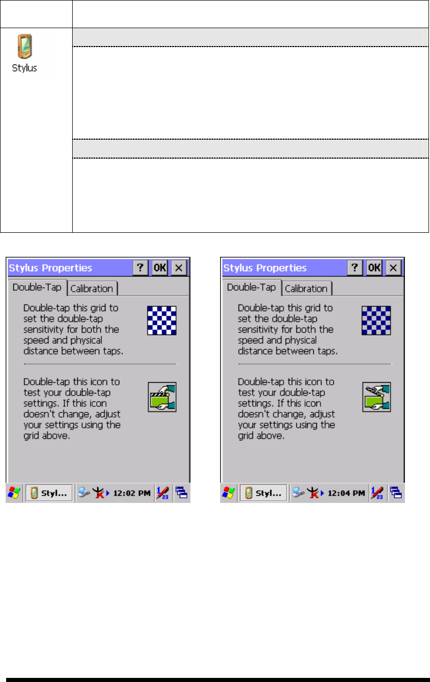
3.2.20 Stylus
Table 3-42 Stylus
ICON
ITEM & FUNCTION
“Double-Tap” Tab : (Figure 3-84,Figure 3-85)
Double-tap the checkerboard grip at a comfortable speed.
Double-tap clapboard to test your settings
The function is OK if the figures are changed from Figure 3-84
to Figure 3-85.
To tap “OK” to exit the Stylus Properties.
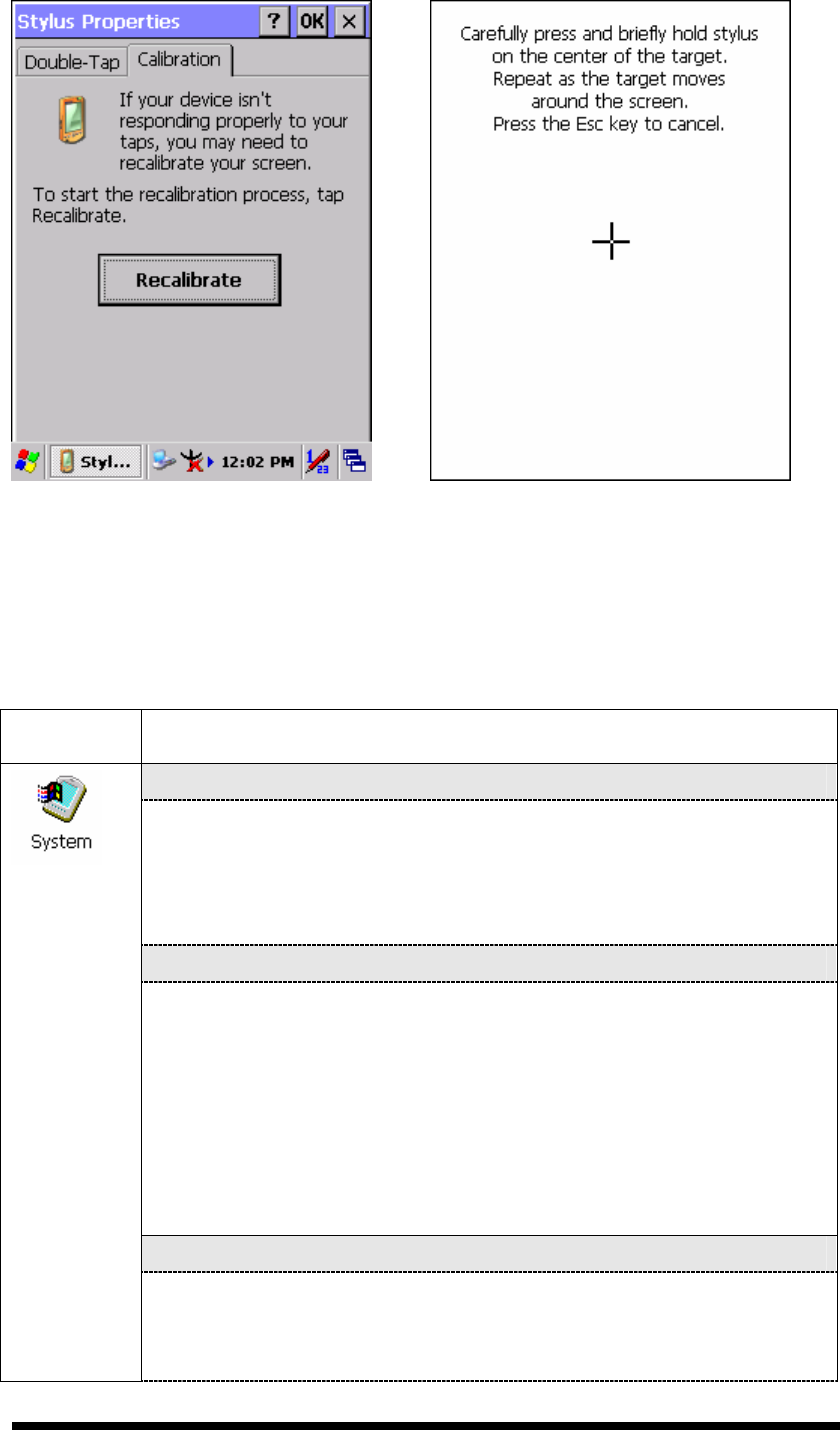
“
Calibration”: (Figure 3-86, Figure 3-87)
In the Welcome Wizard, you tapped a target with the stylus to set
the amount of pressure needed for the screen to respond to your
stylus taps.
Please also see 2.4.3 Calibration of the touch Screen
Figure 3-84 Stylus Properties Figure 3-85 Stylus Properties
3-55
Figure 3-86 Stylus Properties Figure 3-87 Stylus Properties
3.2.21 System
Table 3-43 System
ICON
ITEM & FUNCTION
“General” Tab : (Figure 3-88)
To show:
Firmware information
Information about Processor type, Memory size, Expansion
card
“
Memory”: (Figure 3-89)
Move the slider to adjust memory allocation. Default storage
memory is normally is normally set to about 8MB with the
reminder assigned to Program memory.
Press the “OK” key on the Keypad.
Note: the difference is occupied by OS between the RAM size in
Information properties and total memory size of storage memory
and program memory
“Device Name” Tab : (Figure 3-90)
Your device uses this information to identify itself to other
computers.
The input panel will open to facilitate data entry.
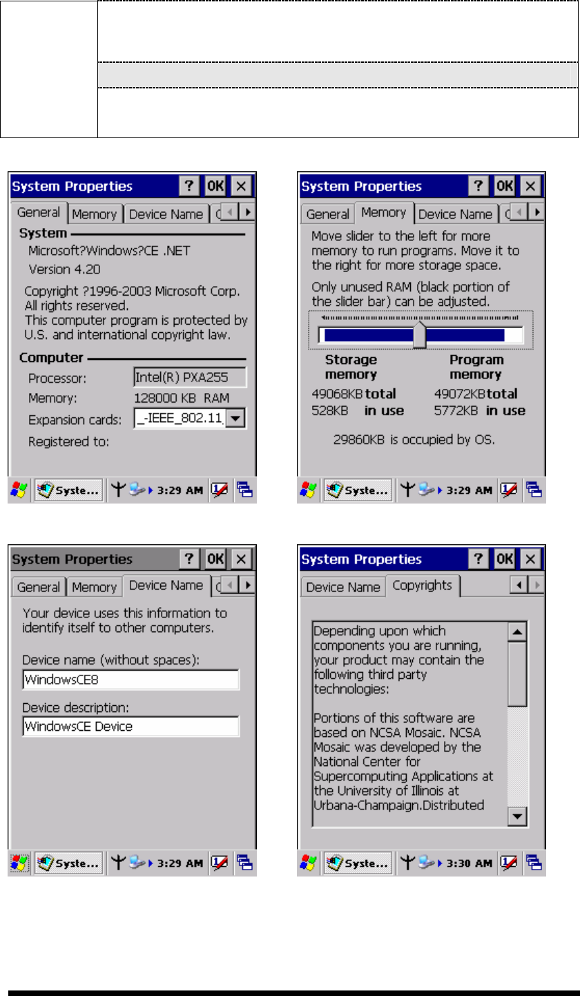
3-56
To close the Device Name, press the “OK” button, or press the
<Enter> key on keypad.
“
Copyrights” Tab: (Figure3-91)
Refer to this tab for specific copyright data. As a user, you are
responsible to read this statement.
Figure 3-88 System Properties Figure 3-89 System Properties
Figure 3-90 System Properties Figure 3-91 System Properties
3-57
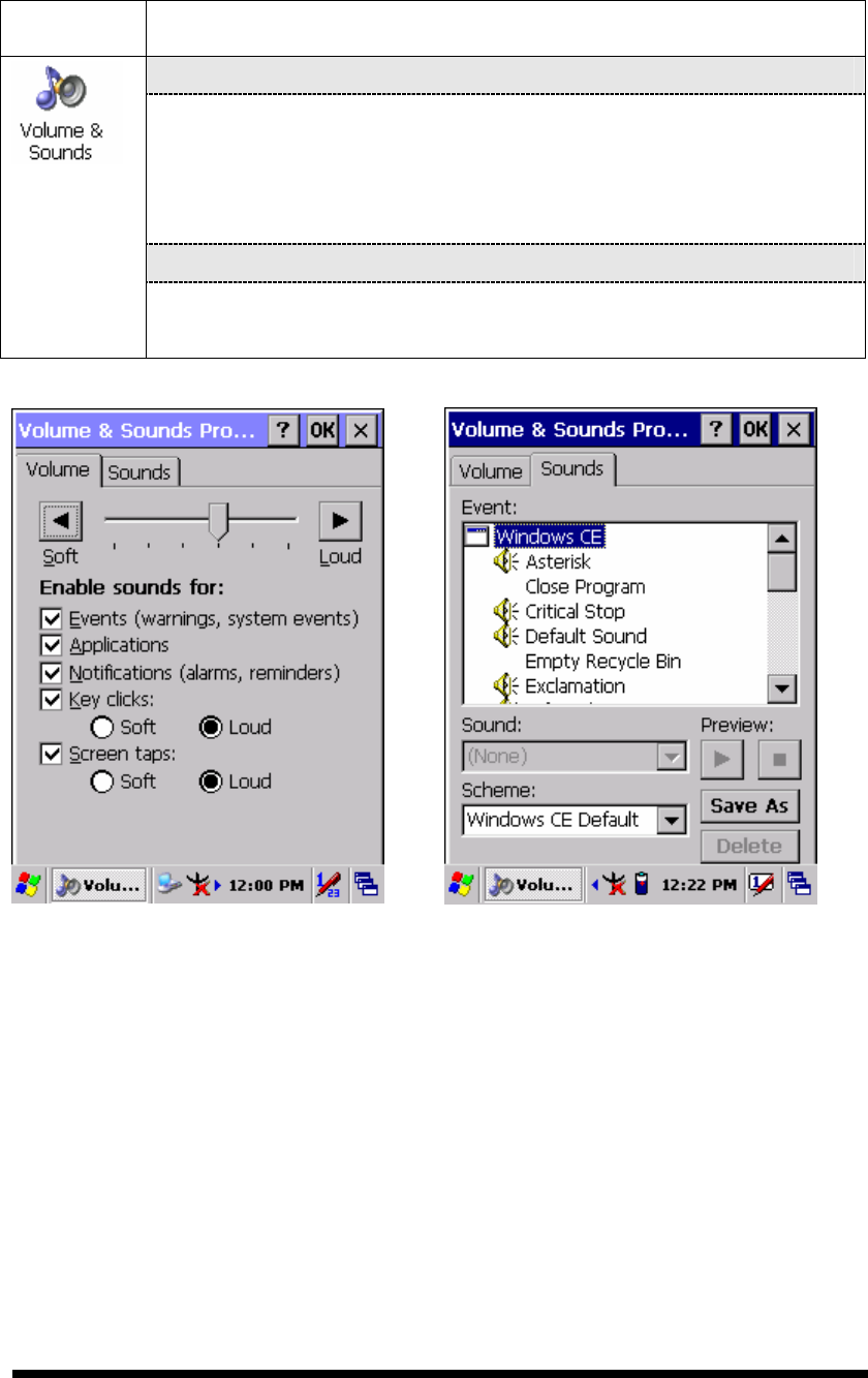
3.2.22 Volume & Sounds Properties
Table 3-44 Volume & Sound
ICON
ITEM & FUNCTION
“Volume” Tab : (Figure 3-92)
The factory default for Volume is the forth level. You can adjust
the volume to your environment and comfort.
Set the volume by adjusting the slider from Soft to Loud,
or press Right or Left edge of Navigation keys
“
Sounds ” Tab: (Figure3-93)
Enable the desired sounds for key clicks, screen taps,
notifications, and applications.
Figure 3-92 Volume & Sound Figure 3-93 Volume & Sound

3-58
3.3 Taskbar and Start Menu
Table 3-45 Taskbar and Start menu
ICON
ITEM & FUNCTION
“General” Tab :
In this tab, You can change the position of the Taskbar and Start
menu
Is always on top or not
Auto hide or not
Show Clock or not
“
Advanced ” Tab:
Taskbar and
Start Menu
Tap the “Clear” button to remove the contents of the Documents
Menu.
Enable “□
□□
□ Expand Control Panel”
””
” to list all icons of
Control Panel from top to bottom.

4-1
Chapter 4. Communication
4.1 Installing & Setting Up Microsoft ActiveSync
4.1.1 Installing Microsoft ActiveSync on the Host PC
Microsoft ActiveSync is a file transfer tool to synchronize the files on a PC with the
files on your PDT.
To install Microsoft ActiveSync, complete the following steps on the PC:
1. Go to the Microsoft Windows CE.NET website and download the latest current
version of ActiveSync:
http://www.microsoft.com/mobile/pockeypc/downloads/ .
2. Install the latest version of Microsoft ActiveSync on the host PC.
3. Open ActiveSync.
4. Select File > Communication Settings from AtiveSync’s menu bar.
5. Go to “Using ActiveSync” on page 4-1 to continue using ActiveSync.
4.1.2 Connecting PDT to Host PC
1. You can use either the USB/Serial (RS232) port of Single Dock or a USB/Serial
(RS232) cable to connect the PDT to the Host PC.
To use the dock, you must first insert the PDT into the slot, making sure that the
unit is firmly seated the dock.
To use the cable, connect the USB/Serial cable to the PDT.
2. Connect the USB/Serial dock or cable to the Host PC’s serial port or USB port.
3. Connect the dock or PDT to the power adapter and power source.
4.2 Using ActiveSync
Use ActiveSync to transfer and synchronize files between the PDT and the Host PC.
4.2.1 Setting up a Partnership
During the Microsoft ActiveSync installation, you were prompted to create a
partnership with your mobile device. When you set up a partnership, you select
synchronization and file conversation settings, which are contained in a file on your
desktop computer. This file enables your desktop computer to recognize your device.
4-2
Only devices that have a partnership with a desktop computer can synchronize
information between the two computers.
For more information on partnerships, please refer to your Microsoft ActiveSync
documentation or help file.
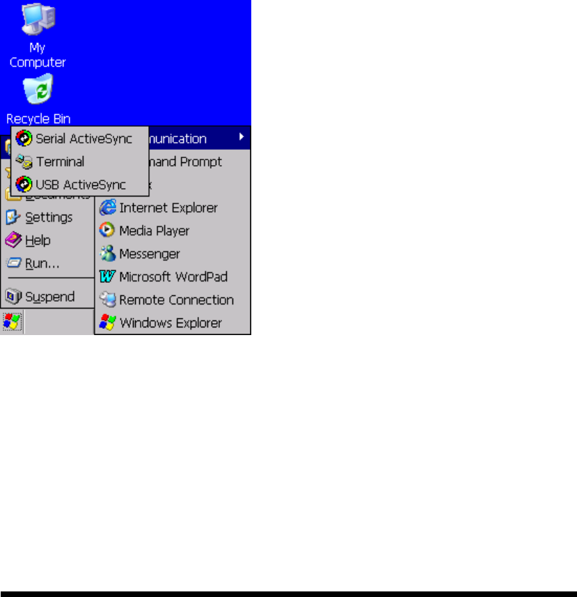
Transferring Files:
To transfer files, complete the following steps on the host PC:
Select Start> Programs >Communication > (Serial, or USB) Activesync.
Double-click on the selected ActiveSync icon
After you have established a connection with PDT, tap the “Explore” button at
the top of the ActiveSync window (or select Explore from the File menu).
Navigate to the target directory on your PDT and copy the desired file by using
the Copy/paste method or dragging and dropping the desired file(s) into the
folder.
Figure 4-1 Communication