Shin Chuan Computer SC800PDT-BW Portable Data Terminal User Manual Manual
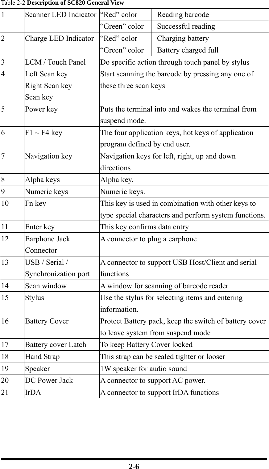
Shin Chuan Computer Co., Ltd. Portable Data Terminal Manual
UserManual.wiki
>
Shin Chuan Computer
>
SC800PDT BW User Manual
Manual
Navigation menu
Upload a User Manual
Namespaces
Wiki Guide
HTML
PDF
Info
Views
User Manual
Discussion / Help
Navigation
![1-5 - Electromagnetic compatibility and Radio Spectrum Matters (ERM); ElectroMagnetic Compatibility (EMC) standard for radio equipment and services; Part 1: Common technical requirements - EN 301 489-17 V1.2.1 (2002-08) - Electromagnetic compatibility and Radio spectrum Matters (ERM); ElectroMagnetic Compatibility (EMC) standard for radio equipment and services; Part 17: Specific conditions for 2,4 GHz wideband transmission systems and 5 GHz high performance RLAN equipment - EN 301 489-7 V1.2.1: (2002-08) ElectroMagnetic compatibility and Radio spectrum Matters (ERM); ElectroMagnetic Compatibility (EMC) standard for radio equipment ad services; Part 7: Specific conditions for mobile and portable radio and ancillary equipment of digital cellular radio telecommunications systems (GSM and DCS) This device is a 2.4 GHz wideband transmission system (transceiver), intended for use in all EU member states and EFTA countries, except in France and Italy where restrictive use applies. In Italy the end-user should apply for a license at the national spectrum authorities in order to obtain authorization to use the device for setting up outdoor radio links and/or for supplying public access to telecommunications and/or network services. This device may not be used for setting up outdoor radio links in France and in some areas the RF output power may be limited to 10 mW EIRP in the frequency range of 2454 – 2483.5 MHz. For detailed information the end-user should contact the national spectrum authority in France. 0560 Česky [Czech] [Jméno výrobce] tímto prohlašuje, že tento [typ zařízení] je ve shodě se základními požadavky a dalšími příslušnými ustanoveními směrnice 1999/5/ES. Dansk [Danish] Undertegnede [fabrikantens navn] erklærer herved, at følgende udstyr [udstyrets typebetegnelse] overholder de væsentlige krav og øvrige relevante krav i direktiv 1999/5/EF.](https://usermanual.wiki/Shin-Chuan-Computer/SC800PDT-BW/User-Guide-953942-Page-9.png)
![1-6 Deutsch [German] Hiermit erklärt [Name des Herstellers], dass sich das Gerät [Gerätetyp] in Übereinstimmung mit den grundlegenden Anforderungen und den übrigen einschlägigen Bestimmungen der Richtlinie 1999/5/EG befindet.Eesti [Estonian] Käesolevaga kinnitab [tootja nimi = name of manufacturer] seadme [seadme tüüp = type of equipment] vastavust direktiivi 1999/5/EÜ põhinõuetele ja nimetatud direktiivist tulenevatele teistele asjakohastele sätetele. English Hereby, [name of manufacturer], declares that this [type of equipment] is in compliance with the essential requirements and other relevant provisions of Directive 1999/5/EC. Español [Spanish] Por medio de la presente [nombre del fabricante] declara que el [clase de equipo] cumple con los requisitos esenciales y cualesquiera otras disposiciones aplicables o exigibles de la Directiva 1999/5/CE. Ελληνική [Greek] ΜΕ ΤΗΝ ΠΑΡΟΥΣΑ [name of manufacturer] ΔΗΛΩΝΕΙ ΟΤΙ [type of equipment] ΣΥΜΜΟΡΦΩΝΕΤΑΙ ΠΡΟΣ ΤΙΣ ΟΥΣΙΩΔΕΙΣ ΑΠΑΙΤΗΣΕΙΣ ΚΑΙ ΤΙΣ ΛΟΙΠΕΣ ΣΧΕΤΙΚΕΣ ΔΙΑΤΑΞΕΙΣ ΤΗΣ ΟΔΗΓΙΑΣ 1999/5/ΕΚ. Français [French] Par la présente [nom du fabricant] déclare que l'appareil [type d'appareil] est conforme aux exigences essentielles et aux autres dispositions pertinentes de la directive 1999/5/CE. Italiano [Italian] Con la presente [nome del costruttore] dichiara che questo [tipo di apparecchio] è conforme ai requisiti essenziali ed alle altre disposizioni pertinenti stabilite dalla direttiva 1999/5/CE. Latviski [Latvian] Ar šo [name of manufacturer / izgatavotāja nosaukums] deklarē, ka [type of equipment / iekārtas tips] atbilst Direktīvas 1999/5/EK būtiskajām prasībām un citiem ar to saistītajiem noteikumiem. Lietuvių [Lithuanian] Šiuo [manufacturer name] deklaruoja, kad šis [equipment type] atitinka esminius reikalavimus ir kitas 1999/5/EB Direktyvos nuostatas. Nederlands [Dutch] Hierbij verklaart [naam van de fabrikant] dat het toestel [type van toestel] in overeenstemming is met de essentiële eisen en de andere relevante bepalingen van richtlijn 1999/5/EG. Malti [Maltese] Hawnhekk, [isem tal-manifattur], jiddikjara li dan [il-mudel tal-prodott] jikkonforma mal-ħtiġijiet essenzjali u ma provvedimenti oħrajn relevanti li hemm fid-Dirrettiva 1999/5/EC. Magyar [Hungarian] Alulírott, [gyártó neve] nyilatkozom, hogy a [... típus] megfelel a vonatkozó alapvetõ követelményeknek és az 1999/5/EC irányelv egyéb](https://usermanual.wiki/Shin-Chuan-Computer/SC800PDT-BW/User-Guide-953942-Page-10.png)
![1-7 elõírásainak. Polski [Polish] Niniejszym [nazwa producenta] oświadcza, że [nazwa wyrobu] jest zgodny z zasadniczymi wymogami oraz pozostałymi stosownymi postanowieniami Dyrektywy 1999/5/EC. Português [Portuguese] [Nome do fabricante] declara que este [tipo de equipamento] está conforme com os requisitos essenciais e outras disposições da Directiva 1999/5/CE. Slovensko [Slovenian] [Ime proizvajalca] izjavlja, da je ta [tip opreme] v skladu z bistvenimi zahtevami in ostalimi relevantnimi določili direktive 1999/5/ES. Slovensky [Slovak] [Meno výrobcu] týmto vyhlasuje, že [typ zariadenia] spĺňa základné požiadavky a všetky príslušné ustanovenia Smernice 1999/5/ES. Suomi [Finnish] [Valmistaja = manufacturer] vakuuttaa täten että [type of equipment = laitteen tyyppimerkintä] tyyppinen laite on direktiivin 1999/5/EY oleellisten vaatimusten ja sitä koskevien direktiivin muiden ehtojen mukainen. Svenska [Swedish] Härmed intygar [företag] att denna [utrustningstyp] står I överensstämmelse med de väsentliga egenskapskrav och övriga relevanta bestämmelser som framgår av direktiv 1999/5/EG.](https://usermanual.wiki/Shin-Chuan-Computer/SC800PDT-BW/User-Guide-953942-Page-11.png)
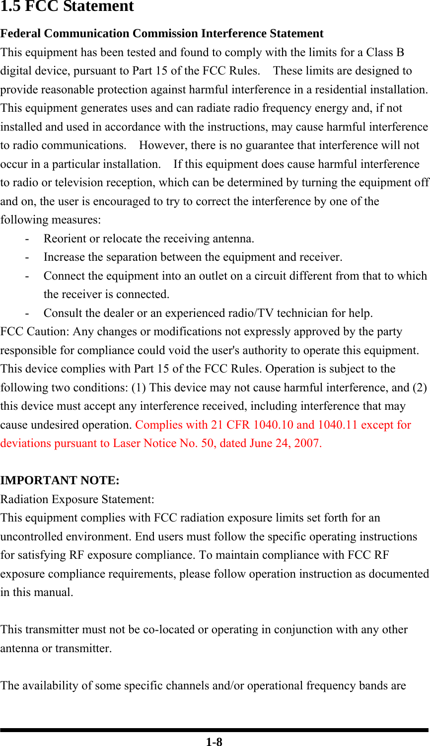

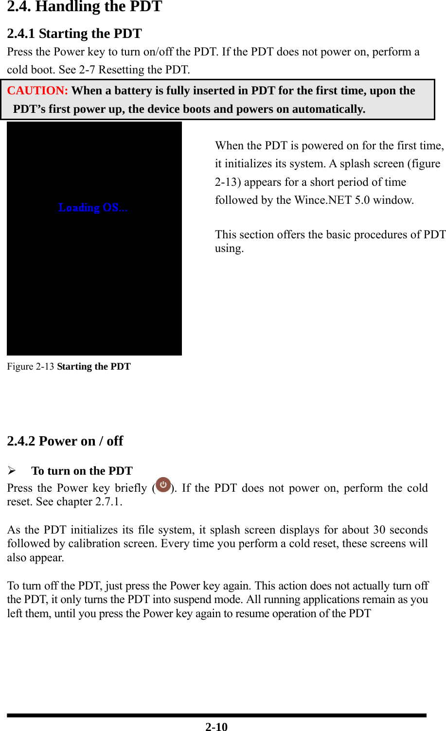
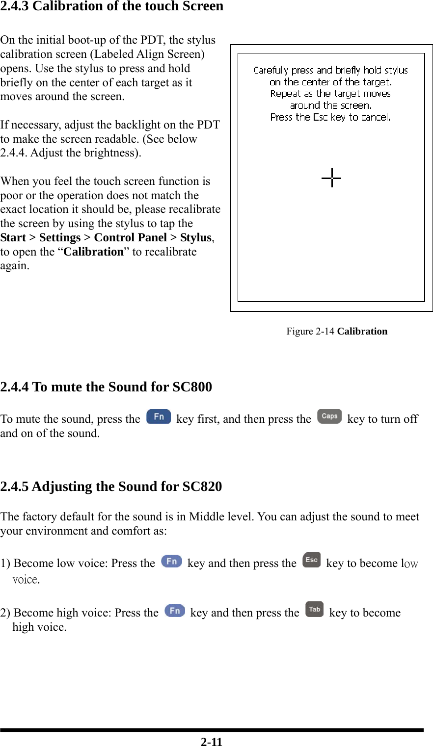
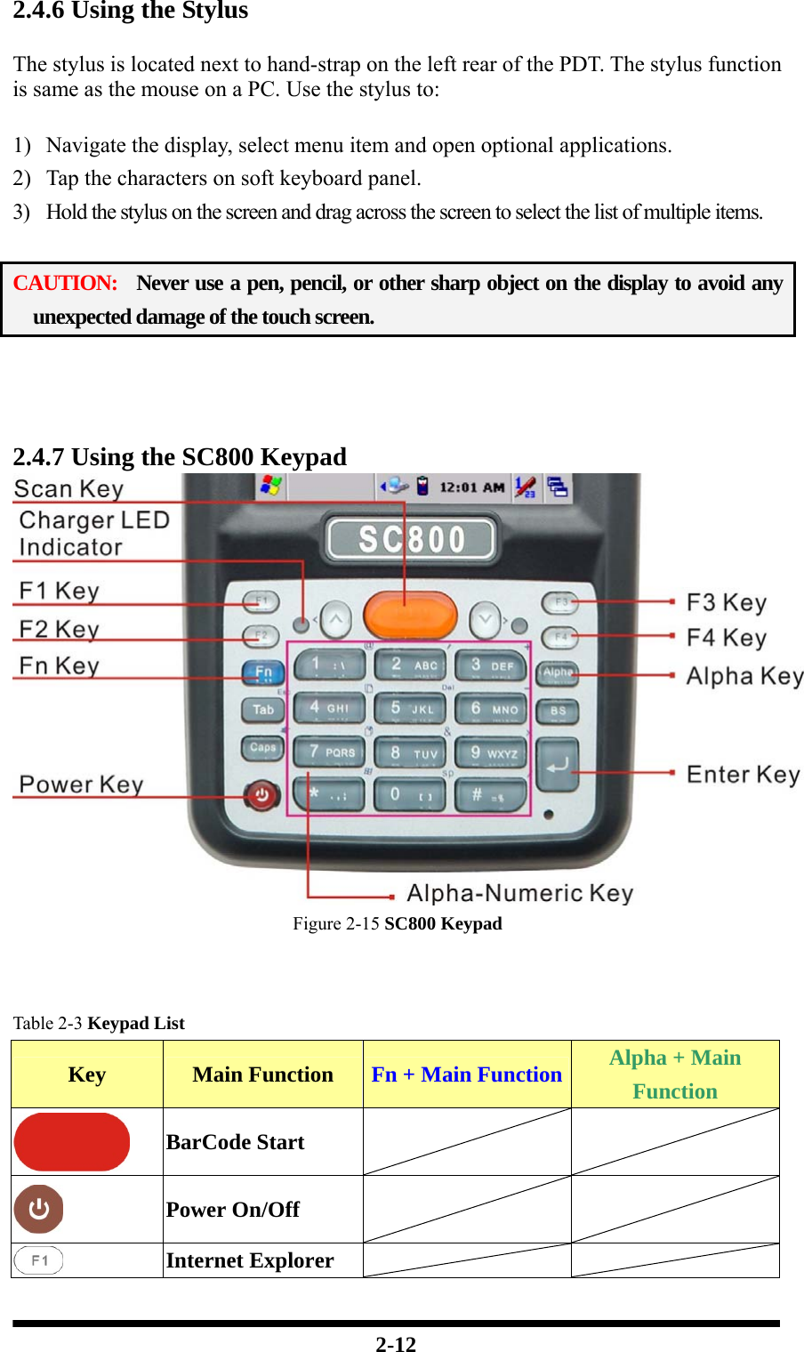
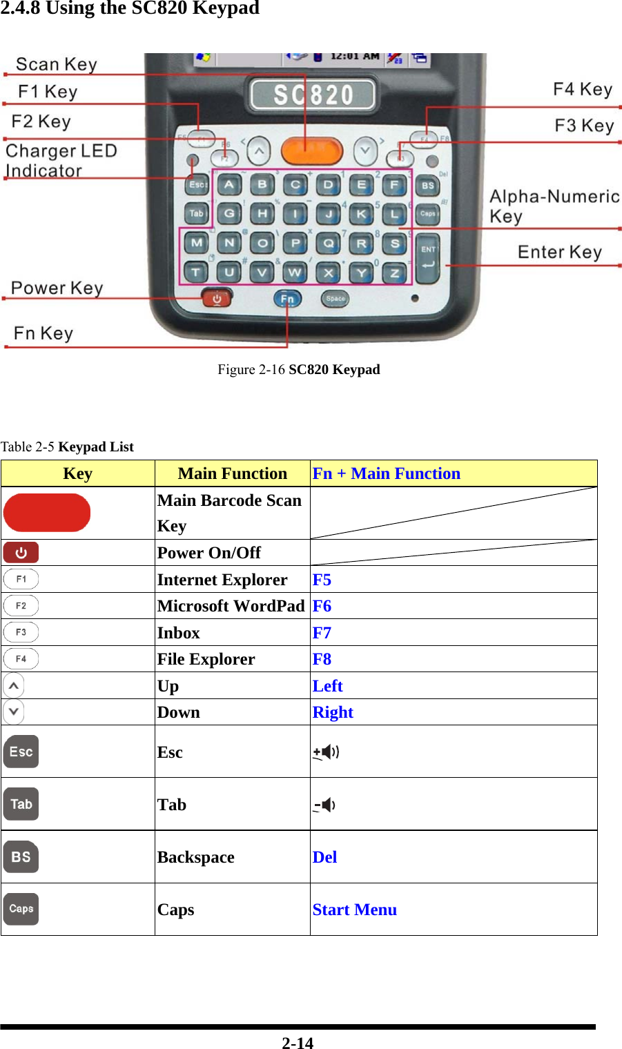
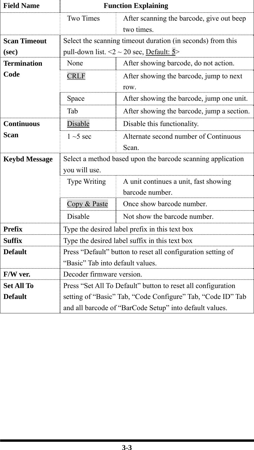
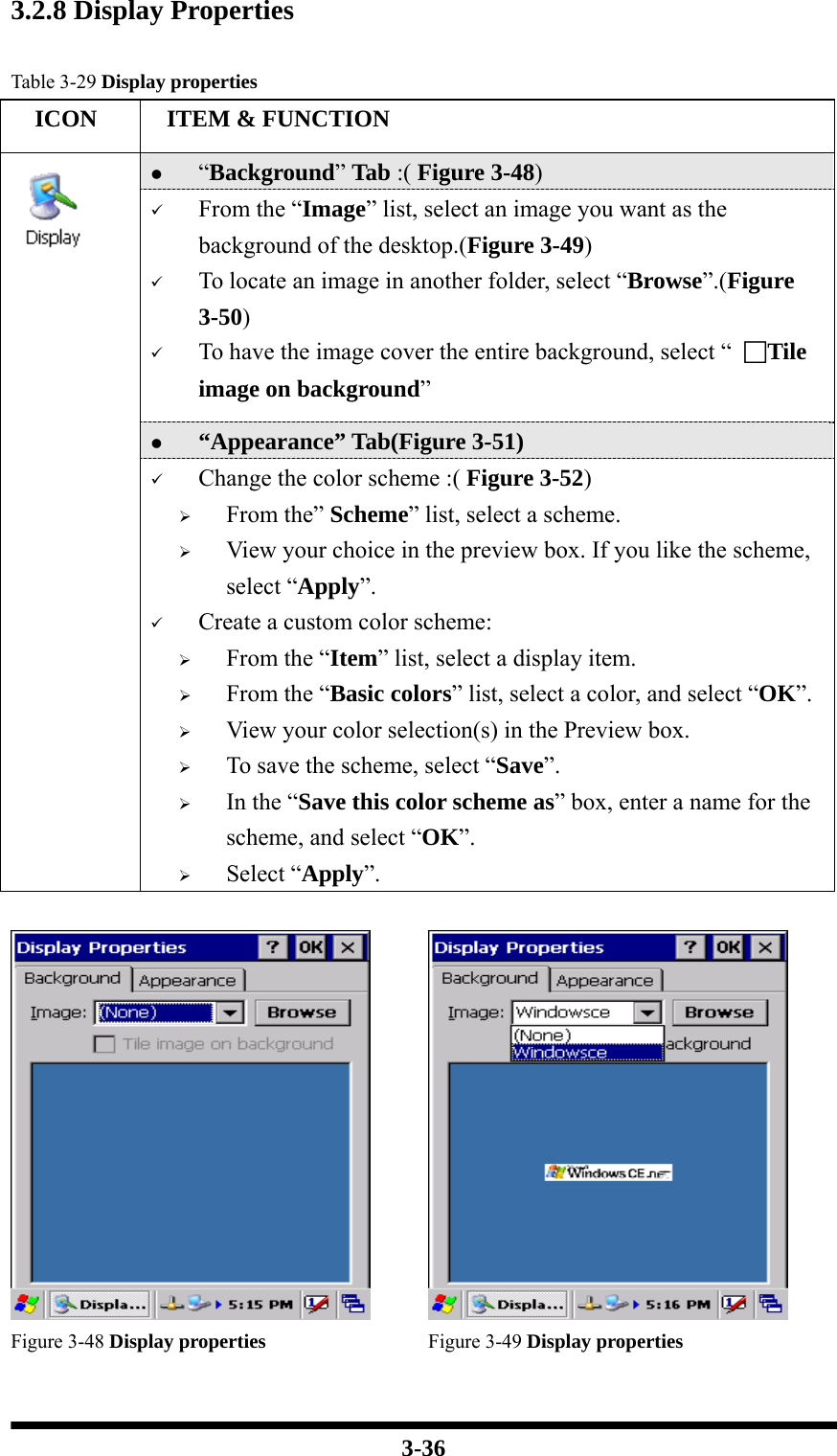
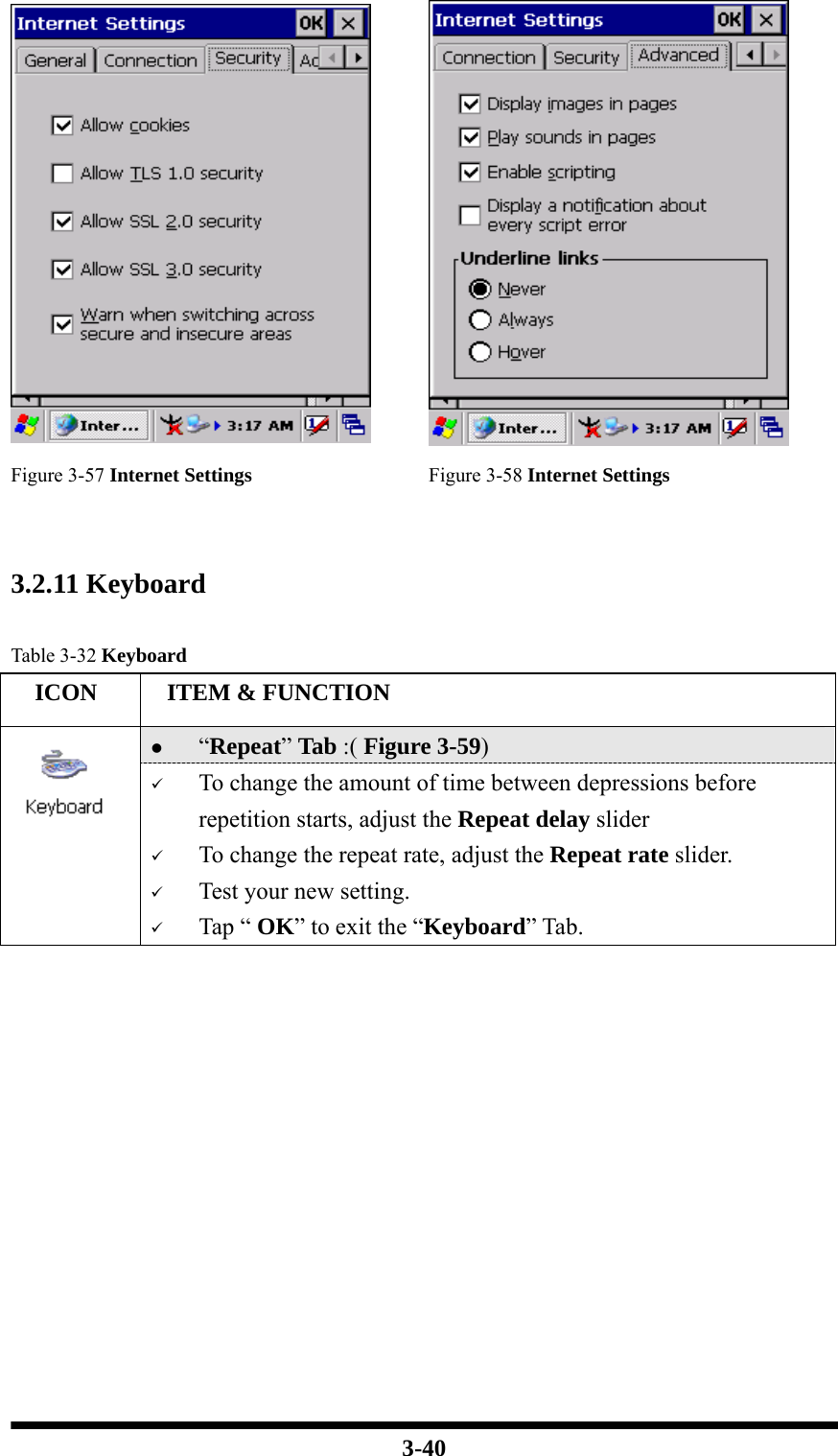
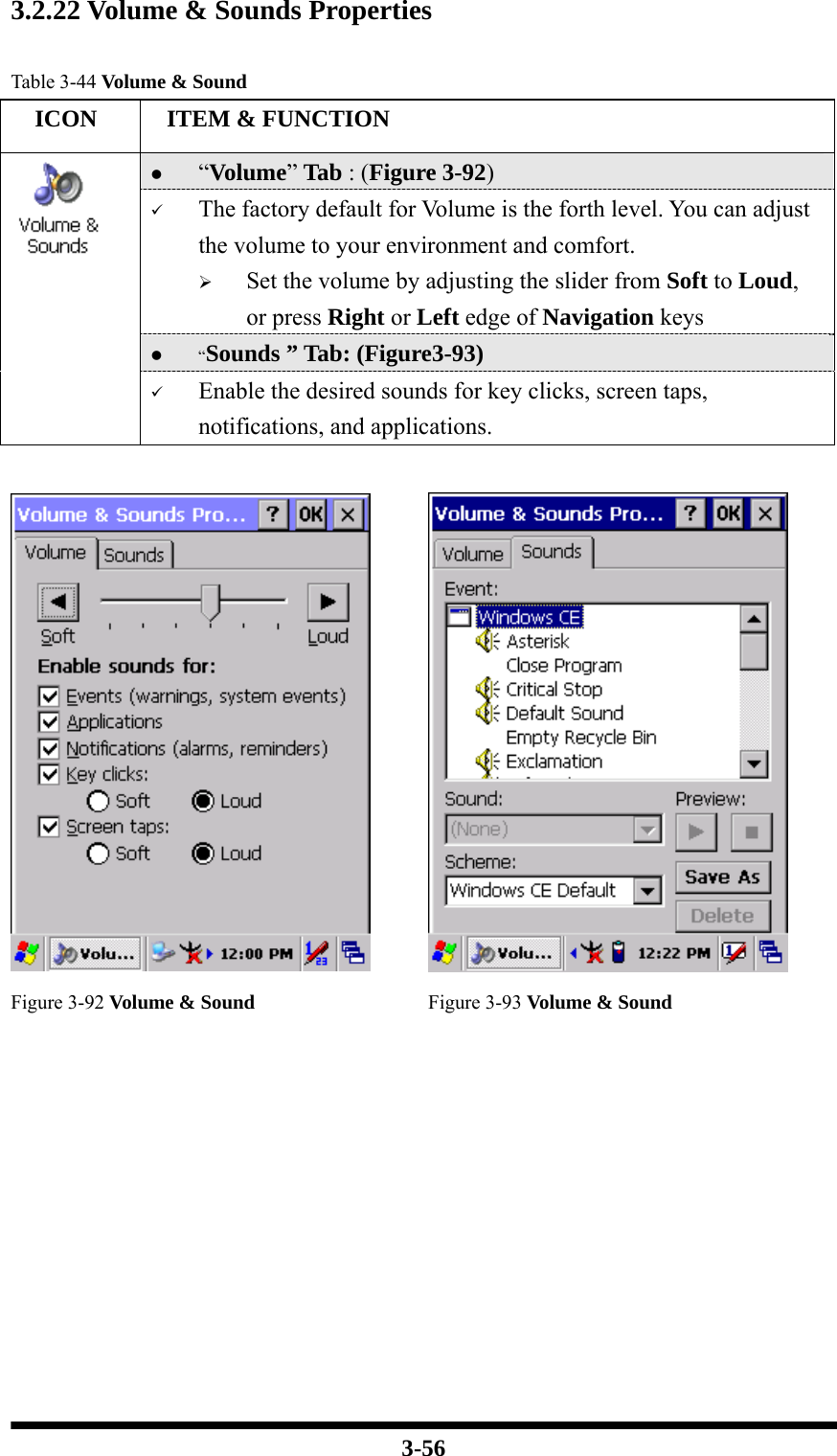
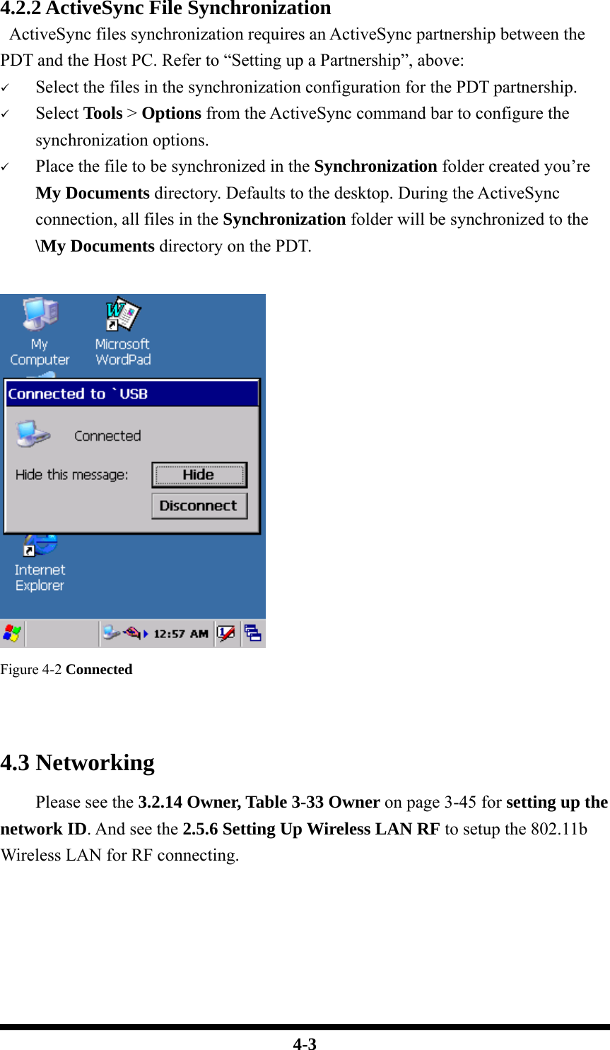
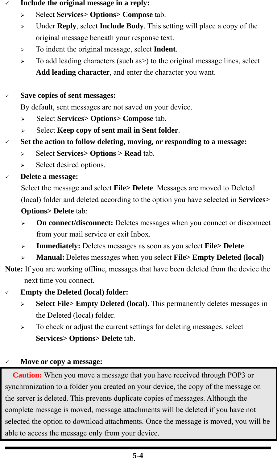
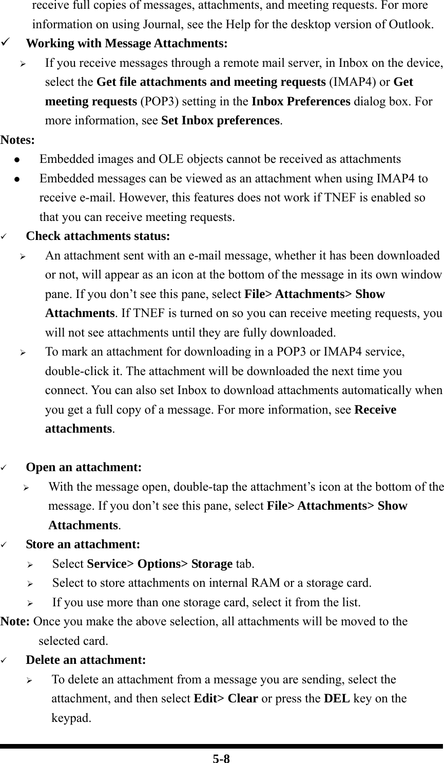
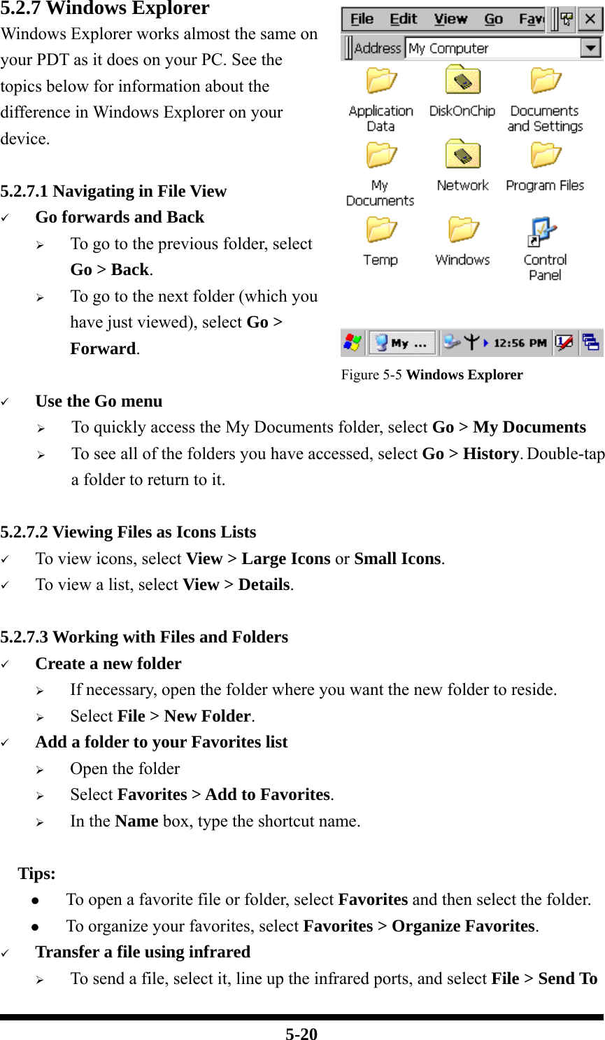
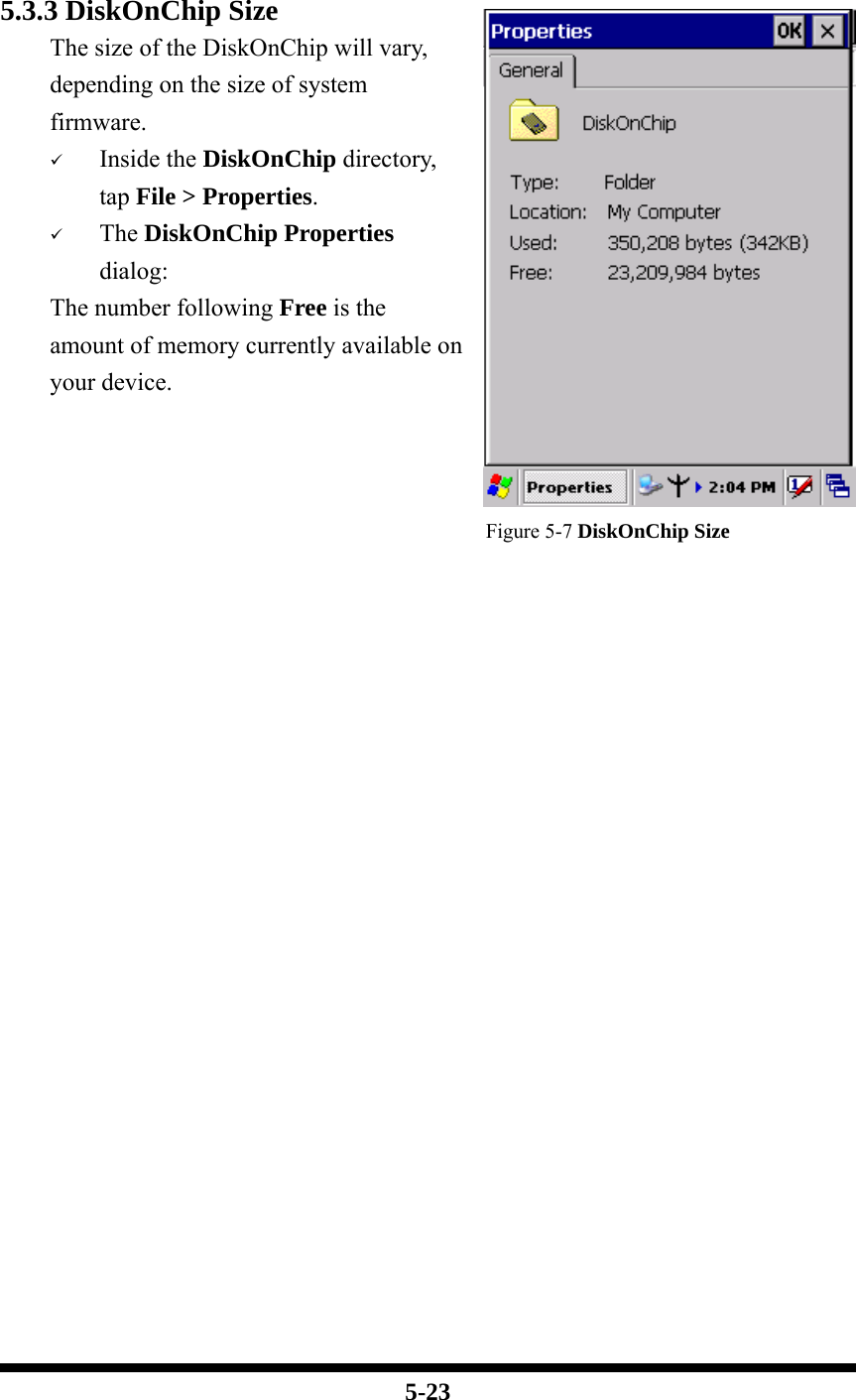
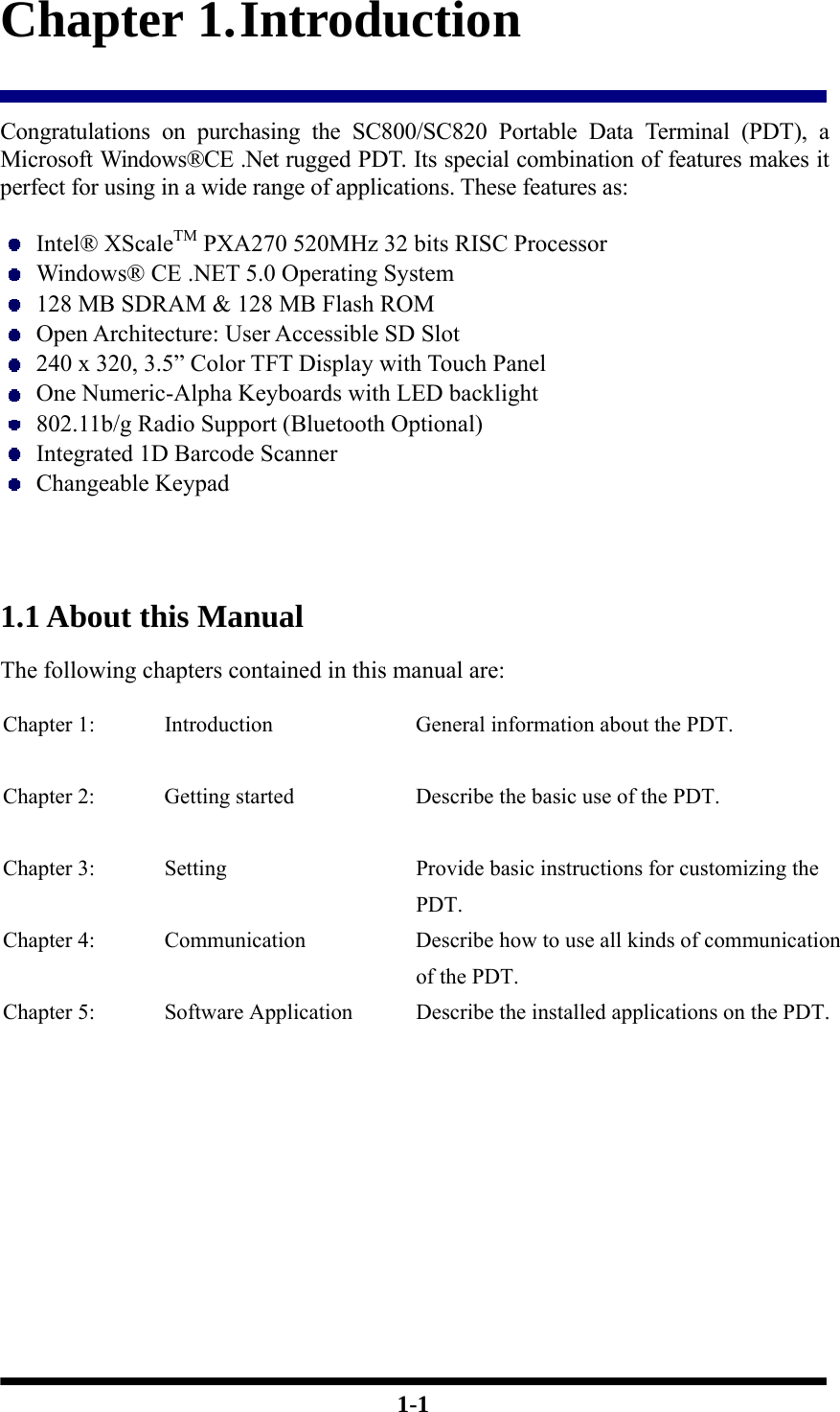
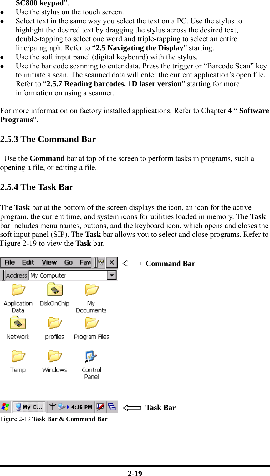
![2-18 2.5 Navigating the Display 2.5.1 Setting Time and Date In the Date/Time options, you can change the year, month, date, time, time zone, or select automatic adjust for Daylight Saving Time. To set or change the date and time: 1. Select Start > Settings > Control Panel > Date/Time 2. To change the year, select the year or open a numeric dial. Select the up arrow to increase the value; select the down arrow to decrease the value. Or you can type a new value in the field. 3. Select the month to open a pull-down list of months or press the arrow buttons to either side of the month to increase or decrease the month. Figure 2-18 Date/Time properties 4. To change the time, select the hour, minute, seconds, or AM/PM and select the up arrow to increase the value; select /tape the down arrow to decrease the value. Or you can type a new value in the field. 5. Select your correct time zone from the pull-down list. 6. To automatically adjust the clock for Daylight Saving Time, enable the checkbox at the bottom of the screen. 7. Select Apply to make save your changes [and make additional modifications] or select OK to exit the Date/Time settings. 2.5.2 Entering the Data To select and open programs, select Start > Programs from the task bar to open a list of available programs. Or if the program has a icon on the desktop, double-tap to open it. There are several ways to enter data on the PDT once in an application: z Use the keypad to enter alpha-numeric characters, Refer to “2.4.7 Using the](https://usermanual.wiki/Shin-Chuan-Computer/SC800PDT-BW/User-Guide-953942-Page-38.png)
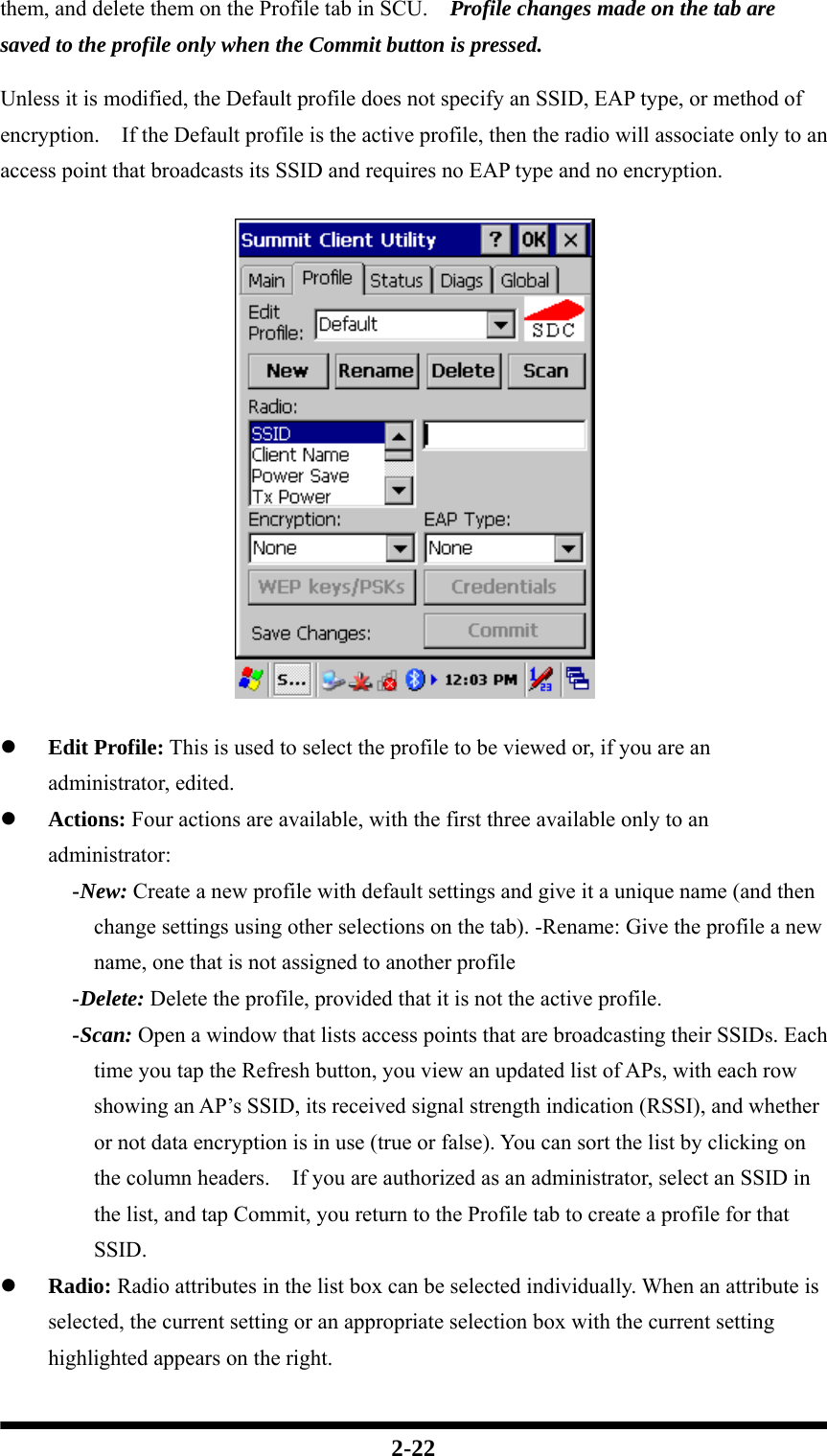
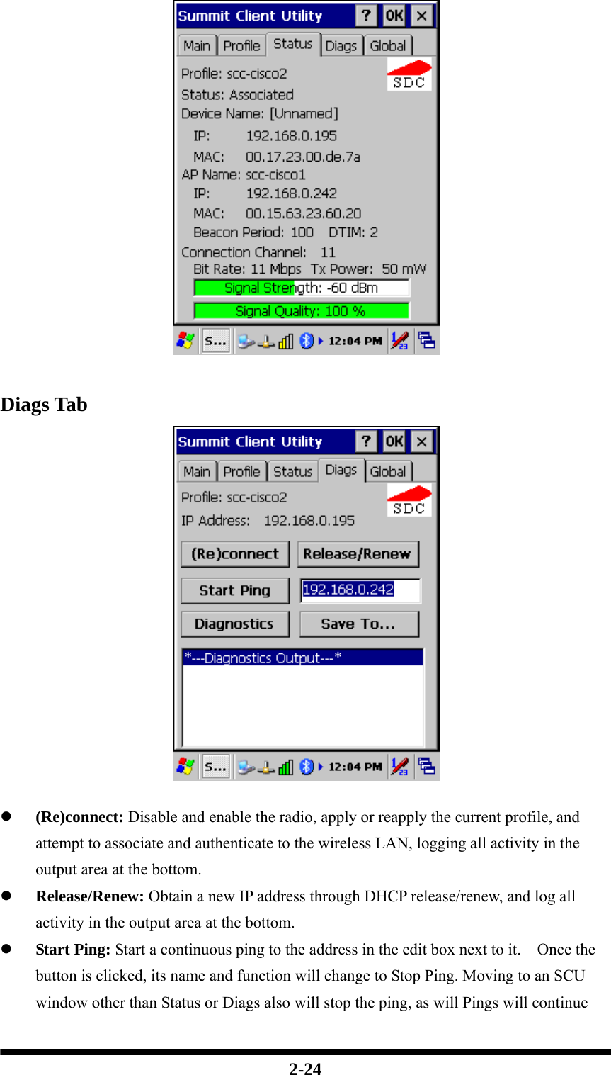
![2-23 z Security: Values for the two primary security attributes, EAP type and encryption type, are displayed in separate dropdown lists, with the current values highlighted. When you as an administrator select an EAP type, the Credentials button appears; when you tap it, a dialog box appears that enables you to define authentication credentials for that EAP type. When you as an administrator select an encryption type that requires the definition of WEP keys or a pre-shared key, the PSKs/WEP Keys button appears; when you tap it, a dialog box appears that enables you to define WEP keys or a PSK. z Commit: To ensure that changes to profile settings made on the tab are saved in the profile, you must tap the Commit button. To cause a Summit radio to connect to a typical business WLAN, you must select a profile that specifies the SSID, EAP type, and encryption type supported by the WLAN: z SSID: This is the name or identification of the WLAN. z EAP type: This is the protocol used to authenticate the device and its user if the WLAN uses the Enterprise version of Wi-Fi Protected Access (WPA) and WPA2. SCU supports five EAP types: PEAP with EAP-MSCHAP (PEAP-MSCHAP), PEAP with EAP-GTC (PEAP-GTC), EAP-TLS, LEAP, and EAP-FAST z Encryption: This specifies the type of key used to encrypt and decrypt transmitted data and how that key is specified or derived. Encryption options include: - WPA2 or WPA with dynamic keys (derived from the EAP authentication process) - WPA2 or WPA with pre-shared keys - Static WEP keys Consult the user’s guide for details on all profile settings, including security settings. Status Tab The Status tab provides status information on the radio. z Active profile z Radio’s status: Down (not recognized), Disabled, Not Associated, Associated, or [EAP type] Authenticated z Client info: Name, IP address, and MAC address z AP info: Name, IP address, MAC address, beacon period, and DTIM interval z Connection info: Channel, data rate, transmit power, signal strength, and signal quality](https://usermanual.wiki/Shin-Chuan-Computer/SC800PDT-BW/User-Guide-953942-Page-43.png)