Shin Heung Precision SAP-6600 POS SYSTEM User Manual
Shin Heung Precision Co., Ltd. POS SYSTEM
UserManual.wiki
>
Shin Heung Precision
>
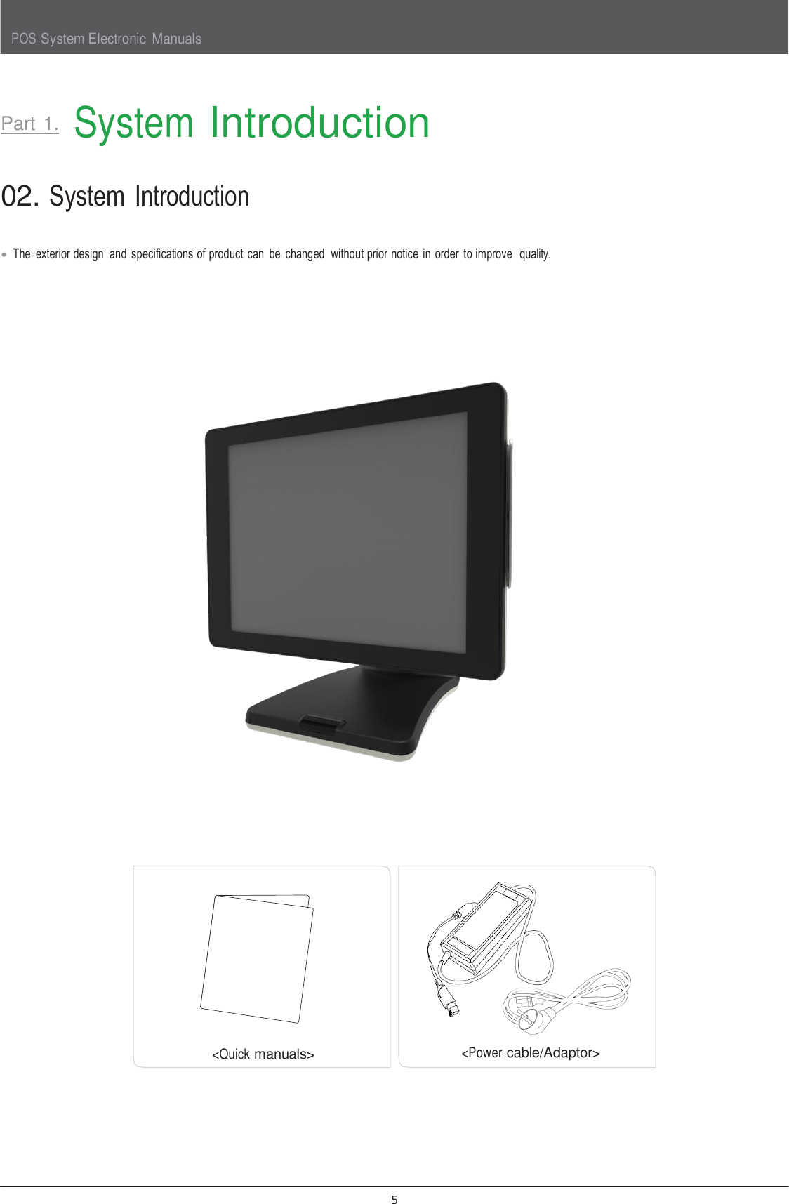
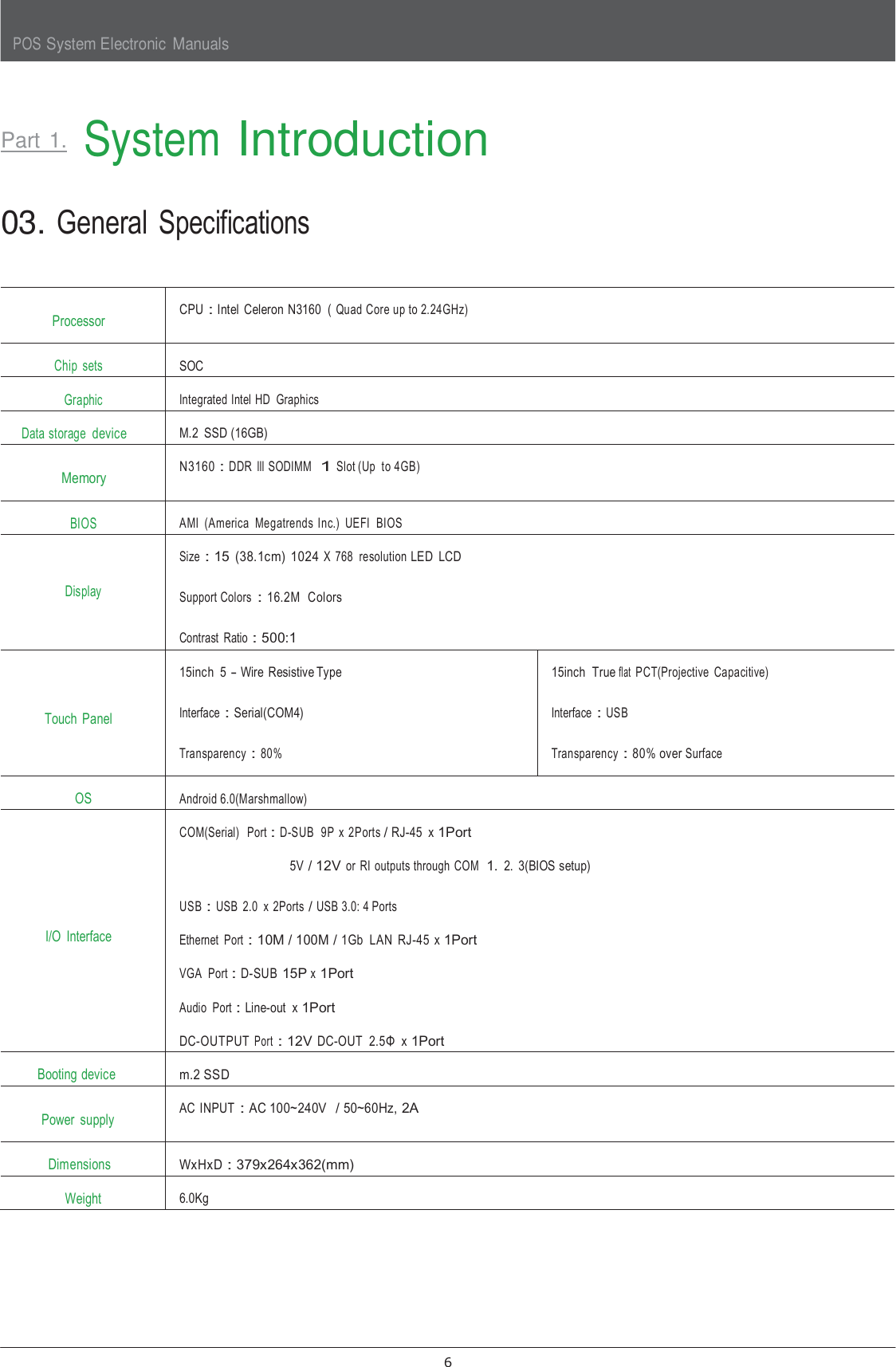
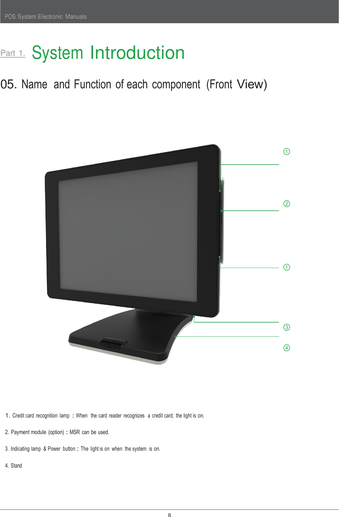
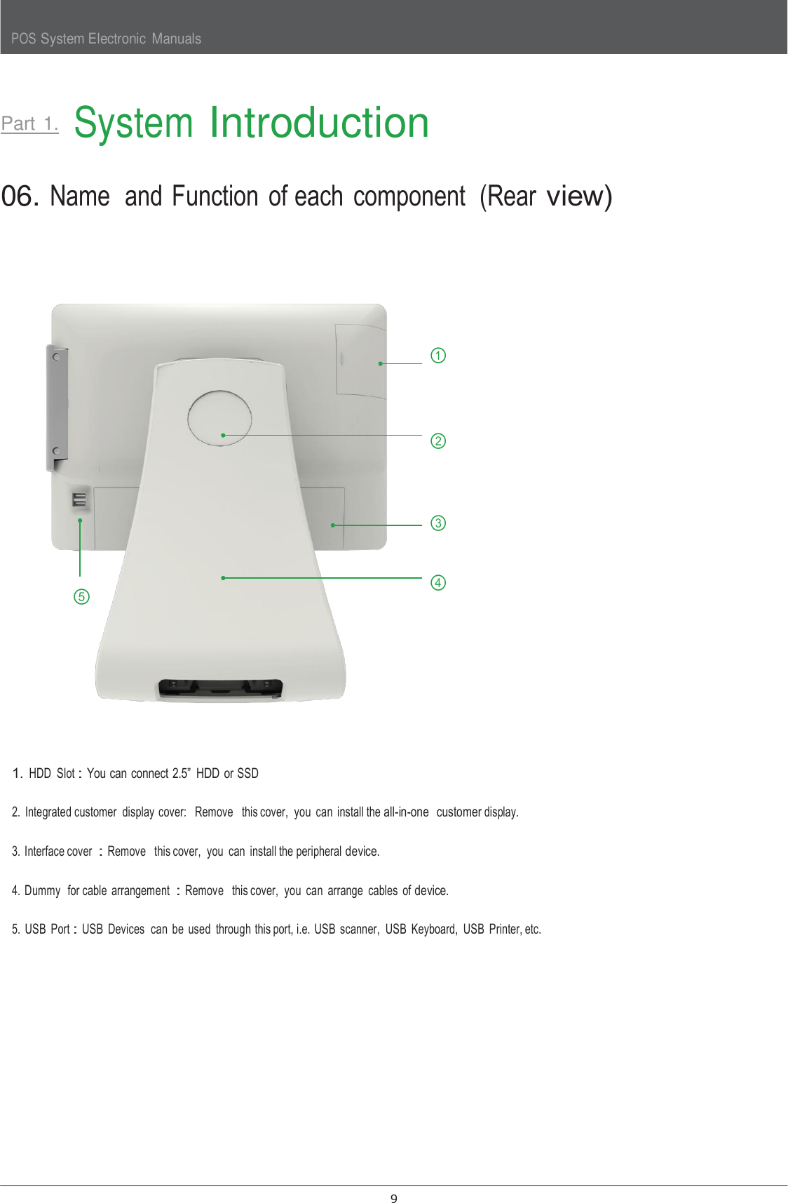
SAP 6600 User Manual
User Manual
Navigation menu
Upload a User Manual
Namespaces
Wiki Guide
HTML
PDF
Info
Views
User Manual
Discussion / Help
Navigation

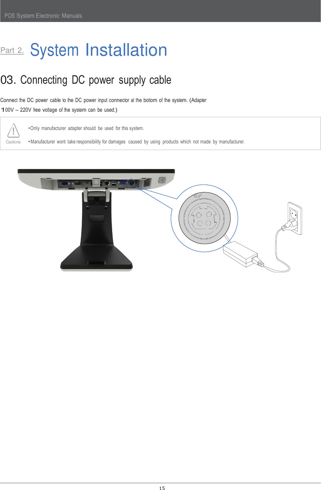
![POS System Electronic Manuals 4 The contents of HDD may be erased or the electronic components may be damaged. Carefully store or dispose of plastic packing material. It is dangerous if children put their head on it. Do not touch the power plug with a wet hand. You may get an electric shock. Do not touch modem, telephone line or exposed terminal during electrical storms. There may be electric shock or fire. Upgrade the system after shutting off the power of system and its peripheral device. The product may be damaged. [FCC Certification notice] This device complies with part 15 of the FCC Rules. Operation is subject to the following two conditions: (1) This device may not cause harmful interference, and (2) This device must accept any interference received, including interference that may cause undesired operation. This equipment has been tested and found to comply with the limits for a Class A digital device, pursuant to part 15 of the FCC Rules. These limits are designed to provide reasonable protection against harmful interference when the equipment is operated in a commercial environment. This equipment generates, uses, and can radiate radio frequency energy and, if not installed and used in accordance with the instruction manual, may cause harmful interference to radio communications. Operation of this equipment in a residential area is likely to cause harmful interference in which case the user will be required to correct the interference at his own expense. THE GRANTEE IS NOT RESPONSIBLE FOR ANY CHANGES OR MODIFICATIONS NOT EXPRESSLY APPROVED BY THE PARTY RESPONSIBLE FOR COMPLIANCE. SUCH MODIFICATIONS COULD VOID THE USER’S AUTHORITY TO OPERATE THE EQUIPMENT IMPORTANT NOTE : FCC RF Radiation Exposure Statement This equipment complies with FCC RF radiation exposure limits set forth for an uncontrolled environment. This equipment should be installed and operated with a minimum distance of 20 centimeters between the radiator and your body. This transmitter must not be co-located or operating in conjunction with any other antenna or transmitter.](https://usermanual.wiki/Shin-Heung-Precision/SAP-6600/User-Guide-3753506-Page-5.png)