Shin Heung Precision SAP-6600 POS SYSTEM User Manual
Shin Heung Precision Co., Ltd. POS SYSTEM
User Manual

POS
SYSTEM
Ele ctron i c
M
a n u a
l
s
Rev.1.00.160923.E
T
h
i
s
manual cons
i
s
t
s
o
f
s
y
s
t
e
m
i
n
t
r
o
d
uc
t
i
on,
s
y
s
t
e
m
i
ns
t
a
ll
a
t
i
on,
s
y
s
t
e
m
use, s
y
s
t
e
m
e
x
p
a
ns
i
on
and appendix
A/
B

POS
System Electronic Manuals
Contents
Part 1.
System Introduction
01.
Safety Notices Before Installation or
Use
02. System Introduction
03. General Specifications
04. Optional Specifications
05. Name and Function of each component (Front
View)
06. Name and Function of each component (Rear
view)
07. Name and Function of each component
(I/O)
Part 2.
System Installation
01.
Checking the Location for Installation
02. Before Connecting Peripherals
•
Interface
cover remove
•
Cable arrange
cover remove
03. Connecting DC power supply cable
Part 3.
System Utilization & Settings
01.
Resistive Normal touch
02. Wi-Fi
03. Ethernet
04. Bluetooth

POS
System Electronic Manuals
3
Part 1.
System
Introduction
01.
Safety Notices Before Installation or
Use
Read these cautions to avoid damage or injury.
Keep rated voltage.
The product can be damaged or burned by overvoltage.
Do not use damaged
components.
The product may be damaged unless
it
is repaired at service
cen
ter.
Install the product in a clean and dry place.
The product may not work properly in moist or dusty
environments.
Always copy important files.
Always copy important files because data loss cannot be guaranteed by
manufacturer.
Turn off the system and Remove the power cable before the product is
removed.
You may get an electric
shock.
Do not use loose or damaged power cables.
There may be electric shock or fire.
Always connect power cable to a grounded 3-wire
outlet.
It prevents electric shock from electrical short.
Install the product at a place with good
ventilation.
The product may be transformed or burned by overheating
if air vent is
blocked.
Use power strips designed for computers.
There may be fire caused by
overvoltage.
Use the cleaner which is only for computer.
Do not use benzene, thinner and alcohol or the product may be d
amaged.
Keep the product away from heaters.
The product may be damaged, overheated or burned.
Turn on the system after turning on peripheral device. Turn off peripheral device after turn off the
system.
The product may be damaged.
Install the product in a safe, stable
place.
The product may be damaged or you may get injured
if the
produc
t
is
dropped.
Keep the product away from magnetic materials.

POS
System Electronic Manuals
4
The contents of HDD may be erased or the electronic components may be damaged.
Carefully store or dispose of plastic packing
material.
It
is dangerous
if children put their head on
it.
Do not touch the power plug with a wet hand.
You may get an electric
shock.
Do not touch modem, telephone line or exposed terminal during electrical storms.
There may be electric shock or fire.
Upgrade the system after shutting off the power of system and its peripheral
device.
The product may be damaged.
[FCC Certification notice]
This device complies with part 15 of the FCC Rules. Operation is subject to the following two conditions:
(1) This device may not cause harmful interference, and
(2) This device must accept any interference received, including interference that may cause undesired operation.
This equipment has been tested and found to comply with the limits for a Class A digital device, pursuant to part 15 of the FCC Rules.
These limits are designed to provide reasonable protection against harmful interference when the equipment is operated in a commercial
environment. This equipment generates, uses, and can radiate radio frequency energy and, if not installed and used in accordance with
the instruction manual, may cause harmful interference to radio communications. Operation of this equipment in a residential area is likely
to cause harmful interference in which case the user will be required to correct the interference at his own expense.
THE GRANTEE IS NOT RESPONSIBLE FOR ANY CHANGES OR MODIFICATIONS NOT EXPRESSLY APPROVED BY THE PARTY
RESPONSIBLE FOR COMPLIANCE. SUCH MODIFICATIONS COULD VOID THE USER’S AUTHORITY TO OPERATE THE
EQUIPMENT
IMPORTANT NOTE : FCC RF Radiation Exposure Statement
This equipment complies with FCC RF radiation exposure limits set forth for an uncontrolled environment.
This equipment should be installed and operated with a minimum distance of 20 centimeters between the radiator and your body. This
transmitter must not be co-located or operating in conjunction with any other antenna or transmitter.
POS
System Electronic Manuals
5
Part 1.
System
Introduction
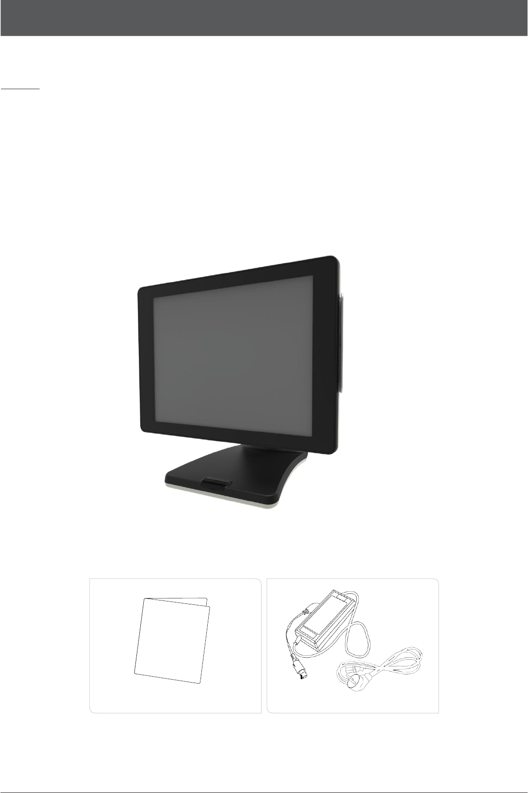
02.
System
Introduction
•
The exterior design and specifications of product can be changed without prior notice in order to improve quality.
<Quick
manuals>
<Power
cable/Adaptor>

POS
System Electronic Manuals
6
Part 1.
System
Introduction
03.
General
Specifications
Processor
CPU
:
Intel Celeron N3160 (
Quad Core up to 2.24GHz)
Chip sets
SOC
Graphic
Integrated Intel HD Graphics
Data storage
device
M.2 SSD (16GB)
Memory
N3160
:
DDR lll SODIMM
1
Slot (Up to 4GB)
N3160
:
DDR lll SODIMM
1
Slot (Up to 8GB)
BIOS
AMI (America Megatrends Inc.) UEFI BIOS
Display
Size
:
15
(38.1cm) 1024
X 768 resolution
LED LCD
Support Colors
:
16.2M Colors
Contrast Ratio
:
500:1
Backlight
:
250cd/m², 30,000 hours of product
life(LED Type)
Touch Panel
15inch 5
-
Wire Resistive Type
Interface
:
Serial(COM4)
Transparency
:
80%
Surface Hardness
:
3H
Hitting
Life
:
35 million times
15inch True
flat
PCT(Projective Capacitive)
Interface
:
USB
Transparency
:
80% over
Surface
Hardness
:
3H over
Hitting Life
:
100
million times
OS
Android 6.0(Marshmallow)
I/O Interface
COM(Serial) Port
:
D-SUB 9P x 2Ports
/
RJ-45 x
1Port
5V
/ 12V
or RI outputs through COM
1.
2. 3(BIOS setup)
USB
:
USB 2.0 x 2Ports
/
USB 3.0: 4 Ports
Ethernet Port
:
10M /
100M
/
1Gb LAN RJ-45 x
1Port
VGA Port
:
D-SUB
15P
x
1Port
Audio Port
:
Line-out x
1Port
DC-OUTPUT
Port
:
12V
DC-OUT 2.5Φ x
1Port
Booting device
m.2 SSD
Power supply
AC INPUT
:
AC 100~240V
/
50~60Hz,
2A
DC OUTPUT
:
12V / 5.0A(60W)
Dimensions
WⅹHⅹD
:
379ⅹ264ⅹ362(mm)
Weight
6.0Kg

POS
System Electronic Manuals
7
Part 1.
System
Introduction
04.
Optional Specifications
Magnetic Swipe
Reader(MSR)
Read Track
:
ISO track
1,
2, 3
Interface
:
Internal USB Performance
:
10~150
cm/sec
Head Reliability
:
500,000 times Error rate
:
Less than
0.5%
POS
System Electronic Manuals
8
Part 1.
System
Introduction
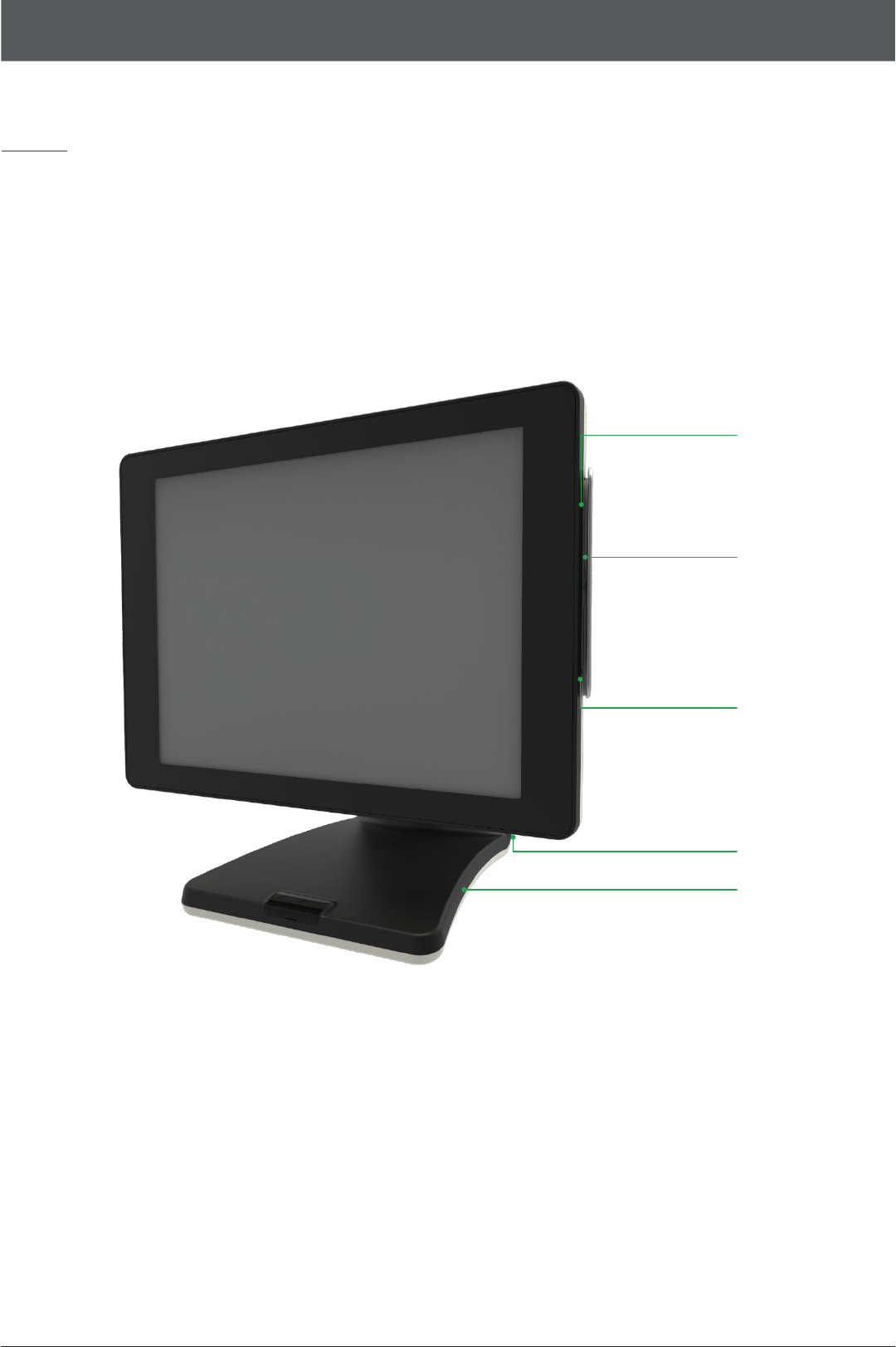
05.
Name and Function of each component (Front
View)
①
②
①
③
④
1.
Credit card recognition lamp
:
When the card reader recognizes a credit card, the light is
on.
2. Payment module (option)
:
MSR can be used.
3. Indicating lamp & Power button
:
The light is on when the system is
on.
4.
Stand
POS
System Electronic Manuals
9
Part 1.
System
Introduction
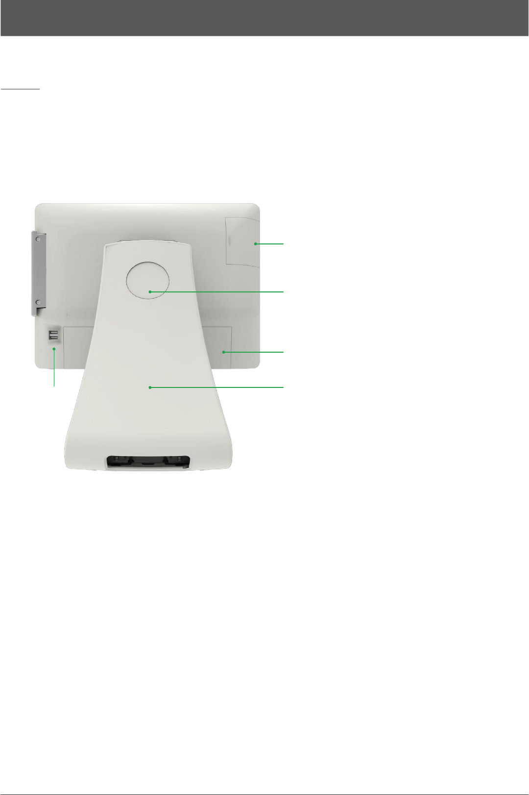
06.
Name and Function of each component (Rear
view)
①
②
③
④
⑤
1.
HDD Slot
:
You can connect 2.5” HDD or
SSD
2. Integrated customer display cover: Remove this cover, you can install the
all-in-one customer
display.
3. Interface cover
:
Remove this cover, you can install the peripheral
device.
4. Dummy for cable arrangement
:
Remove this cover, you can arrange cables of
device.
5. USB Port
:
USB Devices can be used through this port, i.e. USB scanner, USB Keyboard, USB Printer, etc.
POS
System Electronic Manuals
10
Part 1.
System
Introduction
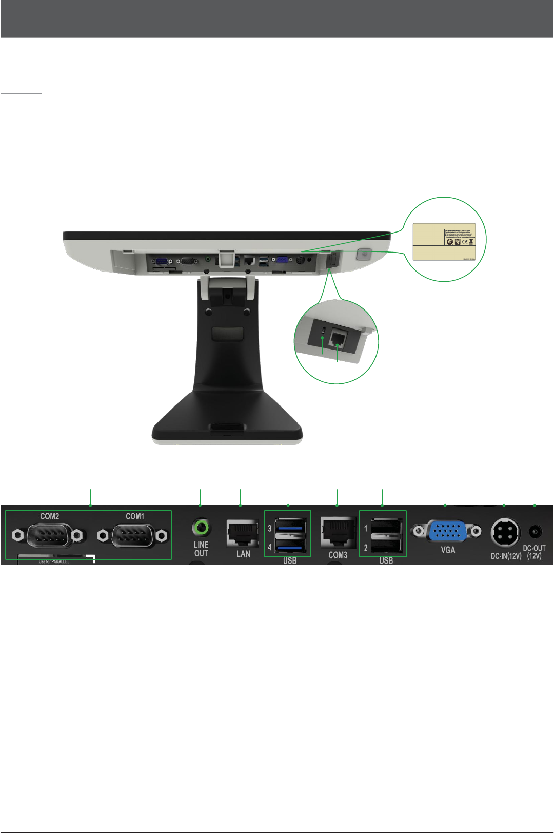
07.
Name and Function of each component
(I/O)
⑪
⑩
⑨
① ② ③
④-1
⑤ ④-2 ⑥ ⑦ ⑧
1.
D-SUB 9pin COM (Serial) port
:
You can connect serial devices such as barcode scanners, printers.
2. Audio port (Line-out)
:
You can connect the external speaker
s.
3. RJ-45 LAN (ETHERNET)
port
:
You can connect RJ45 cable for
100/1000
Mbps Ethernet connection.
4. USB 3.0 port
:
You can be used to connect devices such as the USB scanner, USB keyboard, USB printer.
5. RJ-45 8pin COM(Serial) Port
:
You can connect serial devices such as barcode scanners, printers.
6. D-SUB 15pin VGA port
:
You can connect the external
monitor.
7. 12V
DC Input (Input power connection)
:
Jack is connected to the adapter to supply power to the
system.
8. 2.5Φ
12V
DC Output(for Rear display)
:
System connected to an external DC power cable to the power that can be an output
ja
ck.
9.
RJ-11
6pin Cash Drawer port
:
You can connect the cash
drawe
r.

POS
System Electronic Manuals
11
10.
Setting switch of Cash drawer voltage (Option)
:
You can switch the power
(12V/24V)
for a cash
drawer.
11.
This is location of the label rating of the product.
POS
System Electronic Manuals
12
Part 2.
System
Installation
01.
Checking the Location for Installation
It is important to choose a safe and secure place to install the
terminal.
•
Choose a desk or table big and strong enough to support the weight of the system and peripherals.
•
Choose a flat, hard surface. Carpeted area can generate static electricity that can alter
memory or damage system components.
•
Make sure a system installed in a well-ventilated place and keep the space free around the
system.
•
Choose appropriate environmental conditions such as cool and dry places. Avoid humid and dusty places. Also avoid direct sunlight, rapidly changing
temperatures, or placing the system near heat
sources.
•
Select the appropriate voltage. Connect all the equipment into an isolated outlet to prevent static electricity and short circ
uit.
•
Where sufficient power outlets are available for printers and other peripheral
devices.
•
Do not install near electromagnetic and electrical devices, such as phones and electric moters,
that
can cause system damage.
•
The socket-outlet shall be installed near the equipment and shall be easily accessible.
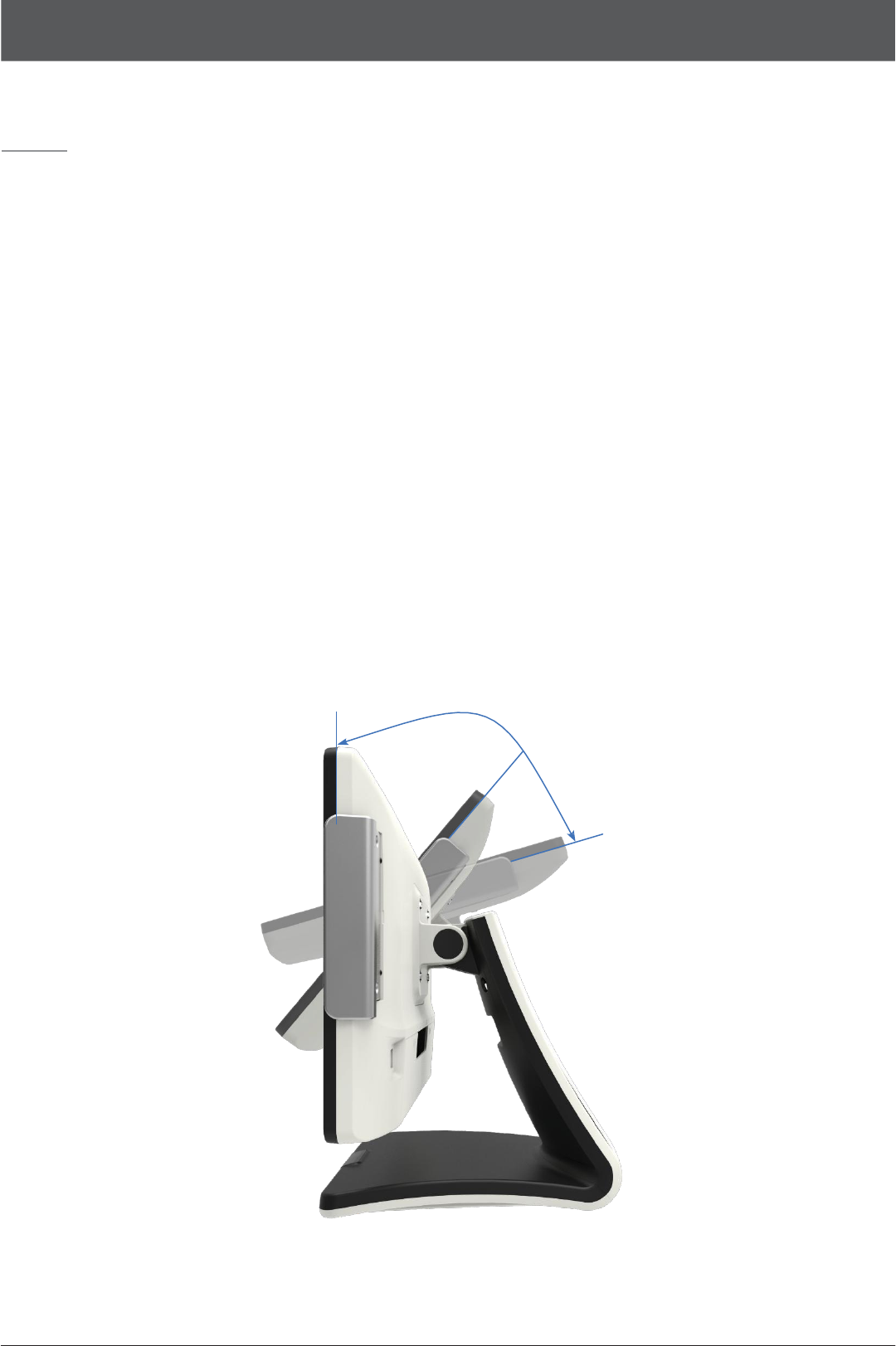
90˚
50˚
<STANDARD
ANGLE>
15˚

POS
System Electronic Manuals
13
Adjust the system depending on the condition and use
it
with the exact angle. Adjustable
angle shown in the figure.
•Use
the same battery for the product (motherboard) to prevent a risk of
explosion.
•Dispose
of used battery according to the separate instruction.
POS
System Electronic Manuals
14
Part 2.
System
Installation
02.
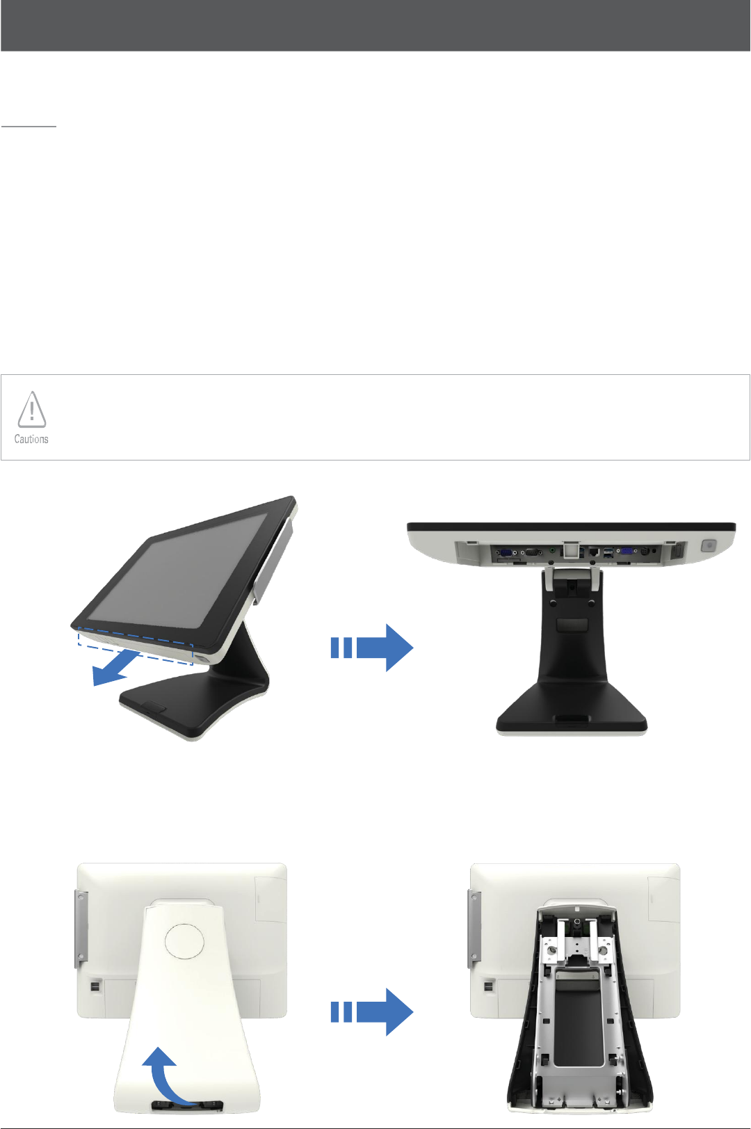
Before Connecting Peripherals
To connect peripherals first
remove
the ‘Interface cover’, which is in the bottom of the system, after that
remove the ‘Cable arrange
cover’
which is in the rear of the
system.
•
Interface cover
remove
1
.
As
it
shown
i
n
t
h
e
p
i
c
t
u
r
e
pull
t
h
e
‘
I
n
t
e
r
f
a
ce
co
v
e
r
’
i
n
t
h
e
d
i
r
ec
t
i
on
o
f
t
h
e
a
rr
o
w
.
•Turn
off the power of the body and connect peripherals.
•Connecting
peripherals to the corners parts of the system can cause hands injury. For your safety use the
gloves.
•
Cable arrange cover
remove
1
.
Remove t
h
e
‘
C
ab
l
e
arrange
co
v
e
r
’
i
n
t
h
e
d
i
r
ec
t
i
on
o
f
arrow shown
i
n
below p
i
c
t
u
r
e.
POS
System Electronic Manuals
15
Part 2.
System
Installation
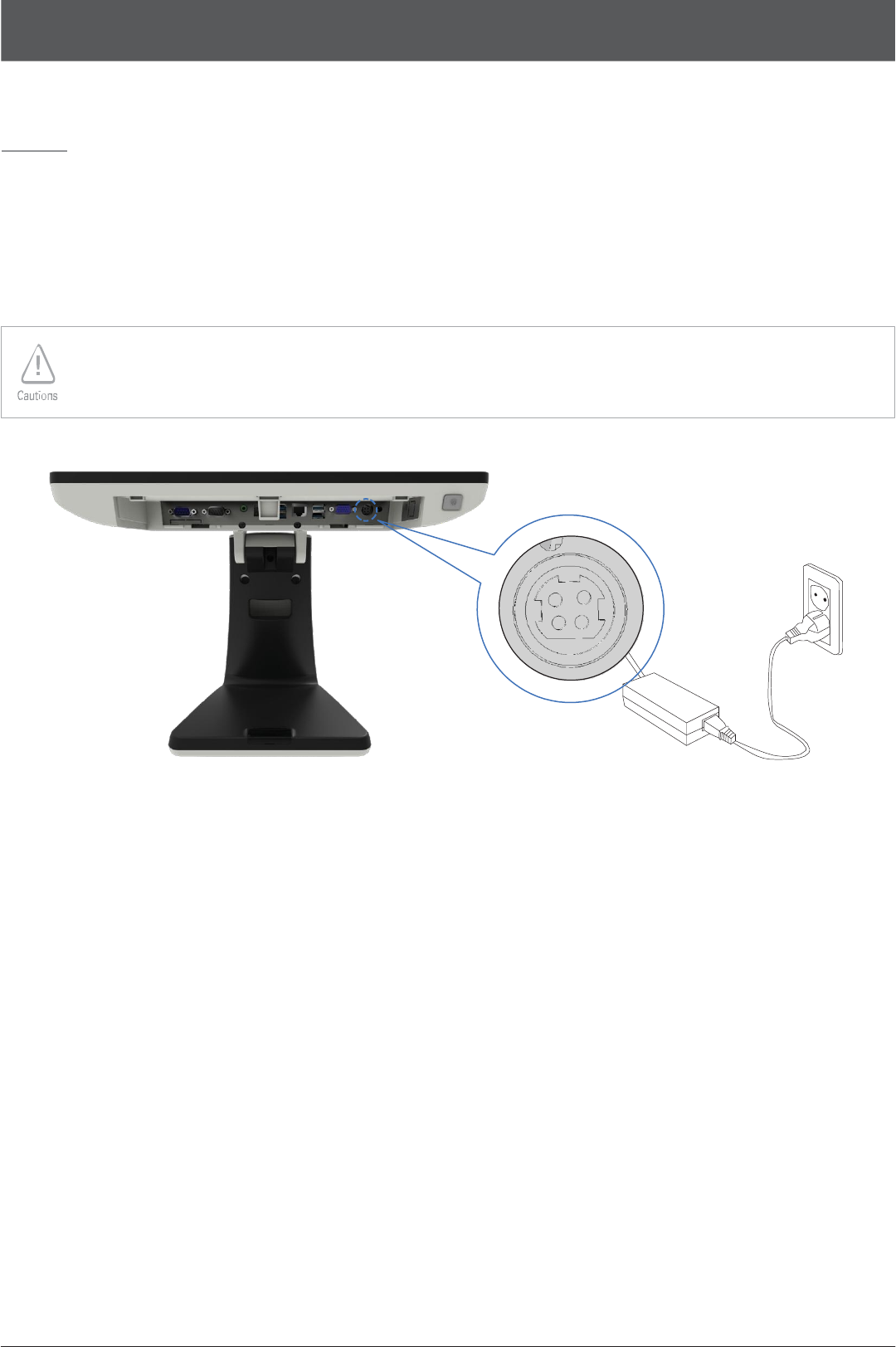
03.
Connecting DC power supply cable
C
onne
c
t
t
h
e
DC power cable
t
o
t
h
e
DC power
i
n
p
ut
c
onne
c
t
o
r
a
t
t
h
e
b
o
tt
o
m
o
f
t
h
e
sys
t
e
m.
(
A
d
a
p
t
e
r
1
00
V
–
220V
f
r
ee
v
o
l
t
ag
e
o
f
t
h
e
sys
t
e
m
can be us
e
d.
)
•Only
manufacturer adapter should be used for this system.
•
Manufacturer
wont take responsibility for damages caused by using products which not made by manufacturer.
POS
System Electronic Manuals
16
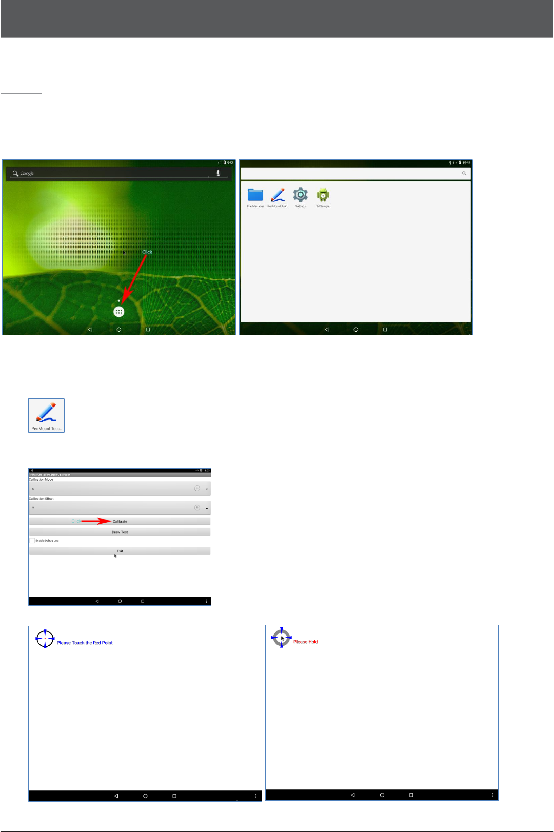
Part 3.
System Utilization
At First, please click the Menu Icon and follow as bellow sections in the list of Application.
01.
Resistive Normal
Touch
1. Click PenMount Touch Application
.
2. Select the options and Click the Calibrate. Recommend default
option as below.
3. Long press the Calibration Point as below.
POS
System Electronic Manuals
17
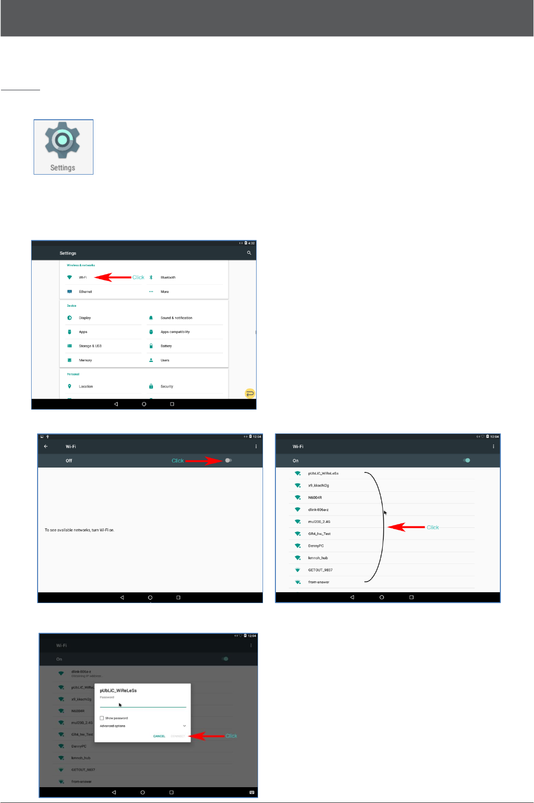
Part 3.
System
Settings
Click Settings Icon and follow belows.
02.
Wi-Fi
1. Click the Wi-Fi Menu
2. Turn on the Wi-Fi switch and click your router.
3. Input password and click the Connect.
POS
System Electronic Manuals
18
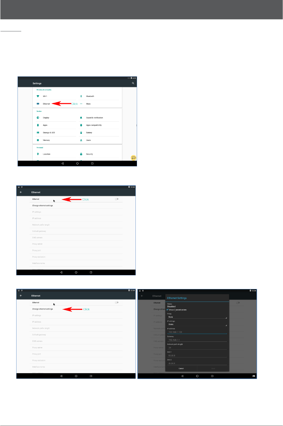
Part 3.
System Settings
03.
Ethernet
1. Click the Ethernet menu as bellow
2. Turn on the Switch.
3. You can change the Ethernet Settings as below.
POS
System Electronic Manuals
19
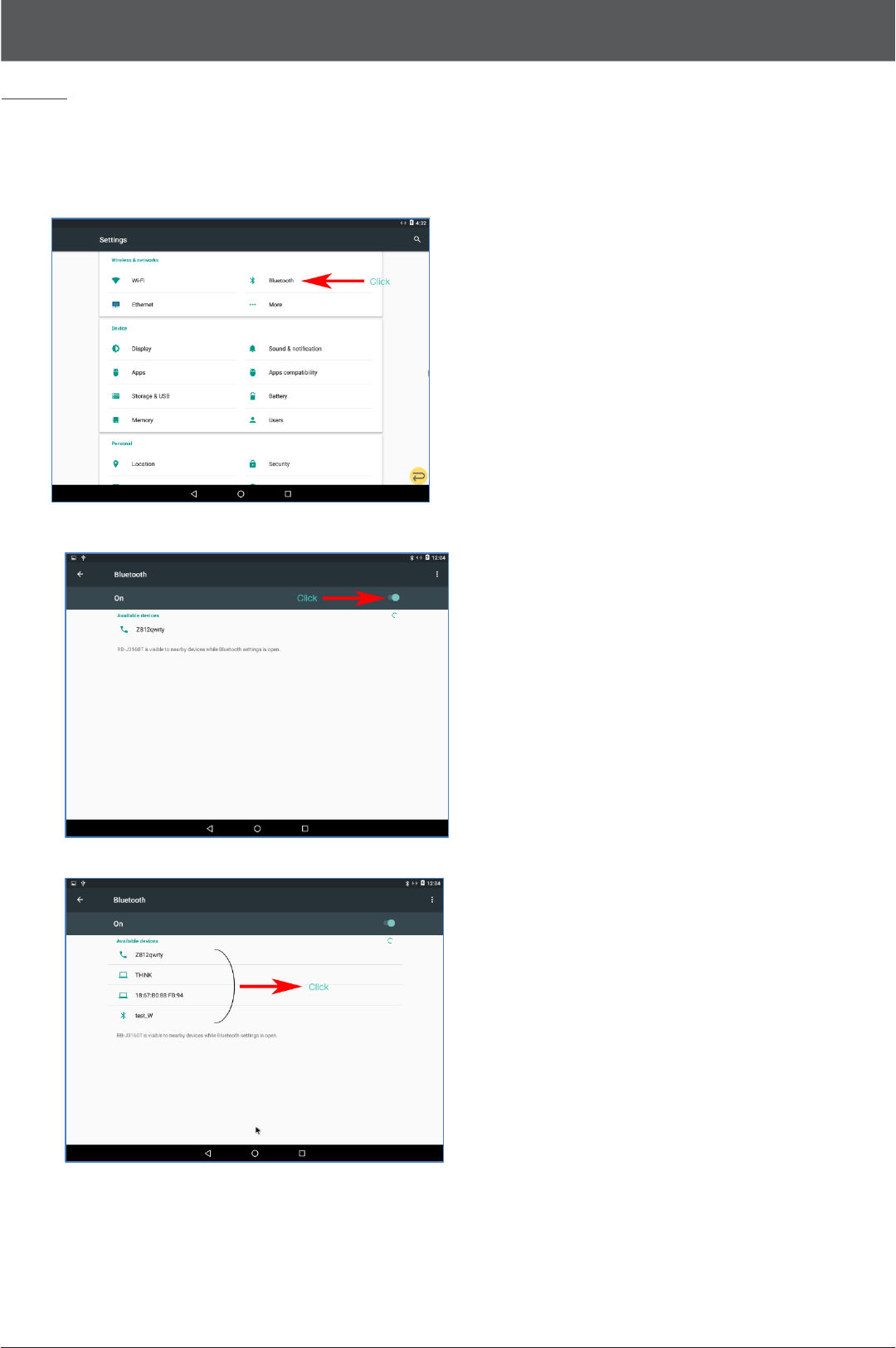
Part 3.
System Settings
04.
Bluetooth
1. Click the Bluetooth menu as bellow
2. Turn on the Bluetooth
3. Select your Device