Shinko Electric Co SSOHT300VHTCOM OHT Vehicle User Manual
Shinko Electric Co Ltd OHT Vehicle Users Manual
UserManual.wiki
>
Shinko Electric Co
>
SSOHT300VHTCOM User Manual
Users Manual
Navigation menu
Upload a User Manual
Namespaces
Wiki Guide
HTML
PDF
Info
Views
User Manual
Discussion / Help
Navigation

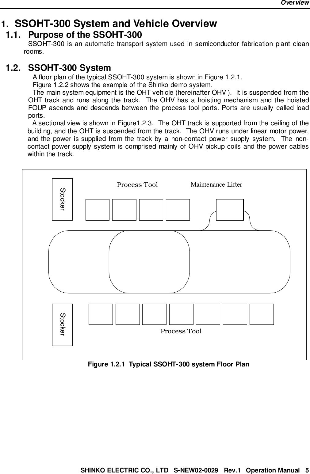

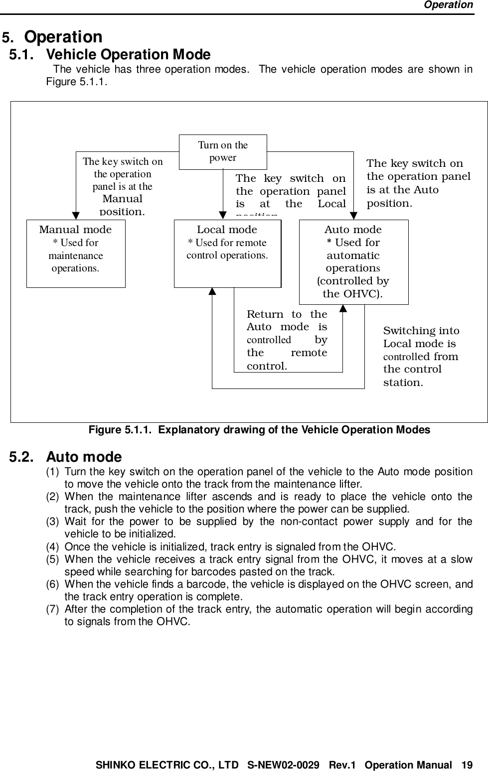
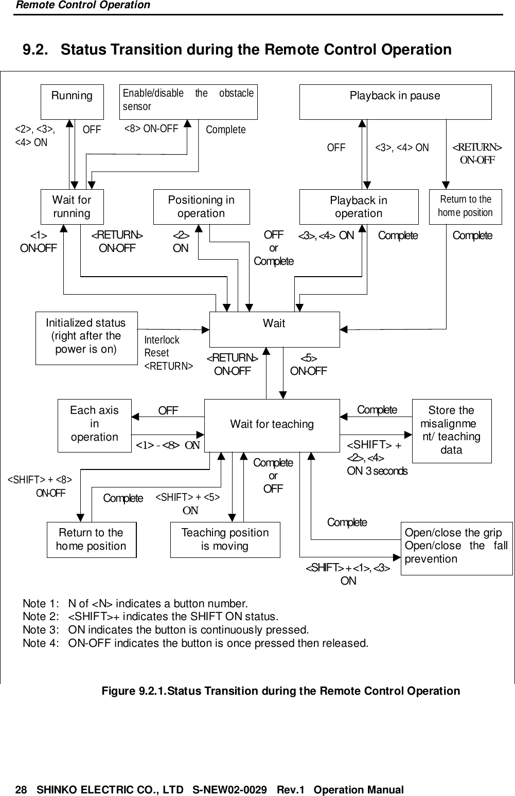
![Emergency Stop ProceduresSHINKO ELECTRIC CO., LTD S-NEW02-0029 Rev.1 Operation Manual 174. Emergency Stop Procedures4.1. EMO (Emergency Off)4.1.1. Location of EMOThe SSOHT-300 system EMO button is located on the front of the power supply panel,which is usually installed on the wall under the track in a clean room.Note: There is not an EMO button on the vehicle.4.1.2. EMO OperationPower to the entire SSOHT-300 system will be shut off when the button is pressed.Power to the power supply panel, maintenance lifter and the OHVC will be shut off.The power supply for all of the vehicles in the system is shut off, and the vehicles willcoast to a rest.Exception: The UPS (Un-interruptible Power Supply) for the OHVC will not be cutoff at that point.The UPS will be shut off after processed data is saved.[For customers considering FAB operation, the location to install the EMO switchneeds to be decided.]4.2. Vehicle Stop Button4.2.1. The Vehicle Stop (emergency stop) Button on the VehicleA vehicle stop button is installed on each vehicle. By pressing this button, the powersupply to the drivers for the vehicle's main four axes (X axis, Z axis, M1 and M2 axes)will be cut and the vehicle will stop operation (the X axis will coast to a stop.)](https://usermanual.wiki/Shinko-Electric-Co/SSOHT300VHTCOM/User-Guide-245487-Page-17.png)