Shinko Electric Co SSOHT300VHTCOM OHT Vehicle User Manual
Shinko Electric Co Ltd OHT Vehicle Users Manual
Users Manual

SHINKO ELECTRIC CO., LTD YTEM-3518 Rev.1 Operation Manual 1
SSOHT-300 System
Vehicle Operation Manual
S-NEW02-0029
Revision 0
Apr. 26, 2002
The information furnished herein by SHINKO ELECTRIC CO.,LTD. is proprietary and confidential to
SHINKO ELECTRIC CO.,LTD. personnel and is not to be duplicated, published, or disclosed to
any third party in whole or in part without permission from SHINKO ELECTRIC CO.,LTD.
Copyright© 1999 SHINKO ELECTRIC CO., LTD. ALL RIGHTS RESERVED.
Unpublished rights reserved under the copyright laws of the United States.
2 SHINKO ELECTRIC CO., LTD S-NEW02-0029 Rev.1 Operation Manual
The information contained herein is provided pursuant to the terms of a License, Non-
disclosure and/or Confidentiality Agreement and constitutes and contains valuable
proprietary information and trade secrets of SHINKO ELECTRIC CO., LTD. embodying
substantial creative efforts and confidential information, ideas, and expressions. Accordingly,
strict compliance with the terms and conditions of the governing Agreement, including,
without limitation, all restrictions on use and disclosure, is required as a condition to the use
of the information contained herein. Except as may be permitted in the applicable
Agreement, the information herein may not be reproduced or disclosed in whole or in part.
Restricted Rights Legend
Use, duplication, or disclosure by the Government is subject to restrictions as set forth in
subparagraph <c> (1) (ii) of the Rights in Technical Data and Computer Software clause at
DFARS 252.277-7013
SHINKO ELECTRIC CO., LTD.
100 Takegahana, Ise city,
Mie prefecture,
516-8550, Japan
Telephone: +81-596-36-3180
Facsimile: +81-596-36-3974

Contents
SHINKO ELECTRIC CO., LTD S-NEW02-0029 Rev.1 Operation Manual 3
Contents
1. SSOHT-300 System and Vehicle Overview................ 5
1.1. Purpose of the SSOHT-300 ............................................... 5
1.2. SSOHT-300 System ........................................................... 5
1.3. Non-Contact Power Supply............................................... 8
1.4. FCC (Federal Communications Commission)
Regulation (provisional) .............................................................. 8
1.5. Notice and Warning of FCC (provisional)......................... 9
2. OHT Vehicle ............................................................... 11
2.1. External Appearance of the OHT Vehicle....................... 11
2.2. Parts Name and Function................................................ 12
2.2.1. Vehicle Body............................................................................... 12
2.2.2. Bumper........................................................................................ 12
2.2.3. Vehicle Stop Switch.................................................................... 12
2.2.4. Fall Prevention Mechanism ........................................................ 12
2.2.5. Front Monitor Sensor.................................................................. 12
2.2.6. Display Panel and Operation Panel............................................ 13
3. Specifications............................................................ 15
3.1. General Specifications.................................................... 15
3.1.1. Wafer Carrier............................................................................... 15
3.1.2. Transport Unit............................................................................. 15
3.1.3. Environmental Condition (Needs a review!! )............................. 15
3.2. Basic Technology Specifications.................................... 16
4. Emgergency Stop Procedures ................................. 17
4.1. EMO (Emergency Off)...................................................... 17
4.1.1. Location of EMO ......................................................................... 17
4.1.2. EMO Operation............................................................................ 17
4.2. The Stop Button on the Vehicle...................................... 17
4.2.1. The Vehicle Stop (emergency stop) Button on the Vehicle........ 17
5. Operation ................................................................... 19
5.1. Vehicle Operation Mode .................................................. 19
5.2. Auto mode........................................................................ 19
5.3. Local mode ...................................................................... 20

Contents
4 SHINKO ELECTRIC CO., LTD S-NEW02-0029 Rev.1 Operation Manual
6. Teaching..................................................................... 21
6.1. References....................................................................... 21
6.2. Two Types of Teaching.................................................... 21
6.3. Remote Control Box ........................................................ 22
7. Preparation ................................................................ 23
7.1. Preparation of the OHT Vehicle ...................................... 23
7.2. Preparation of the Remote Control Box ......................... 23
7.3. Registration of a Vehicle F Number................................ 23
7.3.1. Confirmation of the DIP Switches of the Remote Control
Switches ..................................................................................... 24
7.3.2. Registration of F Number ........................................................... 24
8. Remote Control Box Position................................... 25
9. Remote Control Operation........................................ 27
9.1. Remote Control Operation List....................................... 27
9.2. Status Transition during the Remote Control
Operation.................................................................................... 28
9.3. Basic Button Operation................................................... 29
9.4. Remote Control Operation Button Assignment............. 29
9.4.1. Function Button.......................................................................... 29
9.4.2. Operation Button ........................................................................ 29
10. Installation and Removal of the Vehicle .................. 33
10.1. Vehicle Exchange on the Track....................................... 33
10.1.1. Installation of the Vehicle ........................................................... 33
10.1.2. Removal of the Vehicle............................................................... 33
11. Error Recovery Procedures...................................... 35

Overview
SHINKO ELECTRIC CO., LTD S-NEW02-0029 Rev.1 Operation Manual 5
1. SSOHT-300 System and Vehicle Overview
1.1. Purpose of the SSOHT-300
SSOHT-300 is an automatic transport system used in semiconductor fabrication plant clean
rooms.
1.2. SSOHT-300 System
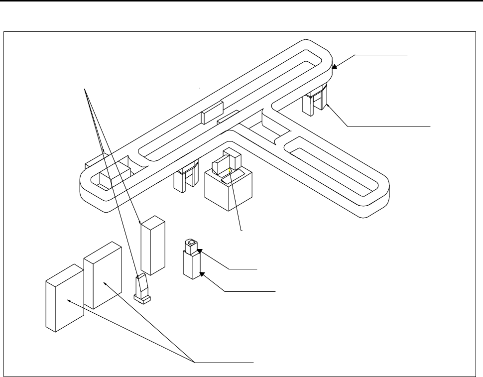
A floor plan of the typical SSOHT-300 system is shown in Figure 1.2.1.
Figure 1.2.2 shows the example of the Shinko demo system.
The main system equipment is the OHT vehicle (hereinafter OHV ). It is suspended from the
OHT track and runs along the track. The OHV has a hoisting mechanism and the hoisted
FOUP ascends and descends between the process tool ports. Ports are usually called load
ports.
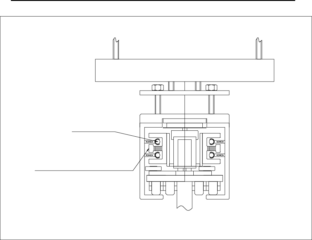
A sectional view is shown in Figure1.2.3. The OHT track is supported from the ceiling of the
building, and the OHT is suspended from the track. The OHV runs under linear motor power,
and the power is supplied from the track by a non-contact power supply system. The non-
contact power supply system is comprised mainly of OHV pickup coils and the power cables
within the track.
Figure 1.2.1 Typical SSOHT-300 system Floor Plan
Stocker Stocker
Process Tool
Process Tool
Maintenance Lifter
Overview
6 SHINKO ELECTRIC CO., LTD S-NEW02-0029 Rev.1 Operation Manual
Figure 1.2.2 Shinko Demo System Example
OHT Vehicle
Maintenance Lifter
OHVC
Ground Power Supply Panel
OHT Track
FOUP
Process tool
Overview
SHINKO ELECTRIC CO., LTD S-NEW02-0029 Rev.1 Operation Manual 7
Figure 1.2.3 Sectional View
Cable
Pickup Coil
Overview
8 SHINKO ELECTRIC CO., LTD S-NEW02-0029 Rev.1 Operation Manual
1.3. Non-Contact Power Supply
The non-contact power supply is an electromagnetic coupling and can be understood
as a special type of transformer. It supplies power to the OHV. The track is equipped
with power cables, and is constantly supplied with an alternating current from the power
supply panel on the ground. Shinko uses an 8.66 kHz alternating current as a main
power source.
Signals of approximately 300kHz and 350kHz are used for communication between
the OHV and ground controller on top of the 8.66kHz for the main components.
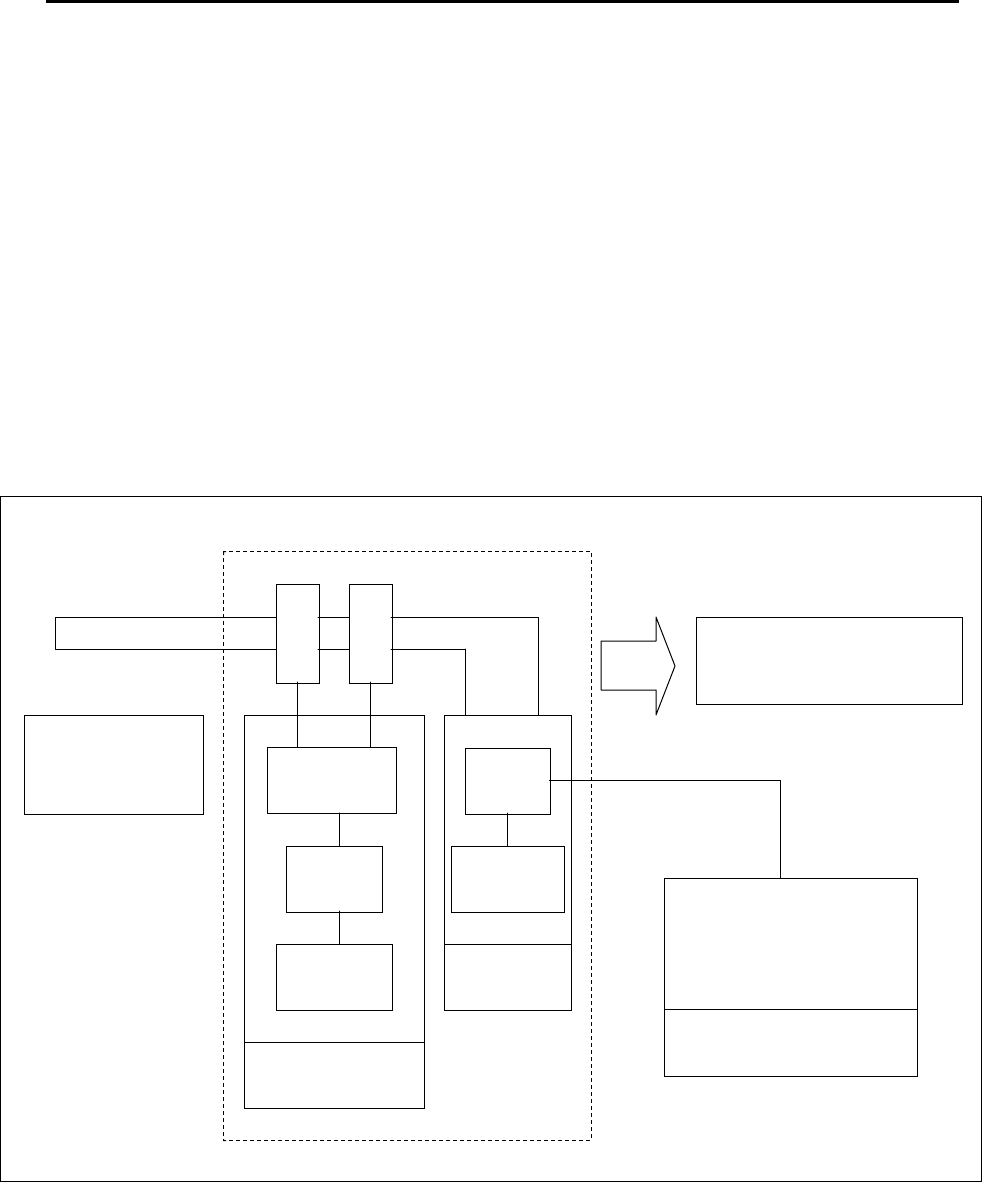
1.4. FCC (Federal Communications Commission) Regulation
(provisional)
FCC regulations for the Shinko SSOHT-300 system and the SSOHT-300 system: there
are two applicable FCC regulations. Section 15 (c), and the section concerning
intentional radiator is applicable.
Section 18 applies to the power supply and relevant component parts (Refer to Figure
1.4.1).
Figure 1.4.1 FCC Regulations and the OHT Configuration
Communi
cation
Maintenance
Lifter
CPU
Servo,
etc.
OHT Vehicle
CMC
Power
Supply
Power
Supply
Section 15
(C):Intentional, radiator
OHVC
(OHT Vehicle
Controller)
(FCC approved)

Overview
SHINKO ELECTRIC CO., LTD S-NEW02-0029 Rev.1 Operation Manual 9
1.5. FCC Notice and Warning (provisional)
Notice
Based on test results, this system was determined to conform to the class A limit for digital
devices in accordance with FCC regulation Section 15.
Such a limit has the purpose of sufficiently preventing harmful interference when the equipment
is used in a business-operating environment.
This equipment generates, uses, and may radiate high frequency energy. If it is not installed or
used according to the instruction manual, it may cause harmful interference to wireless
communication.
Use of this equipment in a residential area may cause harmful interference in which case the
user is required to correct the interference at their own expense.
FCC Warning
If any changes or modifications are made without explicit approval of the party involved who is
responsible for regulatory compliance, the user's right to use the equipment may be revoked.

Overview
10 SHINKO ELECTRIC CO., LTD S-NEW02-0029 Rev.1 Operation Manual
Intentionally left blank.
Vehicle
SHINKO ELECTRIC CO., LTD S-NEW02-0029 Rev.1 Operation Manual 11
2. OHT Vehicle
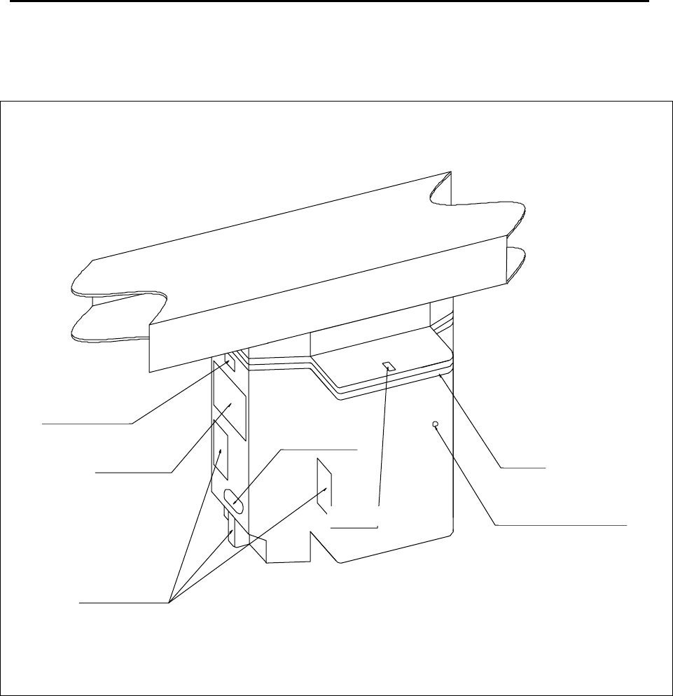
2.1. External Appearance of the OHT Vehicle
Figure 2.1.1. External View of the OHT Vehicle
The external view of the OHT vehicle is shown in Figure 2.1.1.
Bumper
Vehicle Stop Button
Optical I/O
Operation Panel
Obstacle Sensors
Display Panel
Front Sensor

Vehicle
12 SHINKO ELECTRIC CO., LTD S-NEW02-0029 Rev.1 Operation Manual
2.2. Part Names and Function
2.2.1. Vehicle Body
The vehicle is comprised of X, Y, , and Z axis. The X axis is for moving the vehicle,
and the Y-mechanism is comprised of the M1 and M2 axes. Operating the M1 and
M2 axes enables movements in the Y direction (horizontal movement of the vehicle
body) and the direction (rotation of the vehicle body). The Z axis moves the gripper
up and down.
The X axis is driven by a linear motor, the M1 and M2 axes by an AC servomotor, the Z
axis by an AC servomotor, and opening/closing of the gripper by a brush-less DC motor.
The gripper is suspended by four belts that are reinforced with steel wires.
2.2.2. Bumper
The bumper is a contact tape switch and is installed around the vehicle. When this
comes into contact with any obstacle, the power supply to the drivers for main four axes
(X axis, M1 and M2 axes, and Z axis) will be shut off. For safety purposes, two bumper
switches are installed in parallel.
2.2.3. Vehicle Stop Switch
The vehicle is equipped with a vehicle stop button. Pressing this button will shut off
the power supply to the drivers for the main four axes just like the bumpers do.
2.2.4. Fall Prevention Mechanism
The vehicle is equipped with fall prevention arms. If the FOUP falls while running, the
arms prevent the FOUP from falling.
2.2.5. Front Monitor Sensor
At the front of the vehicle, there are obstacle sensors (right, down, and side. Up and
left sensors are optional), an approaching sensor, a straight travel block sensor, a
curve travel block sensor, a dead zone sensor, a front vehicle detection sensor, and a
front vehicle confirmation sensor.
The obstacle sensors are adjusted at 2.8m for the slowdown signal output distance
and 0.8m for the stop signal output distance.
The approaching sensor is adjusted to send a stop signal when the vehicle comes to
0.3m.
The straight travel block sensor and the curve travel block sensor are attached to the
Y- mechanism part, and their receivers are installed on the vehicle. The transmitters
are installed on the track (the straight travel block sensor transmitters on the straight
area, and the curve travel block sensor transmitters on the curved area), and when
beams emitted by the transmitters are received, each sensor sends stop signals.
The dead zone sensor is optional. The detection distance is adjusted at 15cm.
The front vehicle detection sensor's receiver and transmitter are installed respectively
at the front and back of the vehicle running part bogie and used for detecting a vehicle
ahead.
The front vehicle confirmation sensor's receiver and transmitter are also installed
respectively at the side front and side back of the vehicle and are used for detecting a
vehicle in front when running on the straight track.
Vehicle
SHINKO ELECTRIC CO., LTD S-NEW02-0029 Rev.1 Operation Manual 13
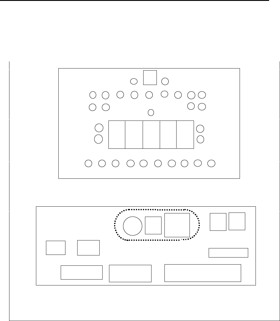
2.2.6. Display Panel and Operation Panel
The display panel and the operation panel are shown in Figures 2.2.6.1 and 2.2.6.2,
respectively. The meaning of the display panel LED and the operation panel parts are
described in Tables 2.2.6.1 and 2.2.6.2.
Figure 2.2.6.1 Display Panel
Figure 2.2.6.2 Operation Panel
LED1
LED2
LED3
LED4
LED5 LED6
LED7
LED8
LED9
LED10
LED11
LED12
LED13
LED14 LED15
LED16
LED17
LED18
LED19
LED20
LED21
LED22
LED23
LED24
LED25
LED26
LED27
LED28
LED29
LED30
SW1
7SEG
2
7SEG
3
7SEG
4
7SEG
5
7SEG
1
SW106
SW
104
SW
103 SW
102
SW
101
CNP112
CNP
108
CNP103
CNP106
CNP04
CNP01

Vehicle
14 SHINKO ELECTRIC CO., LTD S-NEW02-0029 Rev.1 Operation Manual
Figure 2.2.6.1. Meaning of the Indicator LED
LED
No Color Meaning LED
No Color Meaning
1Gree
n16 Red Illuminates when error occurs.
2Gree
n17 Green Illuminates at the front M/D roller right
(facing the direction of travel)
position.
3Gree
n18 Green Illuminates at the back M/D roller
right position.
4Gree
n
Illumination controlled by the
CPU.
For monitoring control status
(Ex: remote control status).
19 Green Illuminates at the front M/D roller left
position.
5Gree
nIlluminates when detecting a
load on the FOUP. 20 Green Illuminates at the back M/D roller left
position.
6Gree
nIlluminates when detecting a
load on the FOUP. 21 Green
7Gree
nIlluminates when the gripper is
closed. 22 Green The obstacle sensor (or valid sensor
) is far.
8Gree
nIlluminates when the gripper is
open. 23 Green The obstacle sensor (or valid sensor
) is near.
9Gree
nFall prevention 24 Green Illuminates when the sensor
responds.
10 Gree
nIlluminates when the fall
prevention mechanism is
closed.
25 Green Illuminates at detection by the dead
zone sensor.
11 Gree
nFOUP fall is detected. 26 Green The curve travel block sensor
12 Gree
nIlluminates when
communication is received. 27 Green The straight travel block sensor.
13 Gree
nIlluminates when
communication is sent. 28 Green The front vehicle detection sensor
(far)
14 Gree
nGuide rail left status display 29 Green The front vehicle detection sensor
(near)
15 Gree
nGuide rail right status display 30 Green Front vehicle check
7SEG1-5:
SW1: Switch for checking lamps. When the switch is on, all LED and 7SEG will light up.
Table 2.2.6.2. Panel - 02 Parts Description
Connector
Number Use Switch
Number Use
CNP01 24V external input SW101 Vehicle status selection switch
The key can be removed at the
AUTO (center) position.
CNP04 Manual break operation input SW102 E84
CNP103 Gripping, fall prevention, and the
M/D roller manual operation SW103 Error reset
CNP106 Debugging and FDD connection SW104 CPU reset
CNP108 Teaching communication (option) SW106 232C input switch
1: PB9-07
(Lookdown sensor)
2: PB-10Z
3: CPU232C
CNP112 232C input

Specifications
SHINKO ELECTRIC CO., LTD S-NEW02-0029 Rev.1 Operation Manual 15
3. Specifications
3.1. General Specifications
3.1.1. Wafer Carrier
Name 300mm wafer FOUP
Type
Manufacturer
Material SEMI E47.1-0299(1999) compliant
Color SEMI E47.1-0299(1999) compliant
Weight 8.7kg-f (Max. including 25 wafers)
Dimensions 430mm(width) × 356mm (depth) ×
338mm (height)
External Shape SEMI E47.1-0299(1999) compliant
3.1.2. Transport Unit
One FOUP per one vehicle.
3.1.3. Environmental Condition
Cleanliness Class 100 (0.1µm)
Temperature 15-25°C
Humidity ↓%
Corrosive Gas None
Floor Surface Punching plate
Ceiling Material ULPA filter
Ceiling Height 12 feet
Desired Strength for
the Ceiling Height ↓

Specifications
16 SHINKO ELECTRIC CO., LTD S-NEW02-0029 Rev.1 Operation Manual
3.2. Basic Technology Specifications
Table 3.2.1 Basic Specifications
Item Specifications
External Dimensions 440 (W) x 675 (L) x 936 (H: including the track)
Weight 97Kg (no load)
Receiving System Non-contact power supply system (8.6kHz)
Power Consumption Max. 500w
Transpor
t Control Ground command by the OHVCControl System
Running
Control Self-control by barcodes and the front monitor sensor.
Merge/diverge control by the guide rail.
Merge/Diverge
Method M/D rollers and M/D guide.
Communication
Method Power line communication method, 19,200bps (FCC compliant)
Four axes (X axis, Z axis, M1 and M2 axes)
X axis (run) LSM
(Two motors are serially-connected)
Z axis
(up/down) 200w AC servomotor
Main Driving Axis
M1 and M2
axes
(Y-)
30w AC servomotor (2 units)
Straight line speed: 2.0, 1.5, 1.0, 0.4, 0.2, 0.05
(m/s)
Curved line speed: 0.4 (m/s)
Running Speed
Reverse travel (enabled only in the remote
control operation): 0.2m/s
Acceleration: ±1m/s2
Minimum Curve
Radius 0.5m
Ascending/Descendin
g Speed Max. 1.0m/s (adjustable speed 1m/s2)
Loaded Weight Max. 10kg (one unit of the FOUP fully loaded with 300mm)
X direction 0.1mm
Y direction 0.1mm
direction 0.1°
Positioning Resolution
(Command resolution)
Z direction 0.1mm
Position Correction Y direction: ±30mm; direction (rotation): ±10°
Cleanliness 0.1µm, Class 100
Operating
Environment Ambient temperature: 15C-25C; Humidity:
Ascending/Descendin
g Stroke Max. 2700mm
Traveling Direction Top view counter-clockwise.
Cover Flame-retardant material Roa (Tsutsunaka Plastic Industry) (Synthetic
material made of V0 class ABS and polycarbonate)
Distance between the
mark sensor and the
transfer center point
150mm (The distance between the stop mark (black bar edge) and the
transfer center point is 150mm.)
Optical I/O Position 250mm from the center of the track.
Complied Standards JIS, UL, CE, (SEMI S2)

Emergency Stop Procedures
SHINKO ELECTRIC CO., LTD S-NEW02-0029 Rev.1 Operation Manual 17
4. Emergency Stop Procedures
4.1. EMO (Emergency Off)
4.1.1. Location of EMO
The SSOHT-300 system EMO button is located on the front of the power supply panel,
which is usually installed on the wall under the track in a clean room.
Note: There is not an EMO button on the vehicle.
4.1.2. EMO Operation
Power to the entire SSOHT-300 system will be shut off when the button is pressed.
Power to the power supply panel, maintenance lifter and the OHVC will be shut off.
The power supply for all of the vehicles in the system is shut off, and the vehicles will
coast to a rest.
Exception: The UPS (Un-interruptible Power Supply) for the OHVC will not be cut
off at that point.
The UPS will be shut off after processed data is saved.
[For customers considering FAB operation, the location to install the EMO switch
needs to be decided.]
4.2. Vehicle Stop Button
4.2.1. The Vehicle Stop (emergency stop) Button on the Vehicle
A vehicle stop button is installed on each vehicle. By pressing this button, the power
supply to the drivers for the vehicle's main four axes (X axis, Z axis, M1 and M2 axes)
will be cut and the vehicle will stop operation (the X axis will coast to a stop.)

Emergency Stop Procedures
18 SHINKO ELECTRIC CO., LTD S-NEW02-0029 Rev.1 Operation Manual
Intentionally left blank.
Operation
SHINKO ELECTRIC CO., LTD S-NEW02-0029 Rev.1 Operation Manual 19
5. Operation
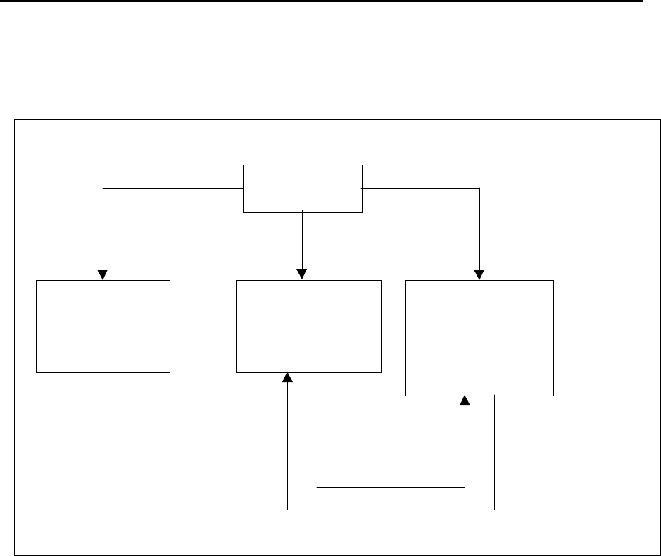
5.1. Vehicle Operation Mode
The vehicle has three operation modes. The vehicle operation modes are shown in
Figure 5.1.1.
Figure 5.1.1. Explanatory drawing of the Vehicle Operation Modes
5.2. Auto mode
(1) Turn the key switch on the operation panel of the vehicle to the Auto mode position
to move the vehicle onto the track from the maintenance lifter.
(2) When the maintenance lifter ascends and is ready to place the vehicle onto the
track, push the vehicle to the position where the power can be supplied.
(3) Wait for the power to be supplied by the non-contact power supply and for the
vehicle to be initialized.
(4) Once the vehicle is initialized, track entry is signaled from the OHVC.
(5) When the vehicle receives a track entry signal from the OHVC, it moves at a slow
speed while searching for barcodes pasted on the track.
(6) When the vehicle finds a barcode, the vehicle is displayed on the OHVC screen, and
the track entry operation is complete.
(7) After the completion of the track entry, the automatic operation will begin according
to signals from the OHVC.
Turn on the
power
Manual mode
* Used for
maintenance
operations.
Local mode
* Used for remote
control operations.
Auto mode
* Used for
automatic
operations
(controlled by
the OHVC).
The key switch on
the operation
panel is at the
Manual
position.
The key switch on
the operation panel
is at the Local
position
T
he key switch on
the operation panel
is at the Auto
position.
Return to the
Auto mode is
controlled by
the remote
control.
Switching into
Local mode is
controlled from
the control
station.

Operation
20 SHINKO ELECTRIC CO., LTD S-NEW02-0029 Rev.1 Operation Manual
5.3. Local mode
In this mode, the vehicle is controlled by the remote control box.
There are two ways to switch into this mode.
(1) Turn the key switch on the control panel to "Local."
(2) Send a signal from the OHVC to change to "Local."
For operating the remote control box, please refer to the "Remote Box Control
Instruction Manual."

Teaching
SHINKO ELECTRIC CO., LTD S-NEW02-0029 Rev.1 Operation Manual 21
6. Teaching
6.1. References
1 Teaching Instruction Manual
2 Remote Control Box Specifications
3 Remote Control Box Instruction Manual
6.2. Two Types of Teaching
There are two types of teaching method.
(1) Manual teaching (Standard)
In manual teaching, the operator uses the remote control to teach the
equipment.
(2) Semi-automatic teaching (option)
Set the LED for target at the bottom of the gripper, and set the PSD (position
sensing device) at the load port.
The gripper comes down to just above the height of FOUP. By looking at the
LED, the PSD detects a misalignment of the FOUP center and the load port
FOUP center.
The teaching controller sends a message to tell the vehicle to correct its
position. The vehicle moves the X axis and the M1/M2 axes (Y- direction) to
reduce the misalignment to 0.
The vehicle stores this teaching information as position data.
Teaching
22 SHINKO ELECTRIC CO., LTD S-NEW02-0029 Rev.1 Operation Manual
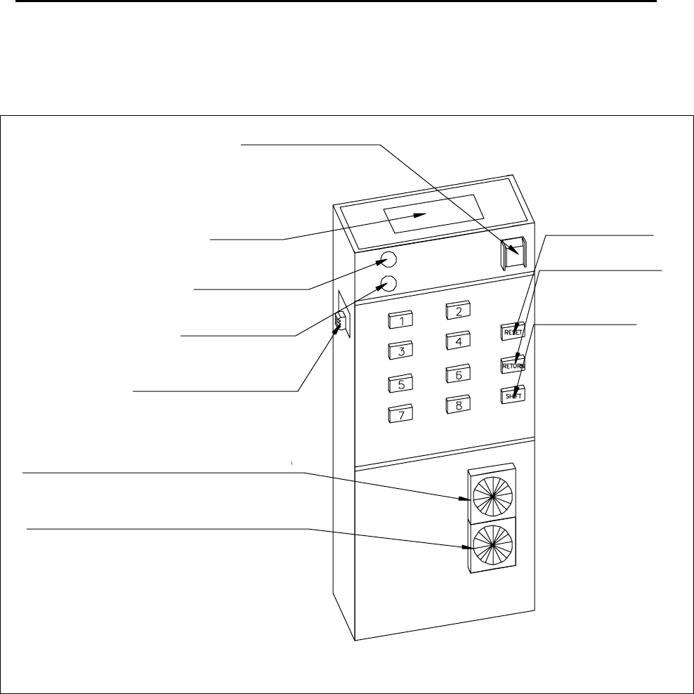
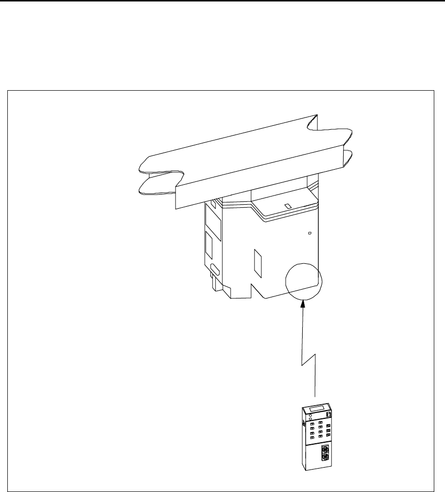
6.3. Remote Control Box
The external appearance and part names of the remote control box is shown in Figure
6.3.1. Figure 6.3.1. External Appearance of the Remote Control Box
Vehicle Stop Button
Signal Output Part
Signal Output LED
Battery Change LED
Power ON/OFF Switch
Rotary Switch for Vehicle Number Setting (lower)
Rotary Switch for Vehicle Number Setting (upper)
Reset Button
Return Button
Shift Button
Preparation
SHINKO ELECTRIC CO., LTD S-NEW02-0029 Rev.1 Operation Manual 23
7. Preparation
Preparation for remote control operations is described below.
7.1. Preparation of the OHT Vehicle
The OHT vehicle has three modes.
(1) Manual mode---------Maintenance purposes only
(2) Auto mode------------Automatic running mode
(3) Local mode-----------Remote control operation mode
Remote control operations are performed in the (3) Local mode.
There are two ways to switch from the Auto mode into the Local mode.
(1) Turn the key switch on the operation panel to the “Local” position.
(2) Send a signal from the OHVC to switch to the “Local” mode.
7.2. Preparation of the Remote Control Box
The rotary switch of the remote control box must be set to the same number as the F-
number of the remote control receiver on the vehicle side.
The setting must be done, after selecting the selection range of the F-number, according
to the following procedures.
(1) The setting can be done by using the two rotary switches (Refer to Figure 6.3.1).
Setting Range: 01-FF (01-255)
(2) Turn on the power of the remote control box.
7.3. Registration of a Vehicle F Number
Danger
Maintenance and teaching must be performed by personnel
who have received maintenance and teaching training.
Preparation
24 SHINKO ELECTRIC CO., LTD S-NEW02-0029 Rev.1 Operation Manual
7.3.1. Confirmation of the DIP Switches of the Remote Control Switches
Remove the back cover of the remote control box and set or confirm the DIPswitches as
shown below.
Figure 7.3.1.1. Back View and the DIPSwitch of the Remote Control Box
7.3.2. Registration of F Number
The method for registering the F-number to the remote control receiver on the vehicle
side is described below.
(1) When removing the rubber cap of the remote control box, the mode switch (slide
switch) will appear. Set the switch to the left to change to the write mode.
(2) Registration is done by the transmitter. By pressing the send key for a few seconds,
the F-number set by the transmitter will be sent. In this case, the write signal pilot
lamp of the receiver (WRT) will change from a flashing to a solid light.
(3) After it is registered, switch the mode switch to the normal mode and replace the
rubber cap.
O
N
1
2
3
4
Remote Control Box Position
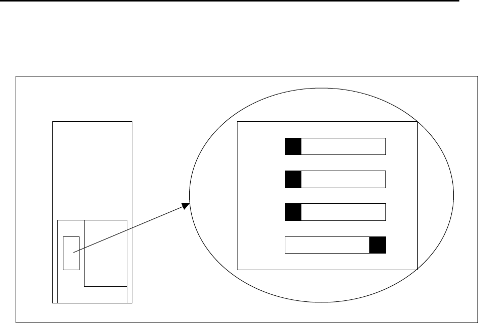
SHINKO ELECTRIC CO., LTD S-NEW02-0029 Rev.1 Operation Manual 25
8. Remote Control Box Position
This remote control box uses infrared light. For remote control operations, the light from the
remote control must be facing toward the receiver of the vehicle. The receiver is located under
the side cover of the vehicle (Refer to Figure 8.1).
Figure 8.1.Remote Control Box Position
There is a remote
control receiver installed
on the back corner of
the vehicle facing down.
Turn the remote control
toward that direction.

Remote Control Box Position
26 SHINKO ELECTRIC CO., LTD S-NEW02-0029 Rev.1 Operation Manual
Intentionally left blank.

Remote Control Operation
SHINKO ELECTRIC CO., LTD S-NEW02-0029 Rev.1 Operation Manual 27
9. Remote Control Operation
9.1. Remote Control Operation List
Table 9.1.Remote Control Function List
Button Mode Button Shift key OFF Status Shift key ON (Note 5) Status
1 M/D roller left TAP
2 M/D roller right TAP
3 Forward creep (0.05m/s) HOLD
4 Reverse travel (-0.2m/s) ↑
5 Run forward at the mid
speed (0.4m/s)
↑
6
7
1Run
Mode
8 Obstacle sensor on/off TAP/
toggle
2 Positioning mode HOLD
3 Playback (loaded) (Note 1) HOLD
4 Playback (unloaded) (Note 1) HOLD
1 Move the X axis forward HOLD Open/close the gripper (Note 2) TAP/
toggle
2 Move the X axis backward ↑Store offset data 3 sec.
3 Move the Y axis forward ↑Open/close the fall prevention
mechanism
TAP/
toggle
4 Move the Y axis in the rear
direction
↑Store teaching data 3 sec.
5 Move the Z axis downward
(slow speed)
↑Move the Z axis to the teaching
position
HOLD
6 Move the Z axis upward
(slow speed)
↑Move the Z axis downward at a
high speed
HOLD
7 Turn the axis clockwise ↑
5 Teaching
mode
8 Turn the axis counter-
clockwise
↑Return to the home position
(Inoperable when the gripper is
open)
HOLD
6 Switch to the HOST mode 3 sec.
7
8 Shutdown (Note 3) 3 sec.
TAP: Press the button once to execute the operation.
HOLD: The operation is executed while the button is being pressed. It pauses when
the button is released.
3 sec.: The operation is executed when the button is pressed for three seconds.
Note 1: Transfer playback occurs while the button is being pressed. Details are as
follows: • It operates while the button is being pressed, and it pauses when the
button is not pressed.
• When pressing the Return (interrupt) button while pausing, the gripper
will be closed, and it returns to the main operation after returning to
the home position.
Note 2: It opens/closes by a TAP when there is no load.
Note 3: MANU (It switches to manual status: All axes servos off)
Switch to this mode when bringing the vehicle into the maintenance station..
Note 4: Data storage complete buzzer
Note 5: When the Shift key is on, LED1 illuminates on the panel.
Remote Control Operation
28 SHINKO ELECTRIC CO., LTD S-NEW02-0029 Rev.1 Operation Manual
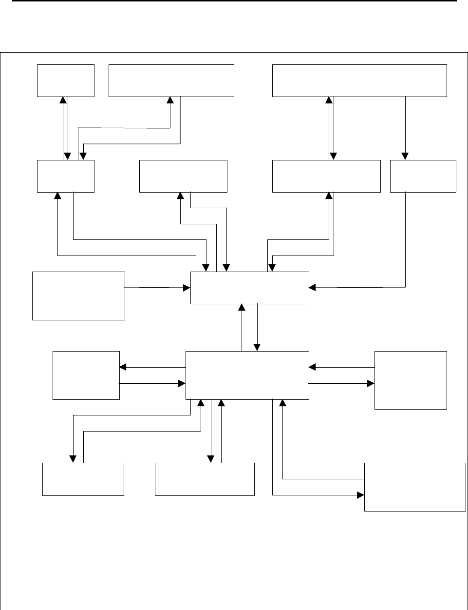
9.2. Status Transition during the Remote Control Operation
Figure 9.2.1.Status Transition during the Remote Control Operation
Initialized status
(right after the
power is on)
Wait
Interlock
Reset
<RETURN>
Wait for
running Positioning in
operation Playback in
o
p
eration Return to the
home position
Wait for teaching
Each axis
in
operation
Return to the
home position Teaching position
is moving Open/close the grip
Open/close the fall
prevention
Store the
misalignme
nt/ teaching
data
Playback in pauseRunning Enable/disable the obstacle
sensor
<1>
ON-OFF <RETURN>
ON-OFF <2>
ON OFF
or
Complete
<2>, <3>,
<4> ON OFF <8> ON-OFF Complete
<3>, <4> ON Complete Complete
OFF <3>, <4> ON <RETURN>
ON-OFF
<RETURN>
ON-OFF <5>
ON-OFF
OFF
<1> - <8> ON
Complete
<SHIFT> + <8>
ON-OFF
Complete
<SHIFT> +
<2>, <4>
ON 3 seconds
<SHIFT> + <5>
ON
Complete
or
OFF
<SHIFT> + <1>, <3>
ON
Complete
Note 1: N of <N> indicates a button number.
Note 2: <SHIFT>+ indicates the SHIFT ON status.
Note 3: ON indicates the button is continuously pressed.
Note 4: ON-OFF indicates the button is once pressed then released.

Remote Control Operation
SHINKO ELECTRIC CO., LTD S-NEW02-0029 Rev.1 Operation Manual 29
9.3. Basic Button Operation
The button operations of the remote control are described below.
(1) By pressing the function buttons and the operation buttons, the corresponding
functions can be performed.
(2) Each time the shift button is pressed, it toggles between Shift ON and Shift
OFF.
(3) When the shift key is on, a different function can be performed by pressing another
button.
(4) Whether the shift key is currently on or off is indicated by LED1 on the panel (When it
is on, the LED illuminates).
9.4. Remote Control Operation Button Assignment
9.4.1. Function Button
The function buttons can perform the functions defined in Table 9.4.1.1.
Table 9.4.1.1 Function Button List
Function Button SHIFT- OFF SHIFT- ON
Vehicle stop button Vehicle emergency stop ---
RESET button Error reset ---
RETURN button Return (or interrupt) ---
9.4.2. Operation Button
Different functions can be assigned by each remote control operation.
9.4.2.1. When Functions are Selected
The function selection buttons are shown in Table 9.4.2.1.1.
Table 9.4.2.1.1. Button Assignment when Functions are selected
Function Button SHIFT- OFF SHIFT- ON
1 Running operation ---
2 Positioning run ---
3 Load playback operation ---
4 Unload playback operation ---
5 Teaching operation ---
6 Switch to the HOST mode ---
7 --- ---
8 --- ---
9.4.2.2. In Running Operation
Button assignment in the running operation is shown in the table 9.4.2.2.1.
Table 9.4.2.2.1. Button Assignment in the Running Operation
Function Button SHIFT- OFF SHIFT- ON
1 M/D roller left ---
2 M/D roller right ---
3 Forward at the first speed
(slow speed) ---
4 Backward at the first speed
(0.2m/s) ---
5 Forward at the second
speed (0.4m/s) ---
6 --- ---
7 --- ---
8 Obstacle sensor on/off ---

Remote Control Operation
30 SHINKO ELECTRIC CO., LTD S-NEW02-0029 Rev.1 Operation Manual
9.4.2.3. In Transfer Teaching
Button assignment in transfer teaching is shown in Table 9.4.2.3.1.
Table 9.4.2.3.1. Button Assignment in Transfer Teaching
Function Button SHIFT- OFF SHIFT- ON
1 Move in the X direction
(forward) Open/close the gripper
2 Move in the X direction
(backward) Store offset data
3 Move in the Y direction
(front, vehicle left side) Open/close the fall
prevention mechanism
4 Move in the Y direction
(rear, vehicle right side) Store teaching data
5 Move in the Z direction
(downward) Lower the teaching
position
6 Move in the Z direction
(upward) ---
7 Move in the direction (CW) ---
8 Move in the direction
(CCW) Return to the home
position
9.4.2.4. Exceptional Operation Button
Exceptional operation buttons are shown below.
9.4.2.4.1. Before Initial Waiting
Assignment of the interlock reset button when returning to the home position before the
initial waiting is shown in Table9.4.2.4.1.1.
Table 9.4.2.4.1.1. Button Assignment before Initial Waiting
Function Button SHIFT- OFF SHIFT- ON
1 Grip open Note 1 ---
2 --- ---
3 --- ---
4 --- ---
5 --- ---
6 --- ---
7 --- ---
8 --- ---
RETURN Interlock Reset Note 2 ---
Note 1: Opening of the grip is possible when there is no load. When there is a load, it
becomes an error.
Note 2: When the gripping part is not at its home position, the interlock will be stopped.
This button is used to reset this condition.

Remote Control Operation
SHINKO ELECTRIC CO., LTD S-NEW02-0029 Rev.1 Operation Manual 31
9.4.2.4.2. When an Error Occurs
Button assignment when an error has occurred is shown in Table 9.4.2.4.2.1.
Table 9.4.2.4.2.1 Button Assignment when an Error Occurred
Function Buttons SHIFT- OFF SHIFT- ON
1 M/D roller left ---
2 M/D roller right ---
3 --- ---
4 --- ---
5 --- ---
6 --- ---
7 --- ---
8 --- ---
RESET Error Reset ---

Remote Control Operation
32 SHINKO ELECTRIC CO., LTD S-NEW02-0029 Rev.1 Operation Manual
Intentionally left blank.

Installation and Removal of the Vehicle
SHINKO ELECTRIC CO., LTD S-NEW02-0029 Rev.1 Operation Manual 33
10.
Installation and Removal of the Vehicle
Install and remove the vehicle onto/from the OHT track using the maintenance lifter.
10.1. Vehicle Exchange on the Track
10.1.1. Installation of the Vehicle
(1) A backup vehicle is loaded onto the vehicle cart. Move this backup vehicle to the
maintenance lifter.
(2) Connect the lifter operation panel to the connector on the ground.
(3) Turn on the key switch on the lifter operation panel to turn on the power to the
operation panel.
(4) When the operation panel menu screen is displayed, press Manual and perform the
following operations.
(5) Lower the lifter rail and connect it to the vehicle cart.
(6) Move the vehicle manually from the vehicle cart onto the lifter. When doing this,
make sure that you press the vehicle stopper on the lifter to release it.
(7) Bring the lifter up with the backup vehicle loaded.
(8) When the lifter reaches the top, the UP button will illuminate. Lock the lifter stopper
and release the vehicle stopper.
(9) Use the push bar to move the vehicle manually to the position on the track where
non-contact power can be supplied.
(10) Once a series of operations is completed, turn off the key switch on the operation
panel and disconnect the connector.
10.1.2. Vehicle Removal
(1) Move the vehicle on the lifter rail manually using the push bar.
(2) Connect the lifter operation panel connector and the connector on the ground. After
connecting them, turn the key switch on the operation panel on, and wait for the
menu screen to be displayed.
(3) When the menu screen is displayed, lower the lift and connect the vehicle cart and
the lifter.
(4) Move the vehicle manually from the lifter onto the vehicle cart.
(5) Bring up the lifter.
(6) When the lifter reaches the top, lock the lifter stopper and release the vehicle
stopper, then turn off the key switch on the operation panel and disconnect the
connector.
Warning
Do not install/remove the vehicle when the FOUP is loaded on.
Do not go into the operation area of the maintenance shifter/lifter.

Installation and Removal of the Vehicle
34 SHINKO ELECTRIC CO., LTD S-NEW02-0029 Rev.1 Operation Manual
Intentionally left blank.
Error Recovery Procedures
SHINKO ELECTRIC CO., LTD S-NEW02-0029 Rev.1 Operation Manual 35
11.
Error Recovery Procedures
Recovery procedures when an error has occurred are described below.
(1) An error has occurred.
(2) Check the error condition.
(3)
Make sure that you keep the vehicle log with more than 2000 entries and the OHVC
communication log with more than 1000 entries.………Note 1
(4) Ref er to the troubleshooting section of the "Maintenance Manual" for the error condition
and perform an error recovery.
(5) If an immediate recovery is difficult, move the vehicle to the maintenance lifter by remote
control and the push bar to remove it from the track (also remove from the OHVC registration),
then investigate the cause and perform a recovery.
(6) The running route where the error occurred will be closed due to the error. Once the error has
been recovered, (or after removing the problem vehicle from the track), release the closed
route from the OHVC.
(7) Switch the OHVC to automatic mode, and automatic operations will be resumed.
Note 1: For the log file name, choose a name that is easy to understand.
Example) Vehicle Log: V(vehicle number)-(error number)-(date)-(serial number 01-)
Communication Log: H(vehicle number)-(error number)-(date)-(serial number 01-)
Danger
Recovery from an error can be performed only by personnel
who have received training in maintenance and teaching.

Error Recovery Procedures
36 SHINKO ELECTRIC CO., LTD S-NEW02-0029 Rev.1 Operation Manual
Intentionally left blank.