Shur Co SCS1P Wireless Remote User Manual 1123159 Smart 1 Remote Operation indd
Shur-Co, LLC Wireless Remote 1123159 Smart 1 Remote Operation indd
Shur Co >
Users Manual Rev 2

Wireless SMART1+™ Remote
Operating Instructions
P/N 1123159 Rev. A
P/N 1123159 Rev.A
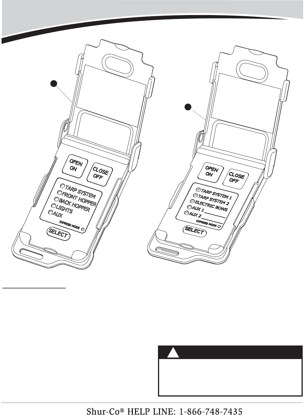
Wireless SMART1+™ Components
Item Part # Description
1. 1123160 SMART1+™ Replacement Transmitter (Agriculture/Grain Trailers)
2. 1123161 SMART1+™ Replacement Transmitter (Construction/Dump Bodies)
1
1
NOTICE
Do not power SMART1+™ or any Shur-Co® wire-
less system with battery charger alone, as this will
likely cause system abnormalities and/or system
malfunction. Instead, use a 12-volt truck/automobile
battery to provide power to trailer.
!
2
Wireless SMART1+™ Programming & Operating Instructions
P/N 1123159 Rev. A
2
The transmitter (remote) will power up when the lid is opened. The
remote will power down when the lid is closed or when the lid is
left open three minutes after the last button is pushed.
POWER UP/DOWN
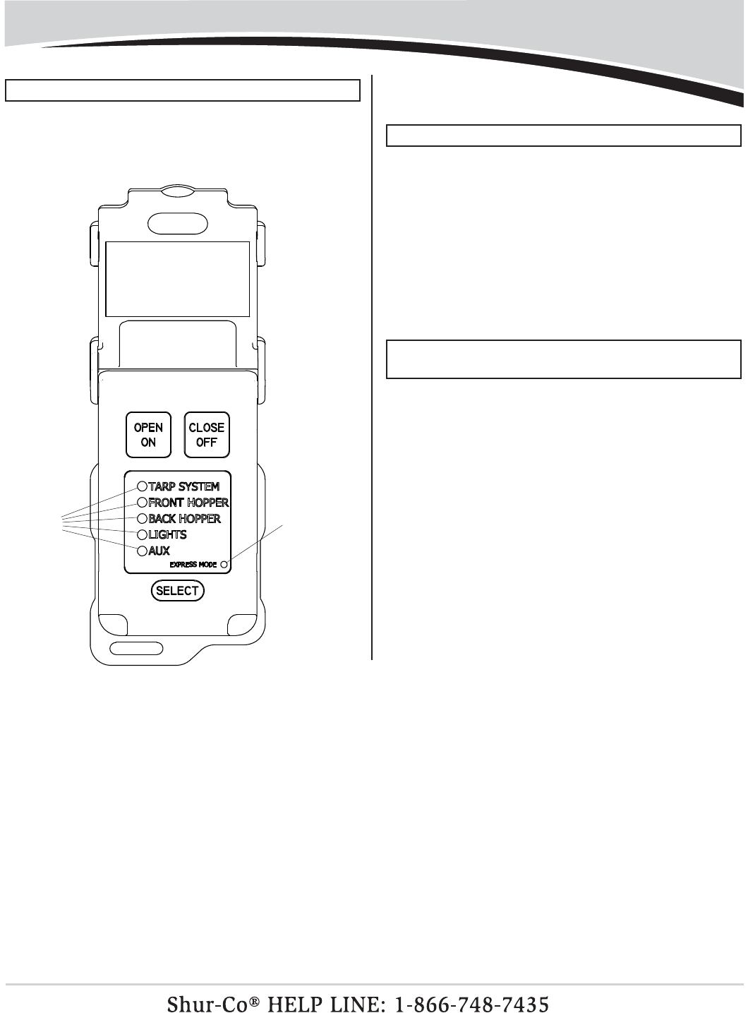
After power-up, the fi rst channel will be immediately active and
the indicator light for this channel will be fl ashing. The Open/On
and Close/Off buttons are operational for the indicated active
channel. While either the Open or Close button is pressed, the
indicator light for the active channel will fl ash faster, indicating a
command is being transmitted on the active channel.
The Select
button will cycle between enabled channels.
Each channel on the remote can be set to operate in either Mo-
mentary Mode or Express Mode.
STANDARD OPERATION
FLASHING
LIGHT
INDICATES
ACTIVE
CHANNEL
NOTE: See Channel Confi guration section for instructions on
how to set the operating mode for each channel.
Momentary mode: While the remote is in Momentary Mode, the
Open or Close button must be held while the system is operating.
The EXPRESS MODE indicator light will not be on when the
remote is in Momentary Mode.
Express mode: While the remote is in Express Mode, the Open
or Close button can be pressed and released. The system will
continue to operate until it is fully opened or closed. The system
can be stopped at any time by pressing any button on the remote,
or closing the remote lid.
The EXPRESS MODE indicator light will be on when the remote
is in Express Mode.
EXPRESS
MODE
INDICATOR
LIGHT

P/N 1123159 Rev.A
Wireless SMART1+™ Programming & Operating Instructions - continued
3
The receiver will accept and respond to signals from up to fi ve
remotes. The receiver will not respond to signals from remotes
that have not been paired to it.
NOTE: Only SMART1+™ remotes will function with
SMART1+™ receivers. The original SMARTtransmitter®
cannot be used.
PAIRING (INTRODUCING) REMOTE(S) TO RECEIVER
2. Check to be sure the receiver is connected to a 12-volt power
supply. The receiver must be connected to power to be pro-
grammed. If a battery disconnect switch is installed, make
sure it is turned on.
1. Remove the solenoid cover from the receiver assembly, pull-
ing gently on the cover to prevent damage to wires that are
connected to the cover.
Follow instructions below to pair remote(s) to receiver:
RED LED
LIGHT
PROGRAMMING
BUTTON
NOTE: Remotes are typically paired to their receivers at the
factory if a remote is shipped with a receiver.
Single SMART1+™ remote:
6a1. On the remote, press the Open/On button fi ve times. The
red light on the receiver will fl ash after each button press.
The red light will fl ash twice after receiving the last signal,
indicating it has been successfully programmed.
6a2. Verify that the remote and receiver are operating correctly,
then refasten the solenoid cover.
NOTE: Read the following steps in their entirety before
proceeding. Programing must be completed within 20
seconds.
The receiver will exit program mode after 20
seconds, whether o
r not it has received fi ve Open/On button
signals from the remote.
3. The receiver can learn to recognize up to fi ve remotes. Gather
all of the remotes to be introduced to the receiver. Open the
remote lid(s) to activate.
4. Set the remote(s) to the appropriate channel (Tarp System, Front
Hopper, etc.).
5. Press and hold the blue programming button on the receiver
for fi ve seconds. The red light will start fl ashing to indicate
that it is in programming mode. Release the programming
button. The red light will now turn off.
Multiple SMART1+™
remotes:
6b1. Press the Open/On button on the fi rst remote. The red light
will fl ash after receiving the signal.
6b2. Repeat the above step for each remote being used.
6b3. The receiver will accept up to fi ve signals. Press the Open/
On button additional times on the last remote being pro-
grammed to achieve a total of fi ve signals. The red light
on the receiver will fl ash twice after the last (fi fth) signal,
indicating it has been successfully programmed (see pro-
gramming example).
6b4. Verify that each remote and receiver are operating correctly,
then refasten the solenoid cover.
P/N 1123159 Rev. A
4
Programming & Operating Instructions - continued
Receiver programming example:
In this example, the receiver controls the front hopper motor. The
task is to program the hopper receiver to recognize three remotes.
1. Remove the solenoid cover and turn on the three remotes.
2.
Set all three remotes to the Front Hopper channel.
3.
Press and hold the blue programming button on the
receiver
for
fi ve seconds. The
red light on the receiver will fl ash
to indicate
it has entered Programming Mode. Release the programming
button. The light will now turn off.
4. Press the Open/On button on the fi rst remote. The red LED on
the receiver will fl ash to indicate that it has received a signal
and memory slot #1 has been fi lled.
5.
Press the
Open/On
button on the second remote. The
red
light on the receiver will fl ash
to indicate that is has received
a signal and memory slot #2 has been fi lled.
6. Press the Open/On button on the third remote. The red light
on the receiver will fl ash to indicate that it has received a
signal and memory slot #3 has been fi lled.
7.
Press the
Open/On
button on the third remote again. The
red
light on the receiver will fl ash
to indicate that it has received
a signal and memory slot #4 has been fi lled.
8. Press the Open/On button on the third remote again. The red
light will fl ash twice to indicate that it has received a signal
and memory slot #5 has been fi lled. The double fl ash also
indicates that the receiver has exited programming mode.
9.
Verify that the front hopper Open and Close operations are
functioning correctly on all three remotes.
Refasten the solenoid
cover to the motor assembly.
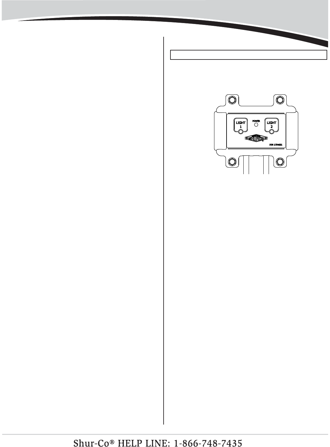
1. Be sure the LiteALL™ control module is connected to a 12-
volt power supply by checking that the green Power light on
the control module is on. If a battery disconnect switch is
installed, make sure it is turned on.
PROGRAM SMART1+™ REMOTE TO LITEALL™
2. To program the Light 1 output channel, hold the Light 1 but-
ton for fi ve seconds until the Power light turns off. The Light
1 indicator light should be on.
3.
Set the remote to the Lights channel indicator light by
pressing the Select button. A different channel on the re-
mote may be used, if desired.
Single SMART1+™ remote:
4a. Press the Open/On button fi ve times. After each button
press, the Light 1 channel indicator light will fl ash briefl y on
the LiteALL™ module.
Multiple SMART1+™ remotes:
4b.
Press the Open/On button at least one time for each remote.
After each transmission, the Light 1 channel indicator light
will fl ash briefl y on the LiteALL™ module. The LiteALL™ will
expect fi ve signals, so if you are programming less than fi ve
remotes, press the Open/On button additional times on the
last remote to take
up all fi ve memory slots in the LiteALL™
control module.
5. After the fi fth transmission, the Light 1 channel
indicator light
will fl ash twice to indicate that the remote(s) have been suc-
cessfully introduced to the LiteALL™ control module. The
Power light will then turn back on.
6. You can now operate the lights connected to the Lights 1
output channel with your SMART1+™ remotes.
7. To program the Light 2 output channel, repeat the instruc-
tions above using the Light 2 button on the LiteALL™ control
module. If you want the SMART1+™ remote(s) to control
both LiteALL™ output channels together with one button
press, make sure to select the same SMART1+™ channel
that was programmed to Light 1 in step 3.

P/N 1123159 Rev.A
Programming & Operating Instructions - continued
The Shur-Co® SMART1+™ remote has fi ve channels for control-
ling up to fi ve different devices. The channels can be confi gured
as follows:
• Unused channels can be disabled so they will be skipped when
Select button is pressed.
• The operating mode of each channel can be set to Momentary
Mode or Express Mode.
1. Hold the Select button down for 10 seconds and the remote
will enter Channel Confi guration Mode. The LED of the fi rst
channel will be lit solid on the remote. This indicates that the
fi rst channel is ready to be confi gured.
2. Set the operating mode of the channel. If the EXPRESS
MODE indicator light is lit solid, then the channel will operate
in EXPRESS MODE. If the EXPRESS MODE indicator light
is not on, the channel will operate in MOMENTARY MODE.
Press the Select button to toggle the operating mode to the
desired setting.
3. Enable or disable the channel. If the channel will be used and
paired with a receiver, press the Open/On button. If the chan-
nel will not be used, the channel can be disabled by pressing
the Close/Off button. The indicator light will automatically jump
to the next channel.
NOTE: If there is not at least one enabled channel after pro-
gramming, the remote will not save the changes and will re-
vert back to the previously saved channel settings.
TIP: To cancel changes and exit Channel Confi guration
Mode, close the remote cover.
NOTE: The remote will NOT activate any motor or lighting sys-
tem while the remote is in
Channel Confi guration Mode
.
CONFIGURING REMOTE CHANNELS
5
4. Repeat steps 2 and 3 for the remaining four channels.
5.
After confi guring the last channel, the channel status for all
fi ve channels will be displayed for three seconds. The channel
indicator lights of the enabled channels will be lit solid and the
channel indicator lights of the disabled channels will be off. The
remote will then automatically return to Operational Mode.
TO ACCESS BATTERY
UNFASTEN SCREW ON
BACK OF REMOTE WITH
PHILLIPS SCREW DRIVER
REPLACING BATTERIES
NOTE: Replacement batteries (P/N 1705163) may be
purchased from Shur-Co.
The SMART1+™ remote uses two AAA batteries. To access the
batteries, unfasten the center screw shown below and push cov
er in direction shown.
TO OPEN
COVER PUSH
IN DIRECTION
SHOWN

P/N 1123159 Rev. A
6
Troubleshooting Guide
Our Advanced Troubleshooting Guide is available on our website: http://www.shurco.com, or call our Help Line: 1-866-748-7435.
PROBLEM: TRY THIS:
The SMART1+™ remote is not
working.
None of the LED lights on the
remote are on.
1. Close the lid and open it again.
2. Make sure the batteries are placed correctly.
3. Replace both AAA batteries in the remote.
4. The remote may be damaged. Call Shur-Co’s Help Line.
The SMART1+™ remote is not
working.
I can operate the system with
the buttons on the trailer mount-
ed receiver box, but not with the
remote. The remote channel
light (next to Tarp System, for
example) is blinking, and when
I press the Open/On button, the
light blinks faster.
1.
Make sure the remote is set to the right channel. If you cannot set the remote to the
desired channel (Tarp System, for example) by pressing the Select button, the channel
must be enabled. See the Channel Enable/Disable section and enable the channel.
2. Reprogram the remote to the receiver and try again. See the Remote to Receiver
Programming section.
3.
Make sure you are within a few feet of the receiver and try again.
3a. If the system works at close range but not at greater distances, replace the AAA
batteries in the remote and try again.
3b. Make sure there are not metal objects placed between the remote and receiver.
Metal objects placed between the remote and receiver will reduce operating range.
4. Call Shur-Co’s Help Line.
The system will not operate with
the remote or with the buttons
on the trailer mounted receiver.
When the Open
or Close button
is pressed, I don’t hear
a loud
click from the receiver box.
1. Make sure the master disconnect switch on trailer (if equipped) is turned to the “ON”
position.
2. The circuit breaker may have tripped. Wait 15 seconds and try again.
3. Check for loose or corroded connections between the battery and the solenoid in the
receiver box.
4. Check for low system voltage. Measure the voltage between the positive and negative
posts on the solenoid in the receiver box on the trailer. The positive solenoid post is
marked “+” and the negative post is marked “-” at the base of the posts. With the truck
off, the voltage should measure between 12.5 and 12.7 volts. Make sure the voltage
reading is not negative, which indicates the power wires are hooked up backwards.
5. Press the programming button for about one second. The programming button is
located on the receiver module screwed to the inside of the grey receiver cover of
the receiver on the trailer. If the red light does not turn on while you are holding the
button, the module is not getting adequate voltage or the receiver may be damaged
Call Shur-Co’s Help Line.

P/N 1123159 Rev.A
7
PROBLEM: TRY THIS:
The system will not operate with
the remote or with the buttons
on the trailer-mounted receiver.
When the Open or Close button
is pressed, the solenoid in the
receiver box will click loudly (or
“chatter”) but the motor does not
turn.
1. Bypass the circuit breaker in the battery box and try again. If the problem goes away,
the breaker was fatigued or corroded and should be replaced.
2.
Ensure battery connections are tight and free of corrosion. Inspect all wires between
the batteries for corrosion. Verify battery voltage is between 12.5 and 12.7 volts with
truck off. Be sure to measure the voltage on the battery that the system is connected to.
3. Inspect dual-pole power connection at front of trailer. Replace if corrosion is present.
Disassemble the connector to inspect the set screws inside and make sure they are
tight, free of corrosion, and none of the wire strands are short-circuiting. Apply dielec-
tric grease (not black grease) to metal contacts.
4. Inspect wiring between dual-pole connector at front of trailer and solenoid in receiver
box. Replace corroded wires. Check wire for cuts in insulation. Copper wire will cor-
rode quickly if insulation is cut through.
5.
Disconnect the motor from the back two posts (marked IN and OUT) on the solenoid.
Press and hold the Open or Close button to engage the solenoid. If the solenoid does
not measure at least 12.5 or -12.5 volts between the back two posts while it is en-
gaged, the solenoid is damaged. Call Shur-Co’s Help Line.
6.
If the solenoid voltage measures at least 12.5 or -12.5 volts between the back two
posts (marked IN and OUT) when the motor wire is disconnected, the motor may be
damaged or there may be a short circuit in the motor wire between the motor and
solenoid. This assumes the system has been checked for corrosion and other issues
listed above. Call Shur-Co’s Help Line.
Our Advanced Troubleshooting Guide is available on our website: http://www.shurco.com, or call our Help Line: 1-866-748-7435.
Troubleshooting Guide - continued
NOTE: To quickly determine if the problem lies with the wiring between the battery and the solenoid, disconnect power from the
truck and then hook jumper cables from a vehicle directly to the solenoid. Hook the positive battery cable to the solenoid positive
post (marked +). Hook the negative battery cable to the solenoid negative post (marked -). If the system runs normally, the
problem is with the wiring that supplies power to the solenoid.

P/N 1123159 Rev. A
8
Safety and Compliance
Changes or modifi cations not expressly approved by the party
responsible for compliance could void the user's authority to op-
erate the equipment.
NOTE: This equipment has been tested and found to comply
with the limits for a Class B digital device, pursuant to part
15 of the FCC Rules. These limits are designed to provide
reasonable protection against harmful interference in a
residential installation. This equipment generates, uses and
can radiate radio frequency energy and, if not installed and
used in accordance with the instructions, may cause harmful
interference to radio communications. However, there is
no guarantee that interference will not occur in a particular
installation. If this equipment does cause harmful interference
to radio or television reception, which can be determined by
turning the equipment off and on, the user is encouraged to
try to correct the interference by one or more of the following
measures:
—Reorient or relocate the receiving antenna.
—Increase the separation between the equipment and re-
ceiver.
—Connect the equipment into an outlet on a circuit different
from that to which the receiver is connected.
—Consult the dealer or an experienced radio/TV technician
for help.
Son fonctionnement est soumis aux deux conditions suivantes:
(1) cet appareil ne peut pas provoquer d'interférences, et (2)
cet appareil doit accepter toute interférence, y compris celles
susceptibles de provoquer le fonctionnement du dispositif.
RADIO & TELEVISION INTERFERENCE
Operation is subject to the following two conditions: (1) This
device may not cause interference, and (2) this device must
accept any interference, including likely to cause operation of
the device.

P/N 1123159 Rev.A
9
Notes

P/N 1123159 Rev. A Notes
10
