Shure orporated AD1G57 Non-Broadcast Transmitter Worn on Body User Manual Exhibit D Users Manual per 2 1033 c3
Shure Incorporated Non-Broadcast Transmitter Worn on Body Exhibit D Users Manual per 2 1033 c3
Exhibit D Users Manual per 2 1033 c3
© 2016 Shure Incorporated
27A (Rev. 1)
AD1 TRANSMITTER
USER GUIDE
AXIENT DIGITAL
Printed in China
DRAFT 9.1.16

Important Product Information
LICENSING INFORMATION
Licensing: A ministerial license to operate this equipment may be required in certain areas. Consult your national authority for possible requirements.
Changes or modifications not expressly approved by Shure Incorporated could void your authority to operate the equipment. Licensing of Shure wireless
microphone equipment is the user’s responsibility, and licensability depends on the user’s classification and application, and on the selected frequency.
Shure strongly urges the user to contact the appropriate telecommunications authority concerning proper licensing, and before choosing and ordering
frequencies.
Information to the user
This equipment has been tested and found to comply with the limits for a Class B digital device, pursuant to Part 15 of the FCC Rules. These limits are
designed to provide reasonable protection against harmful interference in a residential installation. This equipment generates uses and can radiate radio
frequency energy and, if not installed and used in accordance with the instructions, may cause harmful interference to radio communications. However,
there is no guarantee that interference will not occur in a particular installation. If this equipment does cause harmful interference to radio or television
reception, which can be determined by turning the equipment off and on, the user is encouraged to try to correct the interference by one or more of the
following measures:
• Reorient or relocate the receiving antenna.
• Increase the separation between the equipment and the receiver.
• Connect the equipment to an outlet on a circuit different from that to which the receiver is connected.
• Consult the dealer or an experienced radio/TV technician for help.
Note: EMC conformance testing is based on the use of supplied and recommended cable types. The use of other cable types may degrade EMC
performance.
Please follow your regional recycling scheme for batteries, packaging, and electronic waste.
This device complies with Industry Canada licence-exempt RSS standard(s). Operation of this device is subject to the following two conditions: (1) this
device may not cause interference, and (2) this device must accept any interference, including interference that may cause undesired operation of the
device.
Le présent appareil est conforme aux CNR d'Industrie Canada applicables aux appareils radio exempts de licence. L'exploitation est autorisée aux deux
conditions suivantes : (1) l'appareil ne doit pas produire de brouillage, et (2) l'utilisateur de l'appareil doit accepter tout brouillage radioélectrique subi,
même si le brouillage est susceptible d'en compromettre le fonctionnement.
WARNING: Danger of explosion if battery incorrectly replaced. Operate only with Shure compatible batteries.
Note: Use only with the included power supply or a Shure-approved equivalent.
WARNING
• Battery packs may explode or release toxic materials. Risk of fire or burns. Do not open, crush, modify, disassemble, heat above 140°F (60°C), or
incinerate.
• Follow instructions from manufacturer
• Only use Shure charger to recharge Shure rechargeable batteries
• WARNING: Danger of explosion if battery incorrectly replaced. Replace only with same or equivalent type.
• Never put batteries in mouth. If swallowed, contact your physician or local poison control center
• Do not short circuit; may cause burns or catch fire
• Do not charge or use battery packs other than Shure rechargeable batteries
• Dispose of battery packs properly. Check with local vendor for proper disposal of used battery packs.
• Batteries (battery pack or batteries installed) shall not be exposed to excessive heat such as sunshine, fire or the like
Australia Warning for Wireless
This device operates under an ACMA class licence and must comply with all the conditions of that licence including operating frequencies. Before 31
December 2014, this device will comply if it is operated in the 520-820 MHz frequency band. WARNING: After 31 December 2014, in order to comply,
this device must not be operated in the 694-820 MHz band.
DRAFT 9.1.16

AD1 Axient Digital Bodypack Transmitter
The AD1 transmitter delivers superior audio performance in a compact, lightweight package. Efficient, ultra-linear RF performance maximizes the num-
ber of channels on-air in crowded RF environments. Advanced power management provides extended, rechargeable battery life and highly accurate
status metering.
Features
• All-digital signal path delivers superior audio clarity and quality
• Ultra-linear RF performance places more channels on-air
• IR Sync function automatically tunes transmitter to the receiver frequency
• Shure lithium-ion rechargeable battery delivers up to 8 hours of runtime from a single charge
• Advanced control menu to adjust frequency and audio settings from the transmitter
• Lockable user interface prevents accidental or inadvertent changes to controls once settings are made
• Compatible with all Shure wireless microphones that have a TA4F connector.
• LEMO connector model available for use with LEMO connector microphones
Included Components
Bodypack rechargeable lithium-ion battery (2)
Dual-band flexible antenna
Threaded TAF4 adapter WA340
Transmitter carrying case WA610
Zipper bag 26A13
Belt clip 44A12547
Optional Accessories
Bodypack rechargeable lithium-ion battery AXT910
Y-Cable for bodypack transmitters AXT652
LEMO Y-cable for bodypack transmitters AXT652LEMO3
Dual-band flexible antenna AXT642
Portable bodypack charging station AXT903
3-AA Battery Sled for AXT100 bodypack
transmitter
AXT913
Instrument cable WA302
Replacement belt clip 44A12547
Instrument cable with right angle 1/4" connector WA304
Mute Switch for Bodypack WA661
Mute Switch for 2 Bodypacks WA662
DRAFT 9.1.16
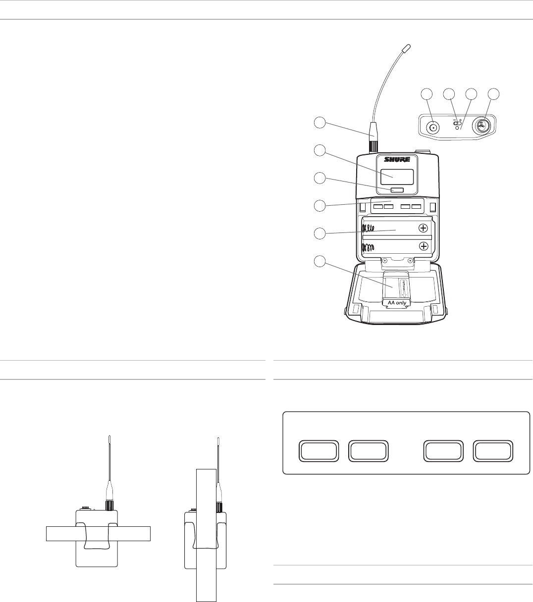
AD1 Transmitter Overview
1
7 8 9 10
2
3
4
5
6
① RF Antenna
For RF signal transmission.
② Display:
View menu screens and settings. Press any control button to activate
the backlight.
③ Infrared (IR) Port
Align with the receiver IR port during an IR Sync for automated
transmitter programming.
④ Control Buttons
Use to navigate through parameter menus and change values.
⑤ Battery Compartment
Requires Shure SB900 rechargeable battery or 2 AA batteries.
⑥ AA Battery Adapter
Remove to accommodate a Shure SB900 battery
⑦ SMA Connector
Connection point for RF antenna.
⑧ On/Off Switch
Powers the unit on or off.
⑨ Power LED
- Green = unit is powered on
- Red = low battery or battery error (see Troubleshooting), Mute Mode enabled
⑩ Input Jack
- Connects to a 4-Pin Mini Connector (TA4F) microphone or instrument cable.
- Connects to a LEMO connector
Wearing the Bodypack Transmitter
Clip the transmitter to a belt or slide a guitar strap through the transmitter
clip as shown.
For best results, the belt should be pressed against the base of the clip.
Transmitter Controls
Use to navigate through parameter menus and change values.
exit enter
^
^
exit Acts as a 'back' button to return to previous menus or pa-
rameters without confirming a value change
enter Enters menu screens and confirms parameter changes
∨∧ Use to scroll through menu screens and to change param-
eter values
Locking the Controls
Lock transmitter controls to prevent accidental or unauthorized changes to
parameters. The lock icon is shown on the home screen when the control
lock in enabled.
1. From the Utilities menu, navigate to Lock
and selection one of the following:
- Yes: Locks the controls
- No: Unlocks the controls
2. Press enter to save.
To quickly unlock a transmitter: Press enter, select Yes, and press
enter.
DRAFT 9.1.16
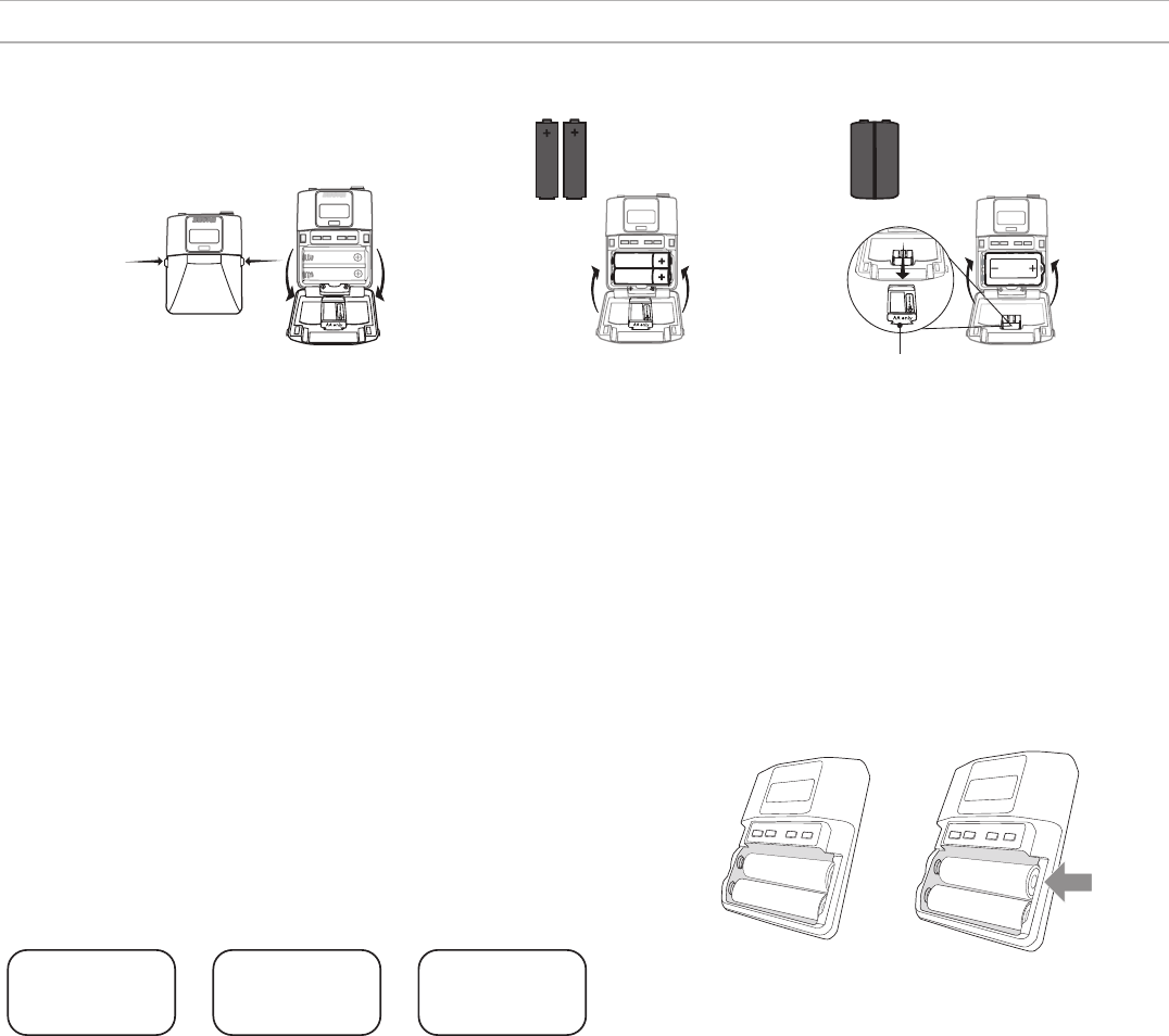
Setting the AA Battery Type
To ensure accurate display of transmitter runtime, set the battery type in
the transmitter menu to match the installed AA battery type. If a Shure
SB900 rechargeable battery is installed, selecting a battery type is not
necessary and the battery type menu will not be displayed.
1. Press the menu button to navigate to the battery icon.
2. Use the ▼▲ buttons to select the installed battery type:
- AL = Alkaline
- nH = Nickel Metal Hydride
- Li = Lithium Primary
3. Press enter to save.
Battery Info
Chem: Alkaline
Battery Info
Chem: NiMH
Battery Info
Chem: Lithium
Battery Installation
ULXD1
ULXD1
AA SB900
65A15224
① Accessing the Battery Compartment
Press the side tabs on the bodypack or unscrew the cover on the handheld as shown to access the battery compartment.
② Installing Batteries
- AA Batteries: Place batteries (note polarity markings) and AA Adaptor as shown
- Shure SB900 Battery: Place battery as shown (note polarity markings), remove AA Adaptor from bodypack transmitter, stow AA Adaptor in door for handheld
transmitter
Note: If using AA batteries, set the battery type using the transmitter menu.
AA Battery Installation
Fully insert the batteries as shown to ensure proper battery contact
and to allow the door to latch securely.
Correct Incorrect
DRAFT 9.1.16

Shure SB900 Rechargeable Battery
Shure SB900 lithium-ion batteries offer a rechargeable option for powering the transmitters. Batteries quickly charge to 50% capacity in one hour and
reach full charge within three hours.
Single chargers and multiple bay chargers are available to recharge the Shure batteries.
Caution: Only charge Shure rechargeable batteries with a Shure battery charger.
Shure SB900 Runtime
1 mW 10 mW 20 mW
>11
hours
>11
hours
>7 hour
Checking Battery Info
When using an SB900 rechargeable battery, the receiver and transmitter home screens display the number of hours and minutes remaining.
Detailed information for the SB900 is displayed in the receiver Batt Info menu and the transmitter menu: Utilities > Batt Info
• Time: Battery runtime
• Health: Percentage of current battery health
• Charge: Percentage of change
• Cycles: Record of the number of charging cycles for the installed battery
• Temp: Battery temperature in Fahrenheit and Celsius
• mAh: Remaining mAh for the installed battery
Important Tips for Care and Storage of Shure Rechargeable Batteries
Proper care and storage of Shure batteries results in reliable performance and ensures a long lifetime.
• Always store batteries and transmitters at room temperature
• Ideally, batteries should be charged to approximately 40% of capacity for long-term storage
• During storage, check batteries every 6 months and recharge to 40% of capacity as needed
For additional rechargeable battery information, visit www.shure.com.
AA Batteries and Transmitter Runtime
Transmitters are compatible with the following AA battery types:
• Alkaline
• Nickel Metal Hydride (NiMH)
• Lithium Primary
A 5-segment battery indicator representing the charge level of the transmitter battery is displayed on the screens of the transmitter and receiver. The fol-
lowing tables contain the approximate remaining transmitter runtime in hours:minutes.
Alkaline Batteries: Up to 9
Hours of Runtime
Battery
Indicator
Approximate
Runtime Remaining
(hours:minutes)
9:30 to 7:30
7:30 to 5:30
5:30 to 3:30
3:30 to 2:30
2:30 to 1:30
< 0:30
NiMH Batteries: Up to 10
Hours of Runtime
Battery
Indicator
Approximate
Runtime Remaining
(hours:minutes)
10:00 to 8:00
8:00 to 6:00
6:00 to 4:00
4:00 to 2:00
2:00 to 0:20
0:20 to 0:00
Lithium Primary Batteries:
Up to 16 Hours of Runtime
Battery
Indicator
Approximate
Runtime Remaining
(hours:minutes)
16:00 to 12:45
12:45 to 9:30
9:30 to 6:30
6:30 to 3:15
3:15 to 0:20
0:20 to 0:00
DRAFT 9.1.16

Main Menu Parameters
The Main Menu organizes the available transmitter parameters into three categories:
• Radio
• Audio
• Utilities
To change a parameter, press the enter button to enable editing and use the arrow buttons to change values or settings. When finished, press enter to
save.
Radio Menu
Group and Channel
Press the enter button to enable
editing of a group (G:) or channel
(C:). Use the arrow buttons to
adjust the values.
Frequency
Press the enter button once to
edit the first 3 digits, or twice to
edit the second 3 digits.
RF Power
Higher power settings can extend
the range of the transmitter.
RF Output
- On: RF signal is active
- Mute: RF signal is inactive
Audio Menu
MicOfs
Adjust Mic Offset level to balance mic levels when using
two bodypacks for frequency diversity.
Pad
Adjust the pad to avoid overloading the audio input.
PolarityPos
Selectable polarity assignment for LEMO connector
transmitters:
- Pos: Positive pressure on microphone diaphragm produces posi-
tive voltage on pin 2 (with respect to pin 3 of XLR output) and the
tip of the TRS output.
- Neg: Positive pressure on microphone diaphragm produces neg-
ative voltage on pin 2 (with respect to pin 3 of XLR output) and
the tip of the TRS output.
MuteMode
When enabled, the power switch is configured as a mute
switch for the audio:
- Power switch on: audio signal on
- Power switch off: audio signal muted
Tone
Transmitter will generate a continuous test tone. The tone
can be set to 400 Hz or 1000 Hz.
Level
When enabled, allows for adjustment of the output level of
the test tone.
Utilities Menu
Device ID
Assign a device ID of up to 9 letters
or numbers.
Lock
Locks the transmitter controls and
power switch.
Drop Mark
When enabled, press the enter
button to drop a marker in Wireless
Workbench or Shure ChannelsPlus.
Versions
Displays transmitter information:
- FW: Installed firmware
- HW: Hardware version
- SN: Serial number
Batt Info
Displays battery information:
- Time: Battery runtime
- Health: Percentage of current battery
health
- Charge: Percentage of change
- Cycles: Record of the number of
charging cycles for the installed battery
- Temp: Battery temperature in
Fahrenheit and Celsius
- mAh: Remaining mAh for the installed
battery
Reset All
Restores all transmitter parameters
to factory settings.
Tips for Editing Menu Parameters
• To access the menu options from the home screen, press the menu button. Each additional press of the menu button advances to the next menu
screen.
• A menu parameter will blink when editing is enabled
• To increase, decrease or change a parameter, use the arrow buttons
• To save a menu change, press enter
• To exit a menu without saving a change, press menu
DRAFT 9.1.16

Scan and Sync
Use this procedure to tune a receiver and transmitter to the best open channel.
Important! Before you begin:
Turn off all transmitters for the systems you are setting up. (This prevents them from interfering with the frequency scan.)
Turn on the following potential sources of interference so they are operating as they would be during the presentation or performance (the scan will de-
tect and avoid any interference they generate).
• Other wireless systems or devices
• Computers
• CD players
• Large LED panels
• Effects processors
1. Press the channel number button to select a receiver channel.
2. Power on the transmitter.
3. Press the sync button on the receiver.
4. Align the IR windows until the receiver IR port illuminates red.
Note: When complete, SyncSuccess! appears. The transmitter and receiver are now tuned to the same frequency.
Linking Two Transmitters to a Receiver
Linking two transmitters to a receiver offers the flexibility to provide a performer with either a handheld or bodypack transmitter to meet their preference.
For performances requiring instrument changes, two bodypack transmitters can be linked to a single receiver.
Note: Only turn on and operate one transmitter at a time to prevent interference between the transmitters.
Syncing the Transmitters to the Receiver
Both transmitters must be individually linked to the receiver by performing an IR Sync.
1. Turn on the first transmitter and perform an IR Sync with the receiver.
2. Perform a sound check and adjust the transmitter gain if necessary. When finished, turn off the transmitter.
3. Turn on the second transmitter and perform an IR Sync with the receiver.
4. Test the transmitter at performance conditions and adjust the transmitter gain if necessary. When finished, turn off the transmitter.
Matching Audio Levels with Mic Offset
When linking two transmitters to a receiver, there may be a difference in volume levels between microphones or instruments. If this occurs, use the
MicOfs function to match the audio levels and eliminate audible volume differences between transmitters. If using a single transmitter, set MicOfs to 0 dB.
1. Turn on the first transmitter and perform a sound check to test the audio level. Turn off the transmitter when finished.
2. Turn on the second transmitter and perform a sound check to test the audio level.
3. If there is an audible difference in the sound level between the transmitters, navigate to the MicOfs menu on
the transmitter to increase or decrease the Mic Offset in realtime to match the audio levels.
Tx Overload
The Tx Overload message is displayed when the audio input of the
transmitter experiences an overload.
RF Mute
RF Mute prevents transmission of the audio by suppressing the RF sig-
nal, while allowing the transmitter to remain powered-on. The message
RF Mute is shown on the home screen.
RADIO
RF Output: Mute
1. From the Radio menu, navigate to RF Output.
2. Choose one of the following options:
- On: RF signal is active
- Mute: RF signal is disabled
3. Press enter to save.
Turning the transmitter off and on, or replacing the battery will restore
RF Output to On.
Power-on RF Mute
Power-on RF Mute places the transmitter in RF Mute mode immediately
when turned on.
• Starting with the transmitter off, press and hold the exit button, and
then switch on the power
• Continue to hold the exit button until the RF Muted message appears
on the home screen
DRAFT 9.1.16

Updating Firmware
Firmware is embedded software in each component that controls functionality. Periodically, new versions of firmware are developed to incorporate
additional features and enhancements. To take advantage of design improvements, new versions of the firmware can be uploaded and installed using
the Firmware Update Manager tool available in Shure's Wireless Workbench® 6 (WWB6) software. Software is available for download from http://www.
shure.com/wwb.
Firmware Versioning
When updating receiver firmware, update transmitters to the same firmware version to ensure consistent operation.
The firmware of all ULX-D devices has the form of MAJOR.MINOR.PATCH (e.g., 1.2.14). At a minimum, all devices on the network (including transmit-
ters), must have the same MAJOR and MINOR firmware version numbers (e.g., 1.2.x).
Updating the Transmitter
1. To upload the firmware to the transmitter, go to Device Conguration > Tx Firmware Update on the receiver.
2. Place the transmitter on its side and align the IR ports.
3. Press ENTER on the receiver to begin the download to the transmitter. IR ports must be
aligned for the entire download, which can take 50 seconds or longer.
Specifications
AD1 Bodypack Transmitter
RF Carrier Frequency Range
470–814 MHz
Note: varies by region
Working Range
Under typical conditions 150 m (500 ft)
Line of Sight, outdoors for a single
system
500 m (1600 ft)
Note: Actual range depends on RF signal absorption, reflection and interference.
Audio Frequency Response
40 Hz – 18 kHz (+1, -3 dB)
Note: Dependent on microphone type
RF Tuning Step Size
25 kHz
Modulation
45 kHz max. deviation
FM, Audio Reference Companding with pre- and de-emphasis
Signal-to-Noise Ratio
A-weighted, 1% THD, referenced at 0 dB setting on transmitter
>113 dB
Total Harmonic Distortion
45 kHz max. deviation
<0.3%, A-weighted, typical
System Audio Polarity
Positive pressure on microphone diaphragm (or positive voltage applied to tip of WA302
phone plug) produces positive voltage on pin 2 (with respect to pin 3 of low-impedance
output) and the tip of the high impedance 1/4-inch output.
Gain Adjustment Range
-10 to +40 dB (in 1 dB steps)
Battery Type
Shure AXT910 (Rechargeable Li-Ion)
Battery Life
Up to 8 hours (low power mode)
Dimensions
77 mm x 66 mm x 17 mm (3.0 in. x 2.6 in. x 0.7 in.) H x W x D, XXXXERROR: [[ with
SB900 battery ]] DOES NOT EXISTXXXX
Weight
146.6 g (5.2 oz.), with batteries
Housing
Cast aluminum
Operating Temperature Range
-18°C (0°F) to 63°C (145°F)
Note: Battery characteristics may limit this range.
Storage Temperature Range
-29°C (-20°F) to 74°C (165°F)
Note: Battery characteristics may limit this range.
Audio Input
Connector
4-Pin male mini connector (TA4M) / 3-Pin male mini connector (LEMO)
Configuration
Unbalanced
Impedance
1 MΩ
Maximum Input Level
1 kHz at 1% THD
Input Gain Setting −10 to +9 dB 12.5 dBu
+10 to +19 dB −2.5 dBu
+20 to +40 dB −7.5 dBu
RF Output
Connector
SMA (UHF and ShowLink); Shell=Ground, Center=Signal
Antenna Type
AXT642 Bodypack Dual Band Antenna (integrated helical and 1/4 wave)
Power
See Frequency Range and Output Power table
Impedance
50 Ω
DRAFT 9.1.16

Frequency Bands and Transmitter RF Power
Band Frequency Range
(MHz) RF Power (mW)
G1 470 to 530 10/100
G1E 470 to 530 10/50
G7C 470 to 510 10/50
G12 479 to 530 10/20
G19 470 to 530 2/10
H4 518 to 578 10/100
H4E 518 to 578 10/50
H12 518 to 565 10/20
H18 518 to 578 2/10
J5 578 to 638 10/100
J5E 578 to 638 10/50
J5HK 578 to 638 10
J12 578 to 638 2/10
K4E 606 to 666 10/50
L3 638 to 698 10/100
L3E 638 to 698 10/50
L20 638 to 698 2/10
M8 666 to 730 10/50
MA24 779 to 806 10
MJBX 806 to 810 10
P8 710 to 790 10/50
P9 710 to 787 10/50
Q5 740 to 814 10/50
R16 794 to 806 10/50
DRAFT 9.1.16
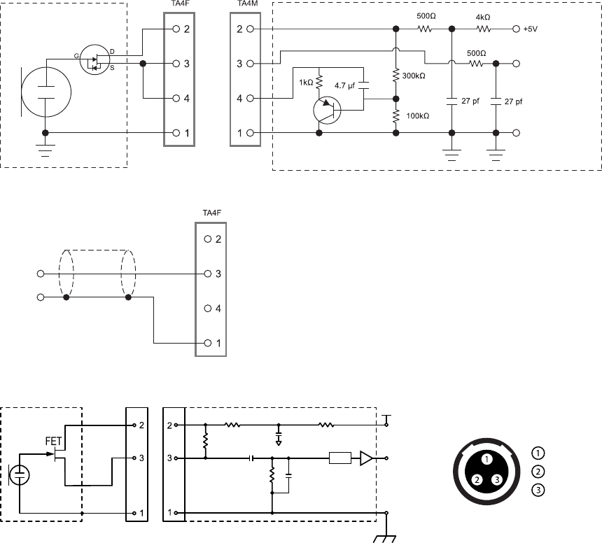
Input Connector Diagrams
TA4M
LEMO
SHIELD
.
N
100 µF
12 dB
440 pF
Ground
5 V DC
Ground
Bias Voltage
Audio Input
Audio Input
1µF
Pad
DRAFT 9.1.16

Certifications
Meets essential requirements of the following European Directives:
• R&TTE Directive 99/5/EC
• WEEE Directive 2002/96/EC, as amended by 2008/34/EC
• RoHS Directive 2002/95/EC, as amended by 2008/35/EC
Note: Please follow your regional recycling scheme for batteries and electronic waste
Meets requirements of the following standards: EN 300 328, EN 300 422 Parts 1 and 2, EN 301 489 Parts 1 and 9, EN60065.
Certified under FCC Part 15 and FCC Part 74.
Certified in Canada by IC to RSS-123 and RSS-210.
Industry Canada ICES-003 Compliance Label: CAN ICES-3 (B)/NMB-3(B)
This radio transmitter has been approved by Industry Canada to operate with the antenna types listed below with the maximum permissible gain and required an-
tenna impedance for each antenna type indicated. Antenna types not included in this list, having a gain greater than the maximum gain indicated for that type, are
strictly prohibited for use with this device.
FCC ID: DD4AD1A, DD4AD1B, DD4AD1C, DD4AD1D. IC: 616A-AD1A, 616A-AD1C, 616A-AD1D.
This device complies with Industry Canada licence-exempt RSS standard(s). Operation of this device is subject to the following two conditions: (1) this device may
not cause interference, and (2) this device must accept any interference, including interference that may cause undesired operation of the device. Le présent appa-
reil est conforme aux CNR d'Industrie Canada applicables aux appareils radio exempts de licence. L'exploitation est autorisée aux deux conditions suivantes : (1)
l'appareil ne doit pas produire de brouillage, et (2) l'utilisateur de l'appareil doit accepter tout brouillage radioélectrique subi, même si le brouillage est susceptible
d'en compromettre le fonctionnement.
The CE Declaration of Conformity can be obtained from Shure Incorporated or any of its European representatives. For contact information please visit www.shure.
com
The CE Declaration of Conformity can be obtained from: www.shure.com/europe/compliance
Authorized European representative:
Shure Europe GmbH
Headquarters Europe, Middle East & Africa
Department: EMEA Approval
Jakob-Dieffenbacher-Str. 12
75031 Eppingen, Germany
Phone: 49-7262-92 49 0
Fax: 49-7262-92 49 11 4
Email: info@shure.de
LICENSING INFORMATION
Licensing: A ministerial license to operate this equipment may be required in certain areas. Consult your national authority for possible requirements. Changes or
modifications not expressly approved by Shure Incorporated could void your authority to operate the equipment. Licensing of Shure wireless microphone equipment
is the user’s responsibility, and licensability depends on the user’s classification and application, and on the selected frequency. Shure strongly urges the user to
contact the appropriate telecommunications authority concerning proper licensing, and before choosing and ordering frequencies.
Information to the user
This equipment has been tested and found to comply with the limits for a Class B digital device, pursuant to Part 15 of the FCC Rules. These limits are designed to
provide reasonable protection against harmful interference in a residential installation. This equipment generates uses and can radiate radio frequency energy and,
if not installed and used in accordance with the instructions, may cause harmful interference to radio communications. However, there is no guarantee that interfer-
ence will not occur in a particular installation. If this equipment does cause harmful interference to radio or television reception, which can be determined by turning
the equipment off and on, the user is encouraged to try to correct the interference by one or more of the following measures:
• Reorient or relocate the receiving antenna.
• Increase the separation between the equipment and the receiver.
• Connect the equipment to an outlet on a circuit different from that to which the receiver is connected.
• Consult the dealer or an experienced radio/TV technician for help.
Australia Warning for Wireless
This device operates under an ACMA class licence and must comply with all the conditions of that licence including operating frequencies. Before 31 December
2014, this device will comply if it is operated in the 520-820 MHz frequency band. WARNING: After 31 December 2014, in order to comply, this device must not be
operated in the 694-820 MHz band.
AD1
Certified under FCC Part 74.
Certified by IC in Canada under RSS-123 and RSS-102.
IC: 616A-AD1 G50, 616A-AD1 H50, 616A-AD1 J50, 616A-AD1 L50; 616A-AD1.
FCC: DD4AD1G50, DD4AD1H50, DD4AD1J50, DD4AD1L50.
DRAFT 9.1.16