Shuttle PN20 11g module User Manual
Shuttle Inc. 11g module
UserManual.wiki
>
Shuttle
>
PN20 User Manual
>
User manual
Contents
1.
OEM installation guide
2.
User manual
User manual
Navigation menu
Upload a User Manual
Namespaces
Wiki Guide
HTML
PDF
Info
Views
User Manual
Discussion / Help
Navigation
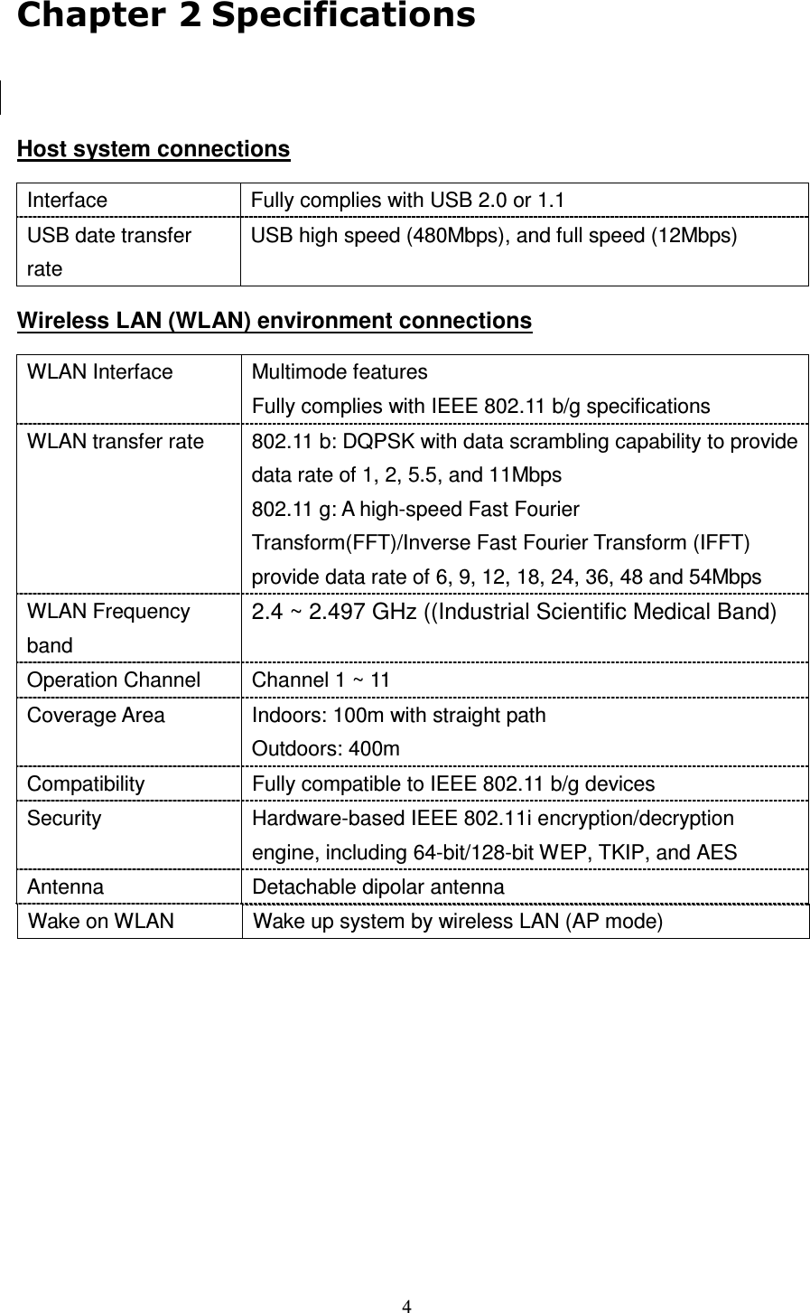

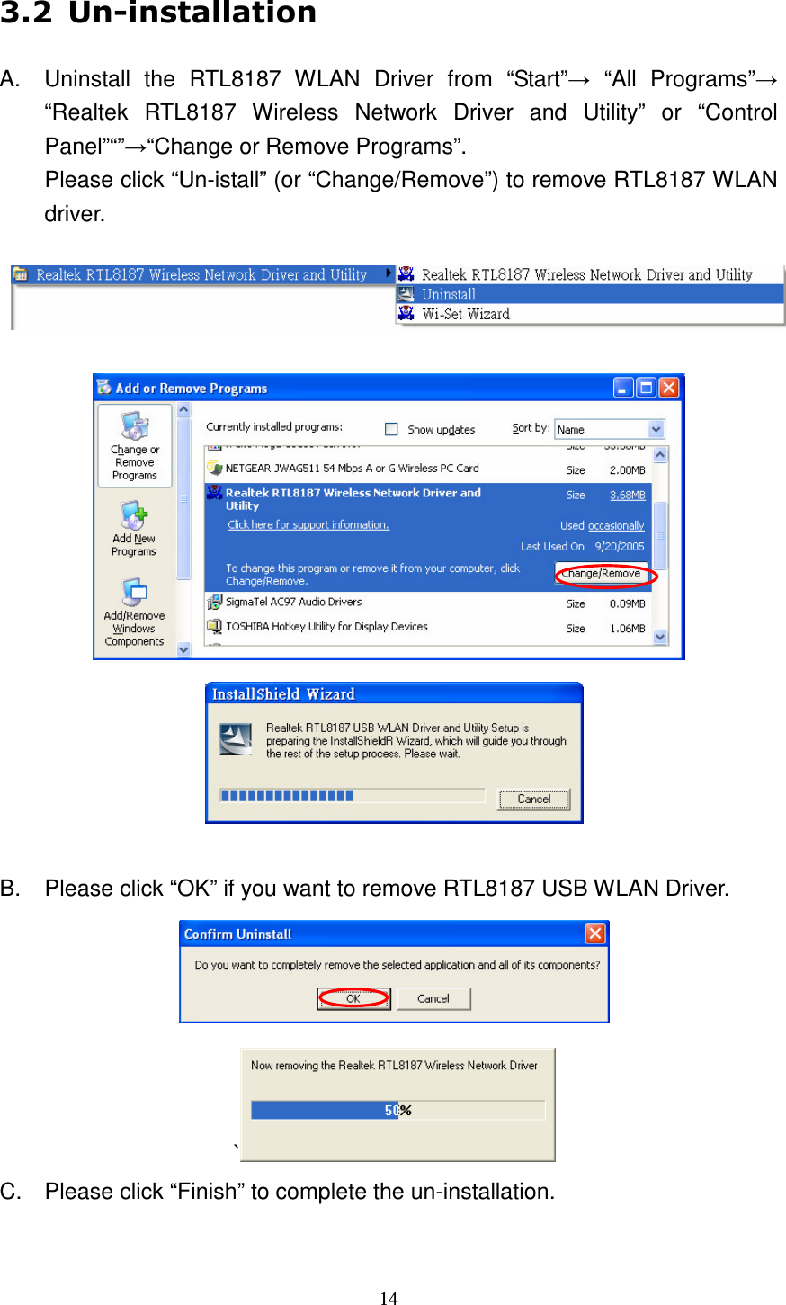
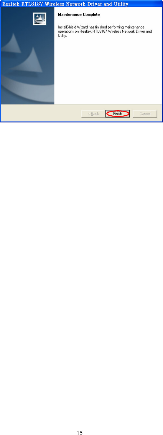
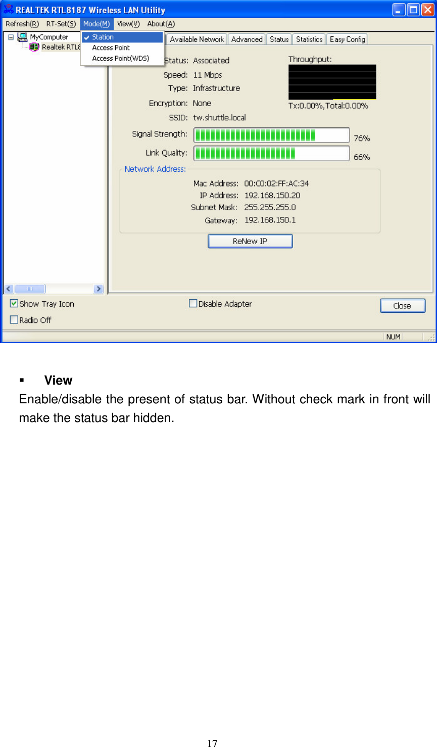
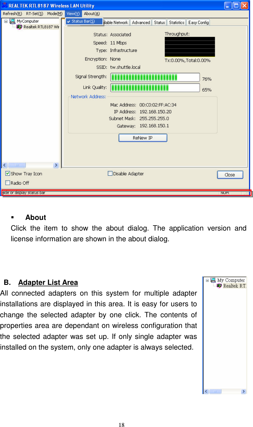
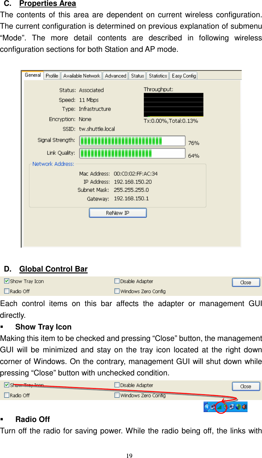
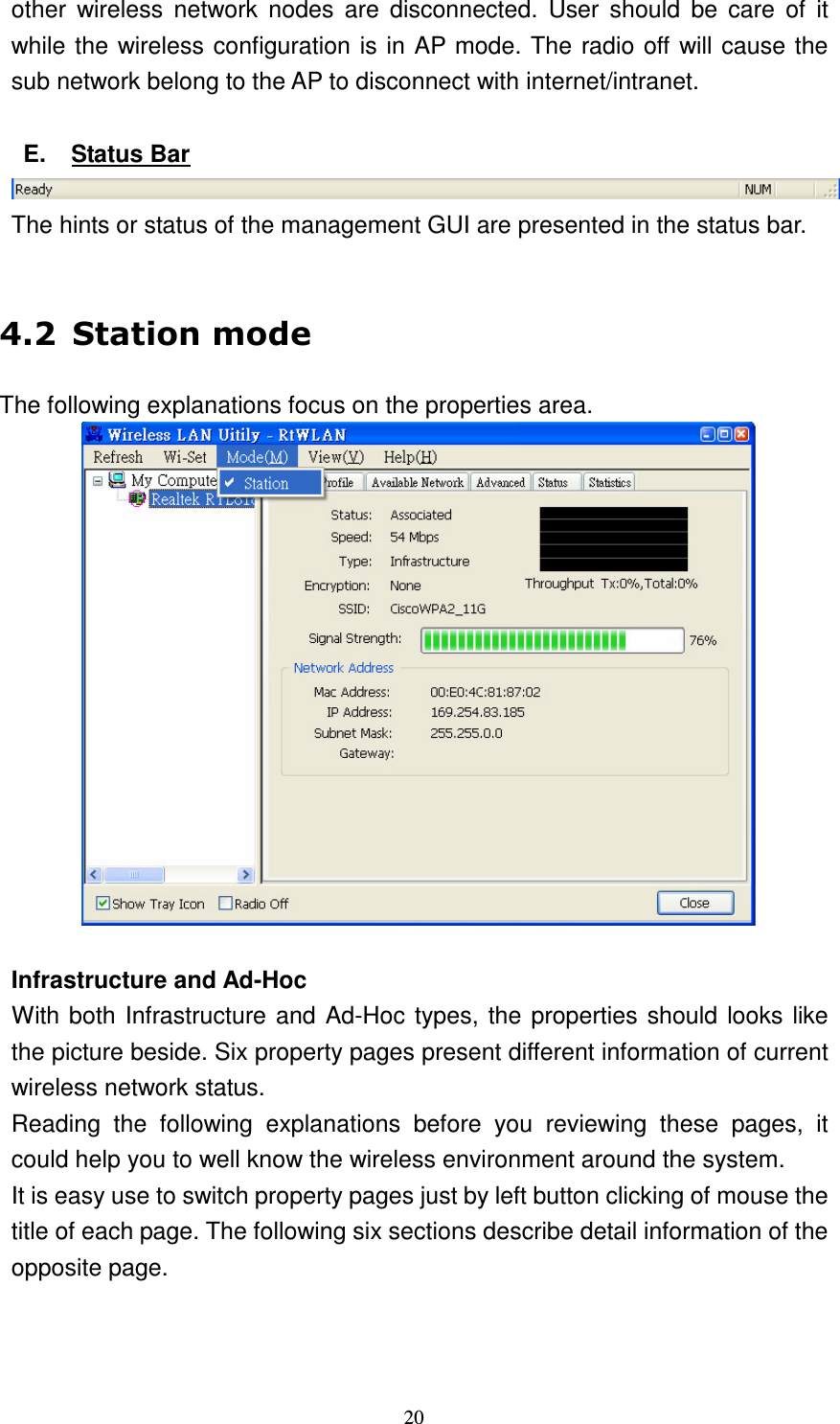
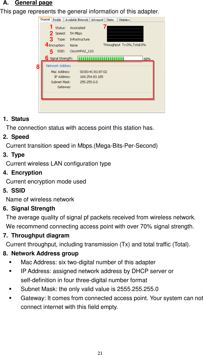
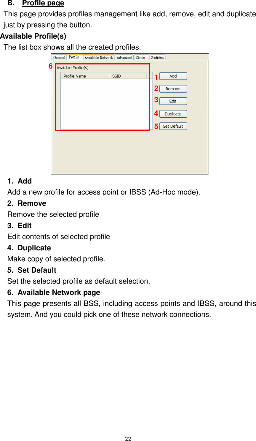
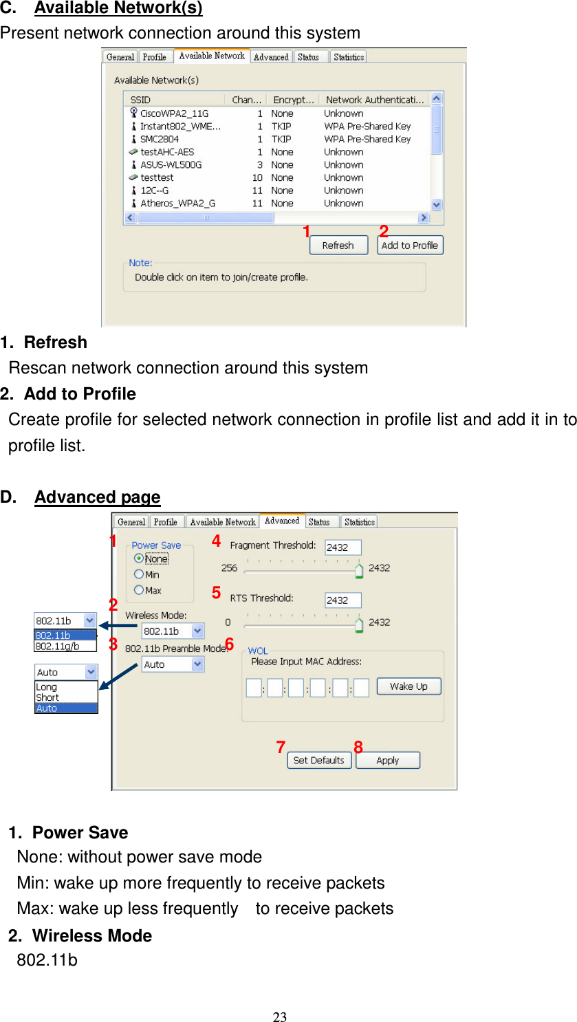
![16 " #$%&'()" & A. Main Menu The main menu includes five submenus. Refresh As clicking the refresh menu, we can update and re-enumerate the contents of adapter list area. RT-Set Mode Wireless configuration was quickly switched to be either [Station] or [Access Point] or [Access Point(WDS)]. A. Main Menu B. Adapter List Area C. Property Area D. Global Control Bar E. Status Bar](https://usermanual.wiki/Shuttle/PN20.User-manual/User-Guide-855053-Page-16.png)