Contents
- 1. OEM installation guide
- 2. User manual
User manual
PN20
Shuttle Wireless Kit
Realtek RTL8187
User Guide
2
Content
Chapter 1 Introduction ..................................................................................3
Chapter 2 Specifications ...............................................................................4
Chapter 3 Installation/ Un-installation..........................................................5
3.1 Installation.........................................................................................5
3.1.1 For Window XP and Windows 2000 user................................5
3.1.2 For Windows Vista user...........................................................9
3.2 Un-installation.................................................................................14
Chapter 4 Wireless LAN Management GUI ................................................16
4.1 Introduction of Main Window.........................................................16
4.2 Station mode ...................................................................................20
3
Thank you for purchasing Realtek RTL8187 Wireless LAN USB 2.0 Adapter.
Realtek RTL8187 Wireless LAN USB 2.0 Adapter is another perfect
combination of both performance and cost-effective product introduced by
Realtek. Realtek hopes you can enjoy the wireless world through this solid
profiled wireless card.
RTL8187 provides a full solution of all the IEEE 802.11 b/g protocols. Both of
our solutions passed the WIFI tests and will be compatible with all the wireless
products with WIFI logo. If you have a Realtek RTL8187 Wireless LAN USB
2.0 Adapter on hand, it means you can connect to the wireless world without
any difficulty.
RTL8187 provides all the data rates in the IEEE 802.11 b/g standards.
RTL8187 supports both the short and long preambles to ensure the
compatibility of legacy wireless products and new ones, saving the panic
works for end users to find compatible products.
Since the security has became one of the most important issue in the wireless
society, Realtek provides you with the full security coverage from the naïve
64/128bits Wep encryptions, second generation WPA-PSK encryption, to the
most advanced WPA2-AES encryption. WPA2 is the latest security standard
currently approved by WIFI standard. Realtek cares about your security on the
wireless world and makes our efforts to protect our users from malicious
sniffers.
Saving mode, Adhoc wireless Lan, Wake on Lan(WOL) and other exciting
features are also included in this Realtek RTL8187 Wireless LAN USB 2.0
Adapter. We will guild you through these exciting features in the following
chapters and we believe that you will have a great satisfactory with its
performance and ease of use.

4
Host system connections
Interface Fully complies with USB 2.0 or 1.1
USB date transfer
rate
USB high speed (480Mbps), and full speed (12Mbps)
Wireless LAN (WLAN) environment connections
WLAN Interface Multimode features
Fully complies with IEEE 802.11 b/g specifications
WLAN transfer rate 802.11 b: DQPSK with data scrambling capability to provide
data rate of 1, 2, 5.5, and 11Mbps
802.11 g: A high-speed Fast Fourier
Transform(FFT)/Inverse Fast Fourier Transform (IFFT)
provide data rate of 6, 9, 12, 18, 24, 36, 48 and 54Mbps
WLAN Frequency
band
2.4 ~ 2.497 GHz ((Industrial Scientific Medical Band)
Operation Channel Channel 1 ~ 11
Coverage Area Indoors: 100m with straight path
Outdoors: 400m
Compatibility Fully compatible to IEEE 802.11 b/g devices
Security Hardware-based IEEE 802.11i encryption/decryption
engine, including 64-bit/128-bit WEP, TKIP, and AES
Antenna Detachable dipolar antenna
Wake on WLAN Wake up system by wireless LAN (AP mode)
5
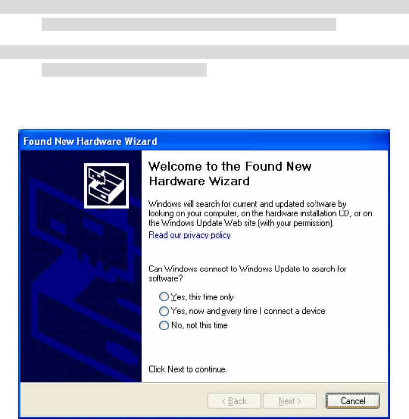
Before you proceed with the installation, please notice following descriptions.
Note1: The following installation was operated under Windows XP.
(Procedures are similar for Windows 98SE/Me/2000.)
Note2: If you have installed the USB WLAN driver & utility before, please
uninstall the old version first.
A. Ignore the following dialog. Please click “Cancel”.
6
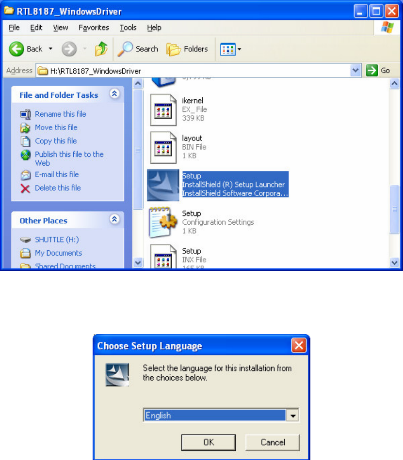
B. Insert the Installation CD to your CD-ROM Drive. Execute the “setup”
program.
C. Choose Setup Language
7
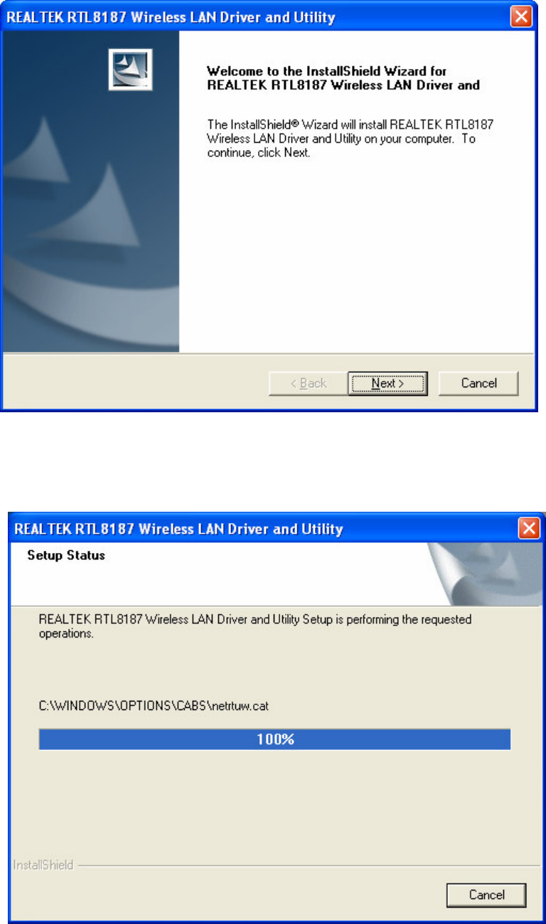
D. Click “Next” to process the installation
E. The system starts to install the software of the WLAN adapter.
8
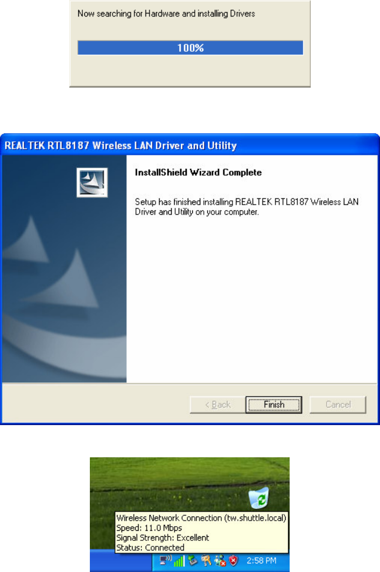
F. Please click “Finish” to complete the installation.
G. Now your PC has wireless network connection
9
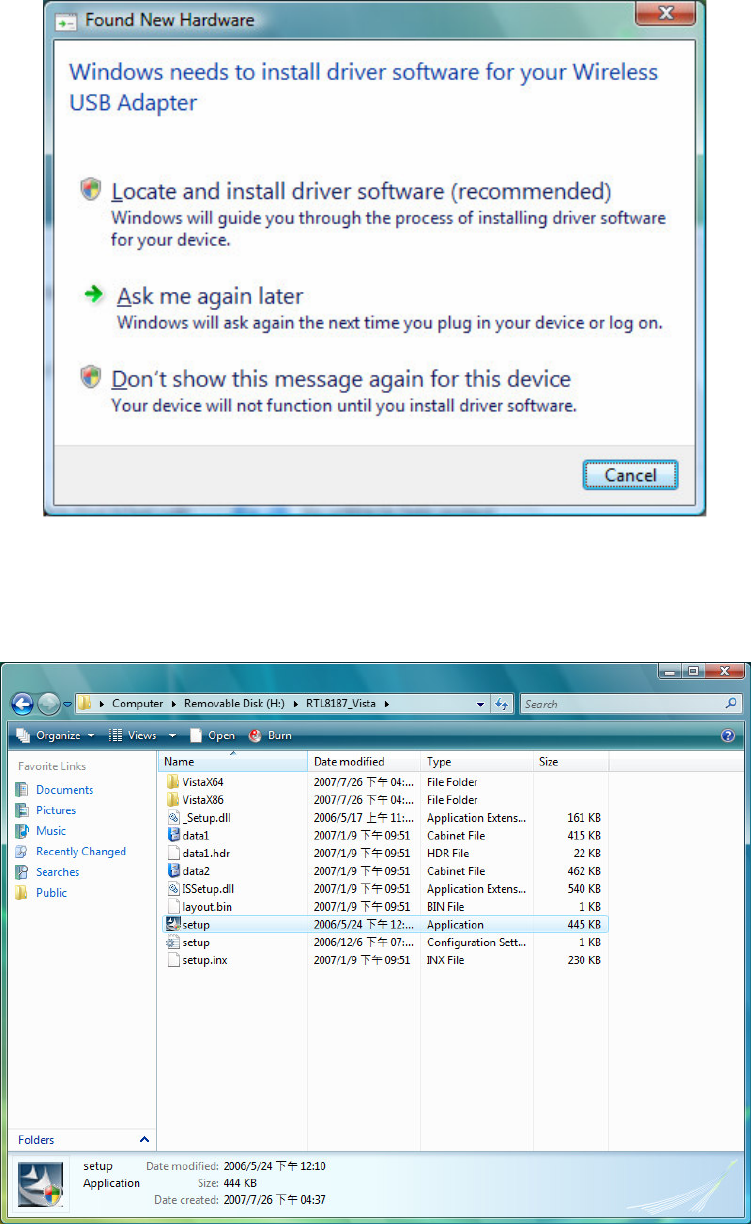
!
A. Ignore the following dialog. Please click “Cancel”.
B. Insert the Installation CD to your CD-ROM Drive. Execute the “setup”
program.
10
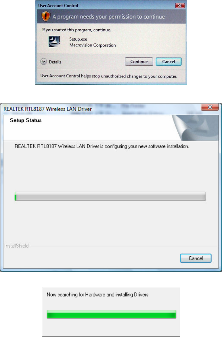
C. The system will automatically detect the card and display “Hardware
Installation” screen. Click “Continue” to continue.
11
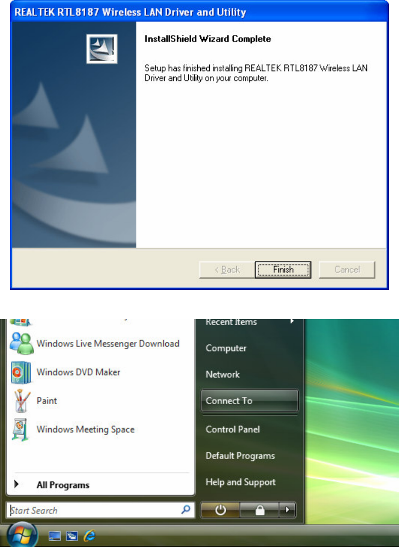
D. Please click “Finish” to complete the installation.
E. Please click the “Start” than select ”Connect To”
12
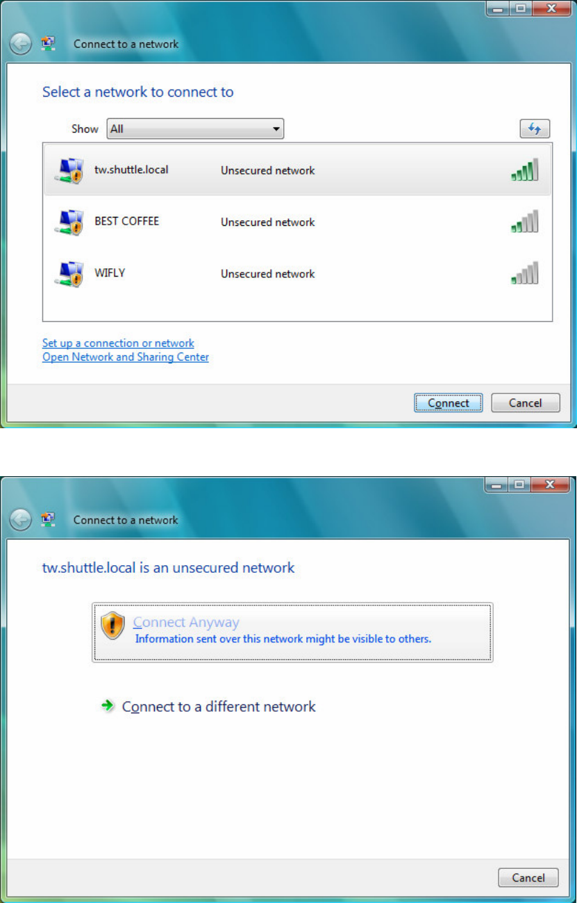
F. Please select your wireless network name and click “Connect”
G. Please click “Connect Anyway”
13
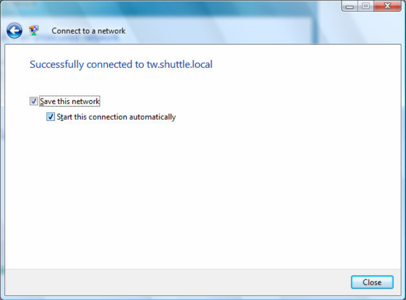
H. You can select “Save this network, Start this connection automatically”,
Windows will connect to wireless network on start up. Than click “Close”
to finish.
I. Now your PC has wireless network connection
14
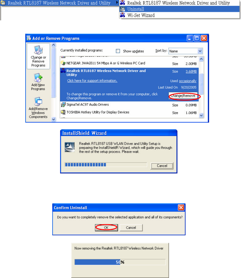
A. Uninstall the RTL8187 WLAN Driver from “Start” “All Programs”
“Realtek RTL8187 Wireless Network Driver and Utility” or “Control
Panel”“”“Change or Remove Programs”.
Please click “Un-istall” (or “Change/Remove”) to remove RTL8187 WLAN
driver.
B. Please click “OK” if you want to remove RTL8187 USB WLAN Driver.
`
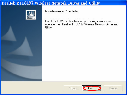
C. Please click “Finish” to complete the un-installation.
15
16
" #$%&'()
" &
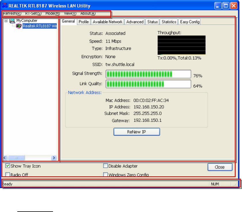
A. Main Menu
The main menu includes five submenus.
Refresh
As clicking the refresh menu, we can update and re-enumerate the
contents of adapter list area.
RT-Set
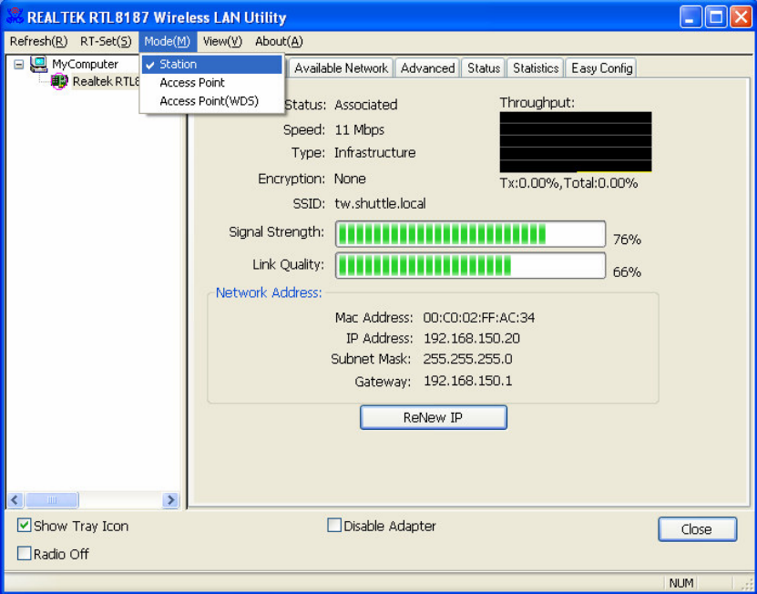
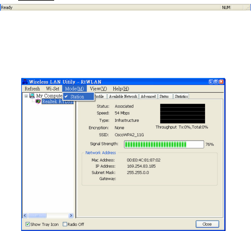
Mode
Wireless configuration was quickly switched to be either [Station] or
[Access Point] or [Access Point(WDS)].
A. Main Menu
B. Adapter List Area
C. Property Area
D. Global Control Bar
E. Status Bar
17
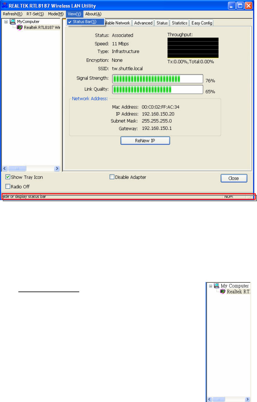
View
Enable/disable the present of status bar. Without check mark in front will
make the status bar hidden.
18
About
Click the item to show the about dialog. The application version and
license information are shown in the about dialog.
B. Adapter List Area
All connected adapters on this system for multiple adapter
installations are displayed in this area. It is easy for users to
change the selected adapter by one click. The contents of
properties area are dependant on wireless configuration that
the selected adapter was set up. If only single adapter was
installed on the system, only one adapter is always selected.
19
C. Properties Area
The contents of this area are dependent on current wireless configuration.
The current configuration is determined on previous explanation of submenu
“Mode”. The more detail contents are described in following wireless
configuration sections for both Station and AP mode.
D. Global Control Bar
Each control items on this bar affects the adapter or management GUI
directly.
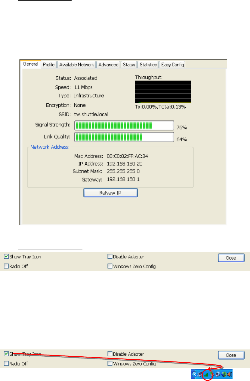
Show Tray Icon
Making this item to be checked and pressing “Close” button, the management
GUI will be minimized and stay on the tray icon located at the right down
corner of Windows. On the contrary, management GUI will shut down while
pressing “Close” button with unchecked condition.
Radio Off
Turn off the radio for saving power. While the radio being off, the links with
20
other wireless network nodes are disconnected. User should be care of it
while the wireless configuration is in AP mode. The radio off will cause the
sub network belong to the AP to disconnect with internet/intranet.
E. Status Bar
The hints or status of the management GUI are presented in the status bar.
" (
The following explanations focus on the properties area.
Infrastructure and Ad-Hoc
With both Infrastructure and Ad-Hoc types, the properties should looks like
the picture beside. Six property pages present different information of current
wireless network status.
Reading the following explanations before you reviewing these pages, it
could help you to well know the wireless environment around the system.
It is easy use to switch property pages just by left button clicking of mouse the
title of each page. The following six sections describe detail information of the
opposite page.
21
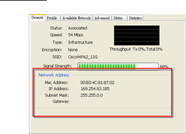
A. General page
This page represents the general information of this adapter.
1. Status
The connection status with access point this station has.
2. Speed
Current transition speed in Mbps.(Mega-Bits-Per-Second)
3. Type
Current wireless LAN configuration type
4. Encryption
Current encryption mode used
5. SSID
Name of wireless network
6. Signal Strength
The average quality of signal pf packets received from wireless network.
We recommend connecting access point with over 70% signal strength.
7. Throughput diagram
Current throughput, including transmission (Tx) and total traffic (Total).
8. Network Address group
Mac Address: six two-digital number of this adapter
IP Address: assigned network address by DHCP server or
self-definition in four three-digital number format
Subnet Mask: the only valid value is 2555.255.255.0
Gateway: It comes from connected access point. Your system can not
connect internet with this field empty.
1
2
3
4
5
6
7
8
22
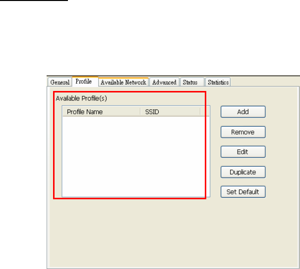
B. Profile page
This page provides profiles management like add, remove, edit and duplicate
just by pressing the button.
Available Profile(s)
The list box shows all the created profiles.
1. Add
Add a new profile for access point or IBSS (Ad-Hoc mode).
2. Remove
Remove the selected profile
3. Edit
Edit contents of selected profile
4. Duplicate
Make copy of selected profile.
5. Set Default
Set the selected profile as default selection.
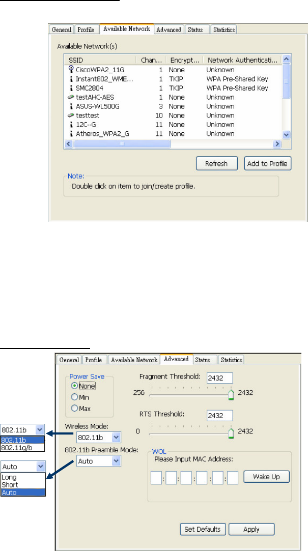
6. Available Network page
This page presents all BSS, including access points and IBSS, around this
system. And you could pick one of these network connections.
2
1
3
4
5
6
23
C. Available Network(s)
Present network connection around this system
1. Refresh
Rescan network connection around this system
2. Add to Profile
Create profile for selected network connection in profile list and add it in to
profile list.
D. Advanced page
1. Power Save
Γ None: without power save mode
Γ Min: wake up more frequently to receive packets
Γ Max: wake up less frequently to receive packets
2. Wireless Mode
Γ 802.11b
2
1
1
2
3
4
5
6
7
8
24
Γ 802.11g/b
3. 802.11b Preamble Mode
Γ Long: higher quality but with lower performance than preamble short
mode
Γ Short: Normal quality but with higher performance then preamble long
mode.
Γ Auto: use the preamble mode of current BSS.
4. Fragment Threshold
The threshold of fragment length. Higher threshold increase data
transition performance with good signal quality. However, in a poor signal
quality environment, data throughput might be worser on high fragment
threshold than low fragment threshold.
5. RTS Threshold
Threshold of Request To Send mechanism. The RTS frame will not send
out until the packet size over threshold.
6. WOL (Wake On LAN)
The wake-on-LAN is applied for remote control purpose. You could wake
up a system through network packets. For Realtek RTL8187 Wireless LAN
USB 2.0 Adapter, only the same adapter on another system could wake it
up.
Input MAC Address: the six two-digit numbers of Realtek RTL8187
Wireless LAN USB 2.0 Adapter on target system.
Wake Up: press this button to wake it up
7. Set Defaults
Restore the default value to be current setting
8. Apply
Apply the current setting to GUI
25
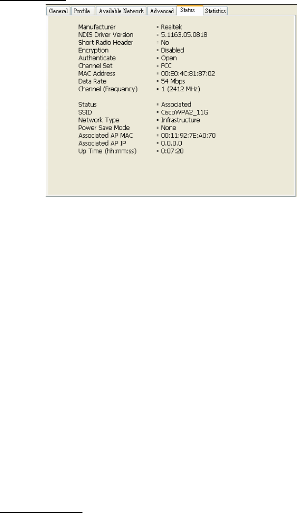
E. Status page
Manufacturer: It always is RealTek.
NDIS Driver Version:
Short Radio Header
Encryption: Current encryption mode.
Authenticate: authentication state
Channel Set: selected channel plan currently.
MAC Address: MAC address of this adapter.
Data Rate: wireless LAN transition speed
Channel(Frequency): current channel number
Status: wireless network status
SSID: name of connecting access point
Network Type: indicate current network configuration type
Power Save Mode: current setting power save mode
Associated AP MAC: MAC address of connecting access point
Associated AP IP: IP address of connecting access point
Up Time: total connection time
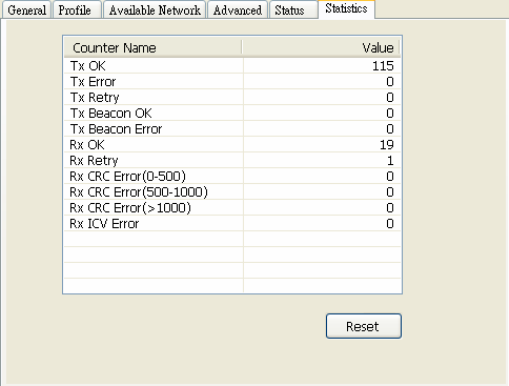
F. Statistics page
You could watch the Tx/Rx status of current wireless connection. This page
shows a statistic analysis of packet transition.
26

27
Federal Communication Commission Interference Statement
This equipment has been tested and found to comply with the limits for a Class B digital
device, pursuant to Part 15 of the FCC Rules. These limits are designed to provide
reasonable protection against harmful interference in a residential installation. This
equipment generates, uses and can radiate radio frequency energy and, if not installed
and used in accordance with the instructions, may cause harmful interference to radio
communications. However, there is no guarantee that interference will not occur in a
particular installation. If this equipment does cause harmful interference to radio or
television reception, which can be determined by turning the equipment off and on, the
user is encouraged to try to correct the interference by one of the following measures:
Reorient or relocate the receiving antenna
Increase the separation between the equipment and receiver.
Connect the equipment into an outlet on a circuit different from that to which the receiver is
connected.
Consult the dealer or an experienced radio/TV technician for help.
This device complies with Part 15 of the FCC Rules. Operation is subject to the following
two conditions:
(1) This device may not cause harmful interference, and
(2) this device must accept any interference received, including interference that may
cause undesired operation.
FCC Caution: Any changes or modifications not expressly approved by the party responsible
for compliance could void the user’ authority to operate this equipment.
IMPORTANT NOTE:
FCC Radiation Exposure Statement:
This equipment complies with FCC radiation exposure limits set forth for an uncontrolled
environment.
This transmitter must not be co-located or operating in conjunction with any other antenna or
transmitter.
IEEE 802.11b or 802.11g operation of this product in the U.S.A. is firmware-limited to channels
1 through 11.
This device is intended only for OEM integrators under the following conditions:
The transmitter module may not be co-located with any other transmitter or antenna.

28
As long as conduction above is met, further transmitter test will not be required. However, the
OEM integrator is still responsible for testing their end-product for any additional compliance
requirements required with this module installed (for example, digital device emissions, PC
peripheral requirements, etc.).
IMPORTANT NOTE: In the event that these conditions can not be met (for example certain
laptop configurations or co-location with another transmitter), then the FCC authorization is no
longer considered valid and the FCC ID can not be used on the final product. In these
circumstances, the OEM integrator will be responsible for re-evaluating the end product
(including the transmitter) and obtaining a separate FCC authorization.
End Product Labeling
The final end product must be labeled in a visible area with the following:
Contains TX FCC ID: S8C-PN20
Manual Information That Must be Included
The OEM integrator has to be aware not to provide information to the end user regarding how
to install or remove this RF module in the user’ manual of the end product which integrate this
module.
The users manual for OEM integrators must include the following information in a prominent
location
IMPORTANT NOTE: To comply with FCC RF exposure compliance requirements. The
antenna must not be co-located or operating in conjunction with any other antenna or
transmitter.
“To comply with FCC RF exposure compliance requirements, the antenna used for
this transmitter must be installed to provide a separation distance of at least 20 cm
from all persons and must not be co-located or operating in conjunction with any
other antenna or transmitter.