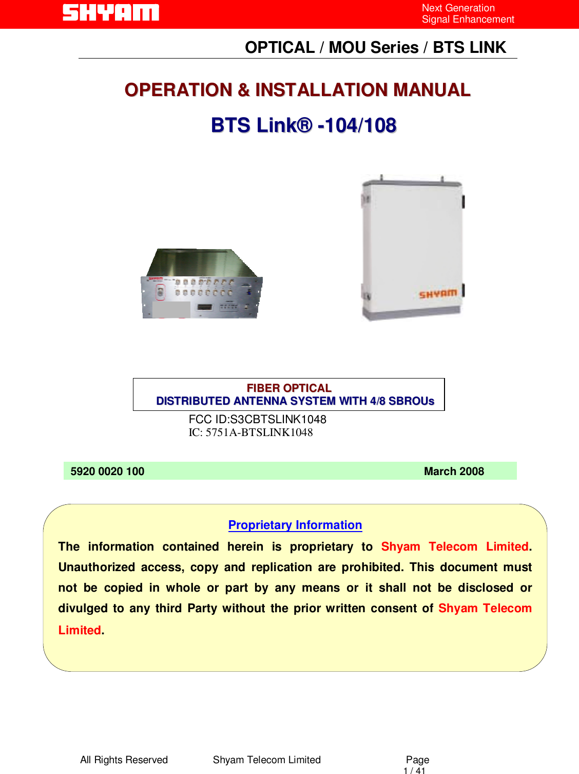
Shyam Telecom BTSLINK1048 BTS Link-104/108 Repeater User Manual
Shyam Telecom Inc. BTS Link-104/108 Repeater Users Manual
UserManual.wiki
>
Shyam Telecom
>
BTSLINK1048 User Manual
Users Manual
Navigation menu
Upload a User Manual
Namespaces
Wiki Guide
HTML
PDF
Info
Views
User Manual
Discussion / Help
Navigation
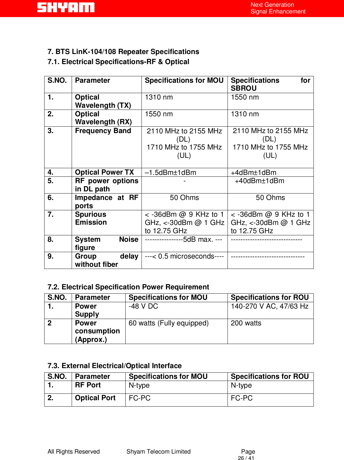
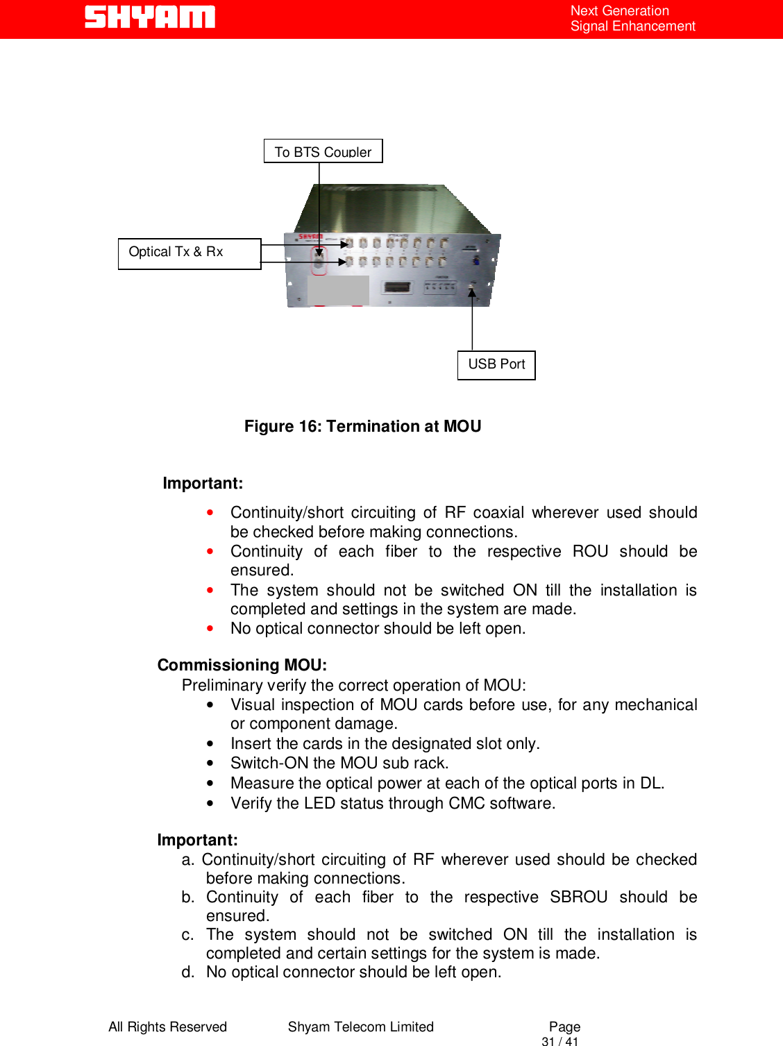
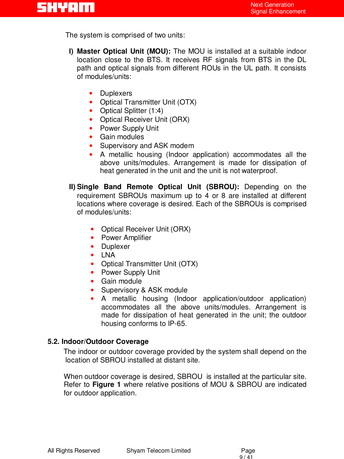
![All Rights Reserved Shyam Telecom Limited Page 7 / 41 Next Generation Signal Enhancement 4.4. References [1] ETS 300 086. Radio Equipment and Systems Land mobile service Technical characteristics and test conditions for radio equipment with an internal or external RF connector intended primarily for analogue speech. [2]ETS300609-4 Digital cellular telecommunications system (phase 2): Base Station Systems (BSS) equipment specification: Part 4: Repeaters. [3] ETS 300 342-3 Radio Equipment and Systems (RES), Electro-Magnetic Compatibility (EMC) for European Digital Cellular Telecommunications systems. Base Station Radio and ancillary equipment and Repeaters meeting phase 2 GSM requirements. 4.5. General Mobile Communications Systems are planned as cellular systems and each cell of the base station is required to provide RF coverage over a certain geographical area as per defined RF power levels. Due to the RF propagation properties, even using high radiated RF powers or complicated antenna systems, there are zones within the coverage area where the RF signal strength from base station remains inadequate for establishing the desired connectivity to mobile users. Repeaters traditionally are deployed in the Mobile Communication Network to fill in the “Dead Zones” caused by blocking of signals by geographic topologies such as mountains, valleys, dense foliage, high rise urban landscapes and other man-made structures. The distance from the base station also adversely affects the RF signal strength. The user views repeaters as a means to extend base station coverage so as to reduce the number of base stations and thereby accelerate network availability. Repeater systems are installed after meticulous planning between BTSs and the mobile users to provide RF coverage in the shadowed regions. Repeater systems are available for different applications and ultimate choice shall depend on some of the factors mentioned below: • Area to be provided with coverage. • Indoor/outdoor coverage. • Availability of BTSs in the vicinity.](https://usermanual.wiki/Shyam-Telecom/BTSLINK1048/User-Guide-1017229-Page-7.png)
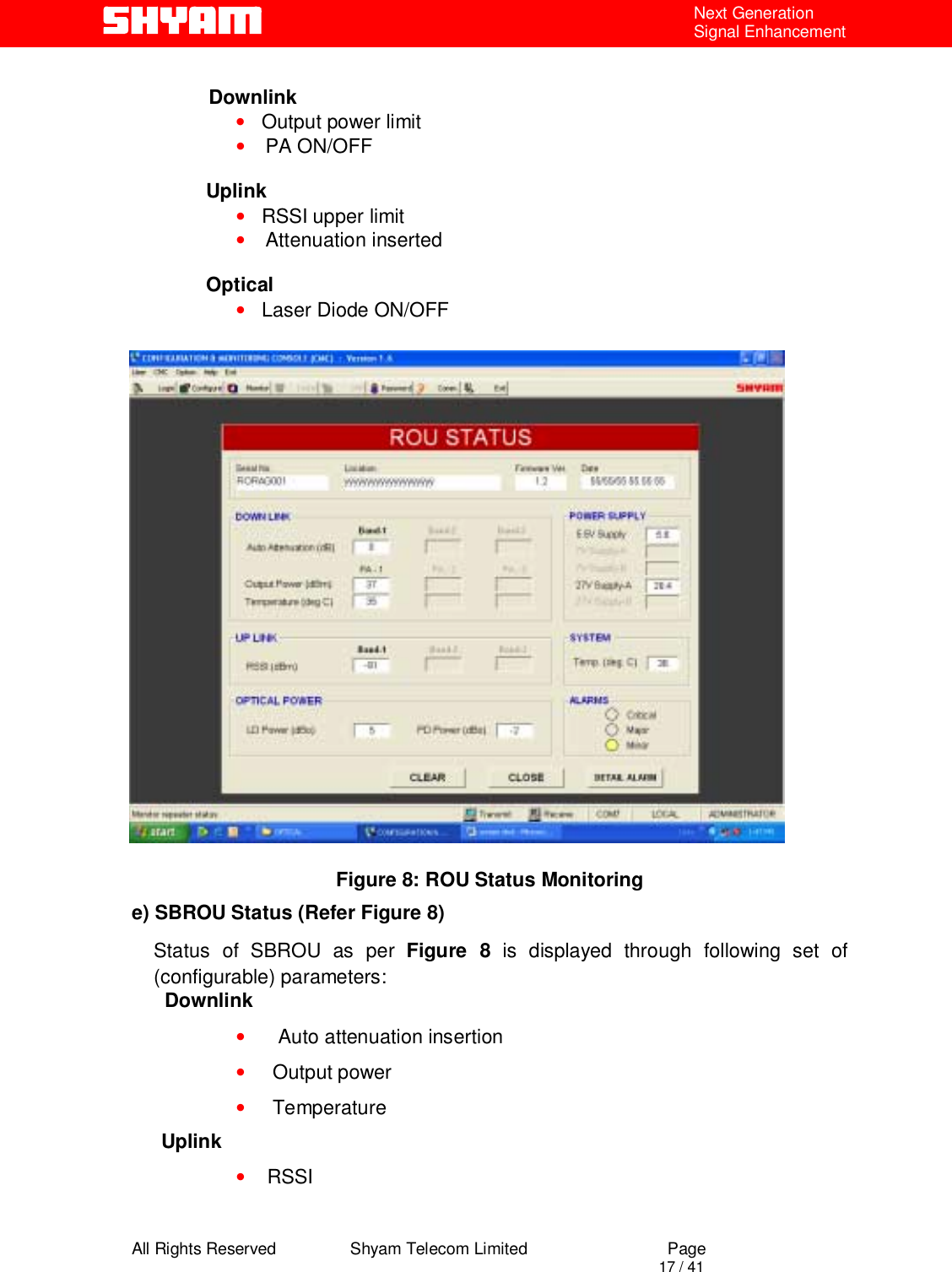
![All Rights Reserved Shyam Telecom Limited Page 13 / 41 Next Generation Signal Enhancement Downlink • RSSI • Attenuation inserted Uplink • Out put Power • Attenuation inserted Optical Power • OTX 1 & OTX 2 [Both units are equipped for 8 SBROUs] • ORX 1 to 8 [As per number of equipped SBROUs] Power Supply • 5.5 V Temperature • Displays the system temperature Alarms • Alarms as per categorization viz. Critical, Major and Minor. Clicking at “detail alarms” can further check the associated detail. In addition to above it also displays: • MOU Serial No. • Location of MOU • Firmware incorporated in the unit • Date](https://usermanual.wiki/Shyam-Telecom/BTSLINK1048/User-Guide-1017229-Page-13.png)
![All Rights Reserved Shyam Telecom Limited Page 15 / 41 Next Generation Signal Enhancement Figure 5: MOU Status Monitoring C) Alarms-MOU (Refer Figure 6) Alarm Observed Detail DL RSSI low It indicates that the RSSI has gone below the set limit. DL RSSI High It indicates that the RSSI has exceeded the higher limit set. UL Power High When the high power than the set limit is detected, it is indicated. LD off [OTX-1 & OTX-2] It indicates the OFF status of LD corresponding to OTX-1/OTX-2. LD Power Low [OTX-1 & OTX-2] It indicates the detection of low optical power in LD corresponding to OTX-1/OTX-2. LD Power High [OTX-1 & OTX-2] It indicates the detection of high optical power in LD corresponding to OTX-1/OTX-2. Photo Diode Power Low [ORX-1 to ORX-8] It indicates the detection of low optical power in PD corresponding to ORX-1 to ORX-8. Photo Diode Power High [ORX-1 to ORX-8] It indicates the detection of high optical power in PD corresponding to ORX-1 to ORX-8. Power Supply Failure of derived DC voltage is indicated. System Temperature High When the system temperature exceeds the set limit, alarm will be generated.](https://usermanual.wiki/Shyam-Telecom/BTSLINK1048/User-Guide-1017229-Page-15.png)
![All Rights Reserved Shyam Telecom Limited Page 16 / 41 Next Generation Signal Enhancement Figure 6: MOU Alarm Monitoring Figure 7: SBROU Settings d) Settings in SBROU [Figure 7] After login, following setting is carried out:](https://usermanual.wiki/Shyam-Telecom/BTSLINK1048/User-Guide-1017229-Page-16.png)
![All Rights Reserved Shyam Telecom Limited Page 18 / 41 Next Generation Signal Enhancement Optical Power • LD power • PD power In addition to above parameters, following parameters are also displayed: • Derived DC voltages • System temperature • Alarms – Category [Detail can be seen on Alarm window] Figure 9: SBROU Alarms Monitoring f) Alarms-SBOU (Refer Figure 9) Alarm Observed Detail PA OFF DL (Manual) When the user sets PA ON / OFF command as OFF, alarm will be generated. PA OFF DL (Auto) When the system sets the PA OFF, alarm will be generated. PA Power High DL When PA power exceeds the limit set by the user, alarm will be generated. PA Power Low DL When PA power goes lower than the limit set by the user, alarm will be generated. PA Temperature High It indicates that the temperature has exceeded the limits. LNA UL LNA failure is indicated. Laser Diode OFF Failure of Laser Tx power is indicated.](https://usermanual.wiki/Shyam-Telecom/BTSLINK1048/User-Guide-1017229-Page-18.png)
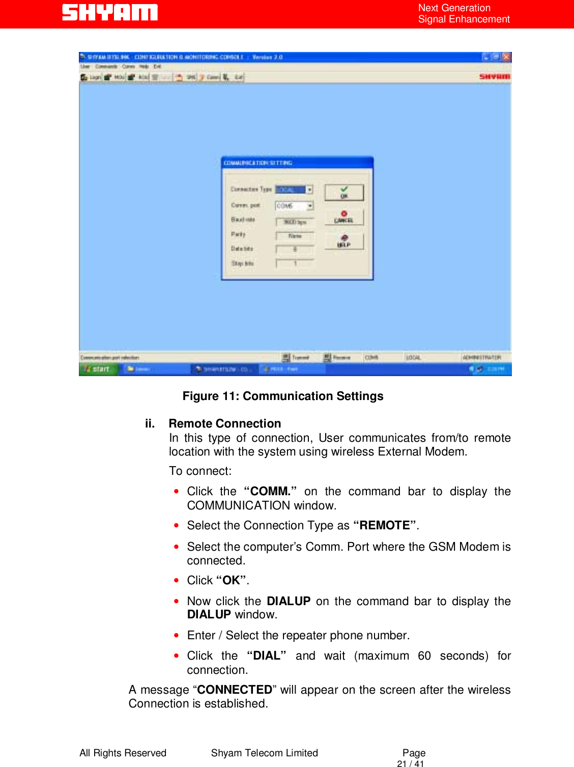
![All Rights Reserved Shyam Telecom Limited Page 20 / 41 Next Generation Signal Enhancement Figure 10: Selection of SBROU for Status & Alarm Monitoring III) Communication Setting [Figure 11] It is possible to establish communication with MOU & ROU through the software incorporated in the system. i. Local Connection In this type of connection, user computer COM Port and system’s USB port are connected directly using cable. Proceed as under: • Click the “COMM.” on the command bar to display the COMMUNICATION window. • Select the Connection Type as “LOCAL” • Select the computer’s Comm. Port where the repeater is connected. • Click “OK”.](https://usermanual.wiki/Shyam-Telecom/BTSLINK1048/User-Guide-1017229-Page-20.png)
![All Rights Reserved Shyam Telecom Limited Page 22 / 41 Next Generation Signal Enhancement Click the “DISCONNECT” on the DIALUP window to disconnect remote communication with the system. IV) SECURITY [Figure 12] Password Setting Select Password setting from Security menu to change the existing Password. If logged in user is SUPERVISOR, the password for SUPERVISOR only, can be changed. The ADMINISTRATOR can perform all the functions including change of the password for ADMINISTRATOR & SUPERVISOR. Figure 12: Password Setting CAUTION When the communication between repeater & PC/Laptop is in progress through USB: • Do not remove cable from the USB port. • Do not switch off the repeater. In case the communication is not required any more, click at EXIT before removing cable from USB port to avoid hanging of the PC/Laptop. In case the PC/Laptop goes in to hanging mode, it has to be restarted after closing/switching OFF & ON the repeater.](https://usermanual.wiki/Shyam-Telecom/BTSLINK1048/User-Guide-1017229-Page-22.png)