Shyam Telecom BTSLINK1048 BTS Link-104/108 Repeater User Manual
Shyam Telecom Inc. BTS Link-104/108 Repeater Users Manual
Users Manual
All Rights Reserved Shyam Telecom Limited Page
1 / 41
Next Generation
Signal Enhancement
OPTICAL / MOU Series / BTS LINK
O
OP
PE
ER
RA
AT
TI
IO
ON
N
&
&
I
IN
NS
ST
TA
AL
LL
LA
AT
TI
IO
ON
N
M
MA
AN
NU
UA
AL
L
B
BT
TS
S
L
Li
in
nk
k®
®
-
-1
10
04
4/
/1
10
08
8
FCC ID:S3CBTSLINK1048
IC: 5751A-BTSLINK1048
5920 0020 100
March
200
8
Proprietary Information
The information contained herein is proprietary to Shyam Telecom Limited.
Unauthorized access, copy and replication are prohibited. This document must
not be copied in whole or part by any means or it shall not be disclosed or
divulged to any third Party without the prior written consent of Shyam Telecom
Limited.
F
F
I
I
B
B
E
E
R
R
O
O
P
P
T
T
I
I
C
C
A
A
L
L
D
D
I
I
S
S
T
T
R
R
I
I
B
B
U
U
T
T
E
E
D
D
A
A
N
N
T
T
E
E
N
N
N
N
A
A
S
S
Y
Y
S
S
T
T
E
E
M
M
W
W
I
I
T
T
H
H
4
4
/
/
8
8
S
S
B
B
R
R
O
O
U
U
s
s

All Rights Reserved Shyam Telecom Limited Page
2 / 41
Next Generation
Signal Enhancement
INDEX
1. DOCUMENT HISTORY .......................................................................................... 3
2. DISCLAIMER........................................................................................................... 4
3. SAFETY INSTRUCTIONS AND WARNINGS....................................................... 4
3.1. PERSONNEL SAFETY .....................................................................................4
3.2. EQUIPMENT SAFETY......................................................................................4
3.3. ELECTROSTATIC SENSITIVITY.........................................................................5
4. INTRODUCTION..................................................................................................... 6
4.1. PURPOSE .....................................................................................................6
4.2. SCOPE .........................................................................................................6
4.3. DEFINITIONS.................................................................................................6
4.4. REFERENCES................................................................................................7
4.5. GENERAL .....................................................................................................7
5. FUNCTIONAL DESCRIPTION OF BTS LINK-104/108 REPEATER ................. 8
5.1. GENERAL DESCRIPTION.................................................................................8
5.2. INDOOR/OUTDOOR COVERAGE.......................................................................9
6. TO GET STARTED-BASIC SOFTWARE CONTROL OF THE SYSTEM ....... 11
6.1. GENERAL ...................................................................................................11
6.2. TERMINAL SET-UP.......................................................................................11
6.3. BLOCK DESCRIPTION...................................................................................23
7. BTS LINK-104/108 REPEATER SPECIFICATIONS .......................................... 26
7.1. ELECTRICAL SPECIFICATIONS-RF & OPTICAL ................................................26
7.2. ELECTRICAL SPECIFICATION POWER REQUIREMENT ......................................26
7.3. EXTERNAL ELECTRICAL/OPTICAL INTERFACE.................................................26
7.4. MECHANICAL SPECIFICATION .......................................................................27
7.5. ENVIRONMENTAL SPECIFICATION..................................................................27
7.6. CONTENTS OF DELIVERY .............................................................................27
7.7. SAFETY PRECAUTIONS-HANDLING OPTICAL EQUIPMENT ................................27
8. INSTALLATION .................................................................................................... 29
8.1. PREPARATION SHEET-PRE INSTALLATION .....................................................29
8.2. MOU INSTALLATION....................................................................................30
8.3. OPTICAL FIBER LAYING................................................................................32
8.4. INSTALLATION-SBROU ...............................................................................33
8.5. DOS & DON’T DOS ......................................................................................34
8.6. CHECKLIST-POST INSTALLATION...................................................................35
9. SYSTEM MAINTENANCE.................................................................................... 37
9.1. GENERAL ...................................................................................................37
9.2. PREVENTATIVE MAINTENANCE .....................................................................37

All Rights Reserved Shyam Telecom Limited Page
3 / 41
Next Generation
Signal Enhancement
1. Document History
Document
Number Document
Name Date Compiled
by Approved
by Revision
5920 0020 100 BTS Link-
104/108
Repeater
March
2008 Inderjit Rajeev Sarup
Revision Revised Section Date
Intentionally Left Blank

All Rights Reserved Shyam Telecom Limited Page
4 / 41
Next Generation
Signal Enhancement
2. Disclaimer
Every attempt has been made to make this material complete, accurate,
and up-to-date. Users are cautioned, however, that Shyam Telecom
Limited reserves the right to make changes without notice and shall not be
responsible for any damages including consequential, caused by reliance of
the contents presented, including, but not limited to, typographical,
arithmetical, or listing errors.
Product name(s) referenced in this document may be trademarks or
registered trademarks of their respective companies, and are hereby
acknowledged.
In areas with unstable power grids (mains) all repeaters must be installed
with a voltage regulator ensuring a constant voltage level at the repeater
power input. A maximum voltage deviation should remain within the input
range to the repeaters for warranty purposes.
All antennas must be installed with lighting protection. Damage to internal
modules, as a result of lightning is not covered by the warranty.
All specifications are subject to change without prior notice
3. Safety Instructions and Warnings
3.1. Personnel Safety
Before installing or replacing any equipment, the entire manual should be
read and understood. The user needs to supply the appropriate AC power
to the Repeater. Incorrect AC power settings can damage the repeater and
may cause injury to the user.
Throughout this manual, there are "Caution" warnings, "Caution" calls
attention to a procedure or practice, which, if ignored, may result in injury
or damage to the system or system component or even the user. Do not
perform any procedure preceded by a "Caution" until the described
conditions are fully understood and met.
3.2. Equipment Safety
When installing, replacing or using this product, observe all safety
precautions during handling and operation. Failure to comply with the
following general safety precautions and with specific precautions described
elsewhere in this manual violates the safety standards of the design,
manufacture, and intended use of this product. Shyam Telecom Limited
assumes no liability for the customer's failure to comply with these
precautions. This entire manual should be read and understood before
operating or maintaining the repeater system.

All Rights Reserved Shyam Telecom Limited Page
5 / 41
Next Generation
Signal Enhancement
CAUTION
It calls attention to a procedure or practice, which, if not followed, may
result in personal injury, damage to the system or damage to individual
components. Do not perform any procedure preceded by a
CAUTION until described conditions are fully understood and met.
3.3. Electrostatic Sensitivity
CAUTION
ESD = ELECTROSTATIC DISCHARGE SENSITIVE DEVICE
Observe electrostatic precautionary procedures.
Semiconductor transmitters and receivers provide highly reliable
performance when operated in conformity with the intentions of their design.
However, a semiconductor may be damaged by an electrostatic charge
inadvertently imposed by careless handling.
Static electricity can be conducted to the semiconductor chip from the
centre pin of the RF input connector, and through the AC connector pins.
When unpacking and otherwise handling the Repeater, follow ESD
precautionary procedures including the use of grounded wrist straps,
grounded workbench surfaces, and grounded floor mats.

All Rights Reserved Shyam Telecom Limited Page
6 / 41
Next Generation
Signal Enhancement
4. Introduction
4.1. Purpose
The purpose of this document is to describe the electrical and mechanical
specifications, operation and maintenance of the BTS Link-104/108
Repeater.
4.2. Scope
This document is the product description of the Shyam BTS Link-104/108
Repeater.
4.3. Definitions
AGC Automatic Gain Control
ALC Automatic Level Control
APC Automatic Power Control
BTS Base Transceiver Station
CDMA Coded Division Multiple Access
CMC Configuration & Monitoring Console software
DCS Digital Communication System
DL Downlink signal (from base station via repeater to
mobile station)
EGSM Extended Global System for Mobile Communication
ETSI European Telecommunications Standard Institute
FDF Fiber Distribution Frame
GSM Global System for Mobile communication
LED Light Emitting Diode
LNA Low Noise Amplifier
LO Local Oscillator
MOU Master Optical Unit
MS Mobile Station
PCN Personal Communication Network
PCS Personal Communication System
PSU Power Supply Unit
RF Radio Frequency
RMS Remote Management System
ROU Remote Optical Unit
RSSI Received Signal Strength Indication
UL (Uplink) Uplink signal direction (from mobile station via
repeater to base station)
UMTS Universal Mobile Telecommunication System

All Rights Reserved Shyam Telecom Limited Page
7 / 41
Next Generation
Signal Enhancement
4.4. References
[1] ETS 300 086.
Radio Equipment and Systems Land mobile service Technical
characteristics and test conditions for radio equipment with an internal or
external RF connector intended primarily for analogue speech.
[2]ETS300609-4
Digital cellular telecommunications system (phase 2): Base Station
Systems (BSS) equipment specification: Part 4: Repeaters.
[3] ETS 300 342-3
Radio Equipment and Systems (RES), Electro-Magnetic Compatibility
(EMC) for European Digital Cellular Telecommunications systems. Base
Station Radio and ancillary equipment and Repeaters meeting phase 2
GSM requirements.
4.5. General
Mobile Communications Systems are planned as cellular systems and each
cell of the base station is required to provide RF coverage over a certain
geographical area as per defined RF power levels. Due to the RF
propagation properties, even using high radiated RF powers or complicated
antenna systems, there are zones within the coverage area where the RF
signal strength from base station remains inadequate for establishing the
desired connectivity to mobile users.
Repeaters traditionally are deployed in the Mobile Communication Network
to fill in the “Dead Zones” caused by blocking of signals by geographic
topologies such as mountains, valleys, dense foliage, high rise urban
landscapes and other man-made structures. The distance from the base
station also adversely affects the RF signal strength. The user views
repeaters as a means to extend base station coverage so as to reduce the
number of base stations and thereby accelerate network availability.
Repeater systems are installed after meticulous planning between BTSs
and the mobile users to provide RF coverage in the shadowed regions.
Repeater systems are available for different applications and ultimate
choice shall depend on some of the factors mentioned below:
• Area to be provided with coverage.
• Indoor/outdoor coverage.
• Availability of BTSs in the vicinity.

All Rights Reserved Shyam Telecom Limited Page
8 / 41
Next Generation
Signal Enhancement
5. Functional Description of BTS Link-104/108 Repeater
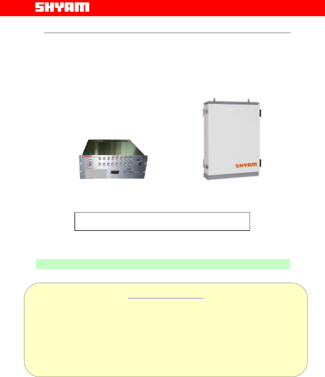
5.1. General Description
The BTS Link-104/108 Repeater System is designed to provide
indoor/outdoor coverage (depending on the location of the remote optical
unit installed) and is equipped to handle signals in AWS band. It provides
highly selective amplification in the pre-set band. The detail of operating
AWS service frequency band is given below:
Frequency Band:
Down Link: 2110 MHz to 2155 MHz
Up Link : 1710 MHz to 1755 MHz
The Customer is requested to refer to the sticker on the repeater unit
giving the details of frequency band set.
• The BTS Link-104/108 repeater system is a single band
Distributed Antenna System (DAS) for point to point & point to multi-
point coverage.
• It is comprised of a Master Optical Unit (MOU) and Single Band
Remote Optical Units (SBROUs), maximum 4 or 8, installed at
different sites. Two versions are available; BTS Link-104 version
supports up to 4 SBROUs and BTS Link-108 supports up to 8
SBROUs. MOU & each of the SBROUs are connected through a
pair of optical fibers.
• For providing coverage in a large area, SBROUs with RF power of
+40dBm can bs installed.
• Master Optical Unit (MOU) is installed at indoor location close to
BTS from where the signals are to be received and OFC
terminations destined for SBROUs at different sites are available.
• The repeater is deployed in the network where RF coverage is
required for large clusters of mobile users at different sites.
• The repeater can be equipped with a RMS (Optional) for speedy
maintenance & monitoring.
• The antenna isolation problem is of little consequence since the
signals between MOU and SBROUs are propagated as optical
signals, which are insensitive to any electrical
interference/disturbances.

All Rights Reserved Shyam Telecom Limited Page
9 / 41
Next Generation
Signal Enhancement
The system is comprised of two units:
I) Master Optical Unit (MOU): The MOU is installed at a suitable indoor
location close to the BTS. It receives RF signals from BTS in the DL
path and optical signals from different ROUs in the UL path. It consists
of modules/units:
• Duplexers
• Optical Transmitter Unit (OTX)
• Optical Splitter (1:4)
• Optical Receiver Unit (ORX)
• Power Supply Unit
• Gain modules
• Supervisory and ASK modem
• A metallic housing (Indoor application) accommodates all the
above units/modules. Arrangement is made for dissipation of
heat generated in the unit and the unit is not waterproof.
II) Single Band Remote Optical Unit (SBROU): Depending on the
requirement SBROUs maximum up to 4 or 8 are installed at different
locations where coverage is desired. Each of the SBROUs is comprised
of modules/units:
• Optical Receiver Unit (ORX)
• Power Amplifier
• Duplexer
• LNA
• Optical Transmitter Unit (OTX)
• Power Supply Unit
• Gain module
• Supervisory & ASK module
• A metallic housing (Indoor application/outdoor application)
accommodates all the above units/modules. Arrangement is
made for dissipation of heat generated in the unit; the outdoor
housing conforms to IP-65.
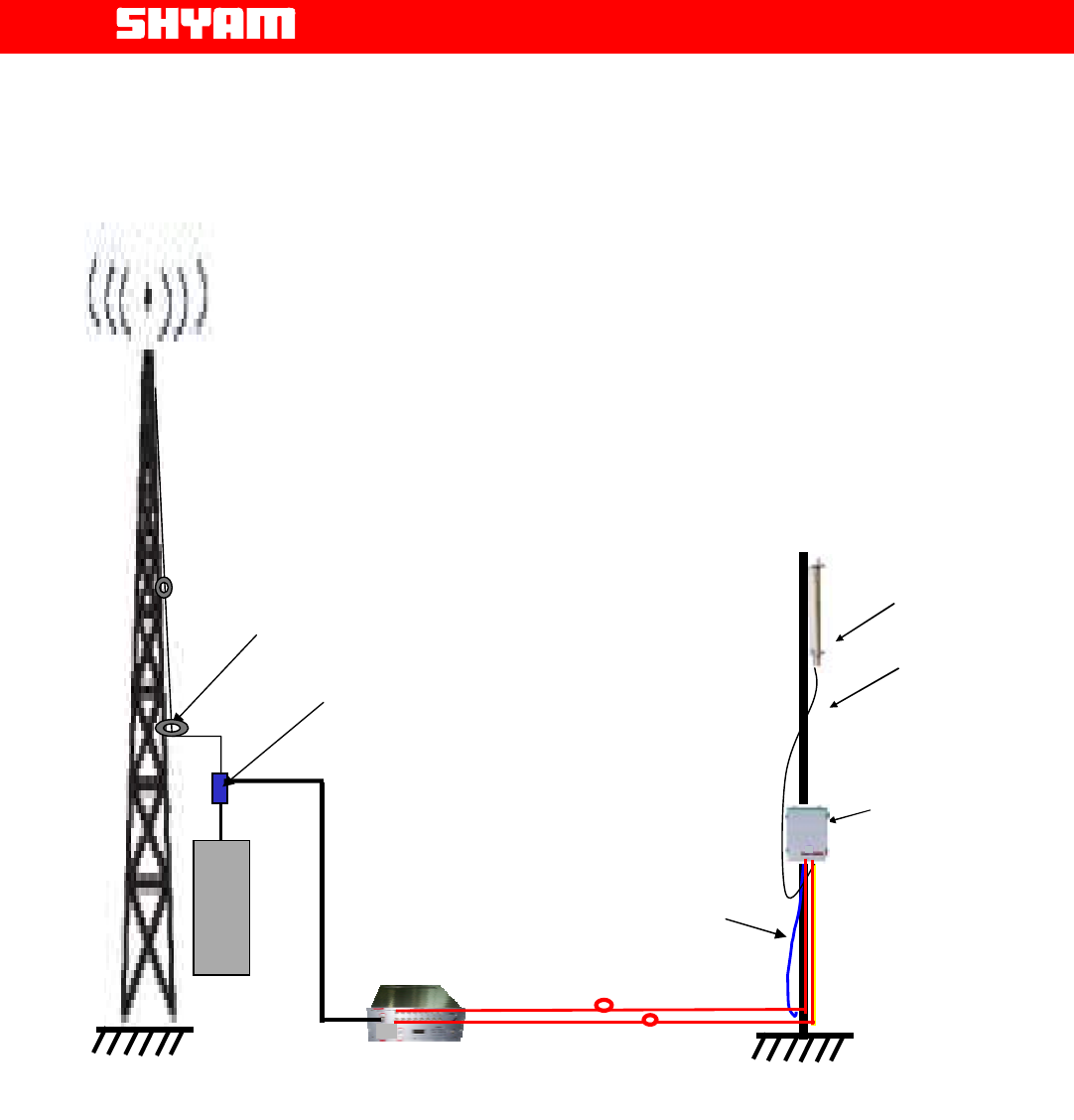
5.2. Indoor/Outdoor Coverage
The indoor or outdoor coverage provided by the system shall depend on the
location of SBROU installed at distant site.
When outdoor coverage is desired, SBROU is installed at the particular site.
Refer to Figure 1 where relative positions of MOU & SBROU are indicated
for outdoor application.
All Rights Reserved Shyam Telecom Limited Page
10 / 41
Next Generation
Signal Enhancement
Figure 1: Typical Outdoor Application of BTS-Link 104/108
Optical Fiber
B
T
S
Directional Coupler
MOU Installed inside BTS enclosure
RF Cable Clamp
SBROU
Server
Antenna
Power supply
cable
RF cable from
antenna
All Rights Reserved Shyam Telecom Limited Page
11 / 41
Next Generation
Signal Enhancement
6. To Get started-Basic Software Control of the System
6.1. General
The system (MOU & SBROU) is equipped with a supervisory module that
allows the monitoring and control of various parameters such as RF power,
attenuation, temperature, status of door and alarm conditions etc.
The communication interface between the local terminal and the control
module can be set up using the Configuration & Monitoring Console
software (CMC), which is an easy to use GUI for simple control and
monitoring. It enables monitoring of parameters & subsequent adjustment if
required.
This function can be performed either using a terminal (PC/laptop) locally,
or through remote login using the wireless modem (Optional) located in the
repeater. USB port is provisioned in the equipment for connecting
PC/laptop.
6.2. Terminal Set-up
The system is delivered with software loaded in order to perform
configuration as per requirement. It also enables monitoring the status.
Configuration of parameters can be carried out locally at MOU & ROU with
a laptop / PC connected to the system by means of local USB serial
interface or remotely via wireless modem (Optional) mounted inside the
MOU. The laptop/PC should be loaded with the CMC software available on
the supplied CD along with the USB driver.
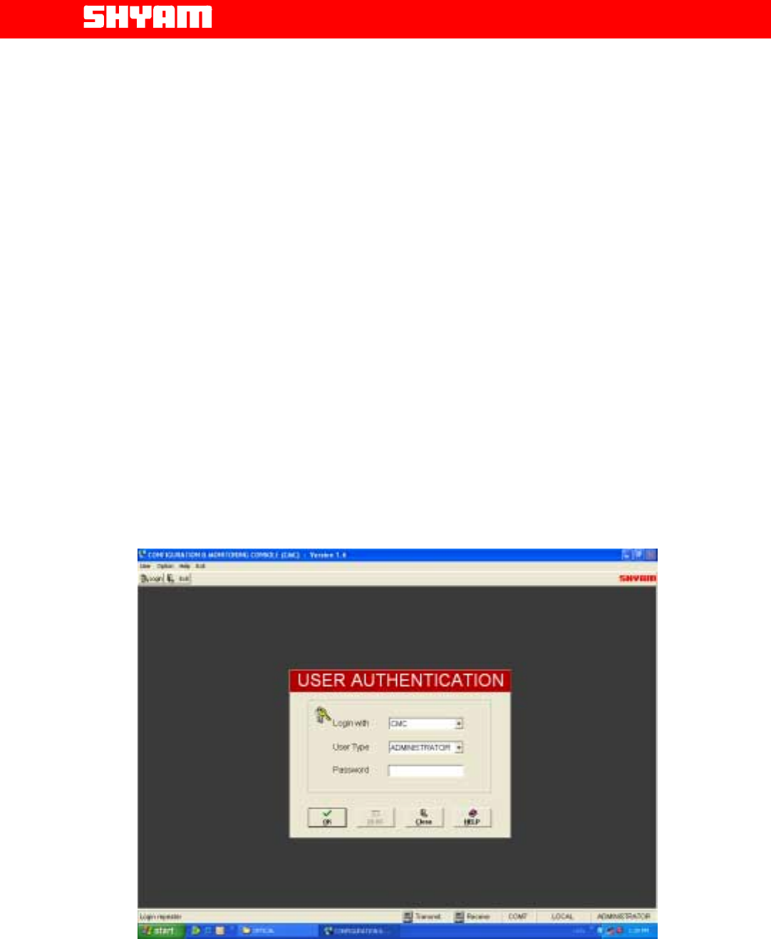
Figure 2: Login Repeater

All Rights Reserved Shyam Telecom Limited Page
12 / 41
Next Generation
Signal Enhancement
Functions as described below are carried out through CMC software:
I) Login Repeater (Figure 2)
After running the system Configuration & Monitoring Console (CMC),
user needs to login. Similar sequence is to be followed at MOU &
SBROU. To login:
• Click the “Login” on the command bar.
• Select the user type.
• Enter the password.
• Finally click the “OK”.
After successful login, a message “Logged in successfully” will be
flashed on the screen. Now user can start the operation through CMC.
There are two type of user viz. ADMINISTRATOR and SUPERVISOR. If
user logged in as an ADMINISTRATOR, all the operation through the
CMC can be carried out. Default password is “SHYAM”.
SUPERVISOR is allowed to perform monitoring of the status & alarms
but no change in configuration is permitted. However, the SUPERVISOR
can change password if so desired.
II) Configuration & Monitoring
Configuring system means setting the system parameters for operation
as per the requirement at site. Configuration & monitoring is carried out
at MOU and ROU separately.
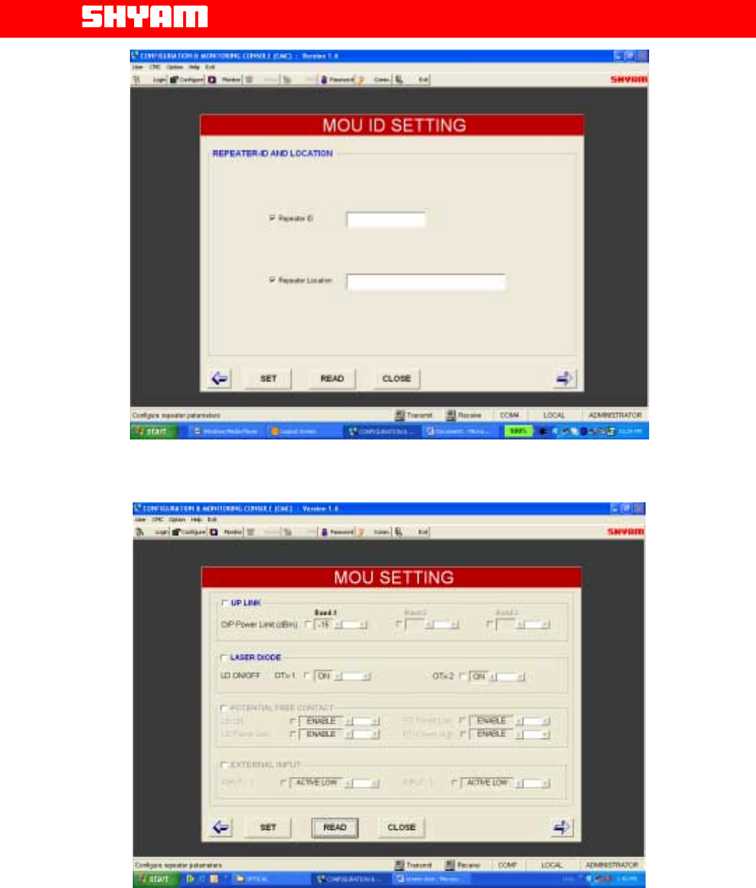
a) Settings in MOU
To begin with MOU ID settings as per Figure 3 are carried out,
information specified is:
• Repeater ID
• Repeater Location
Configurable parameters as per Figure 4 are:
• Out put power limit UL
• Laser Diode ON/OFF
• OTX1 ON/OFF and OTX2 ON/OFF
After specifying these parameters, SET is pressed
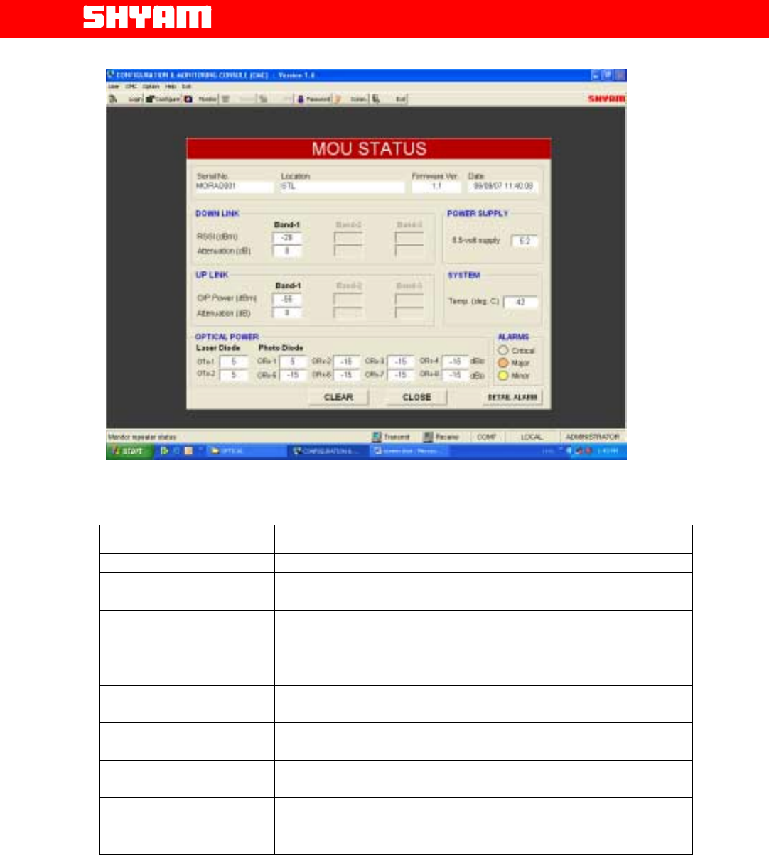
b) MOU Status
Status of MOU as per Figure 5 is displayed through following set
(configurable) parameters:

All Rights Reserved Shyam Telecom Limited Page
13 / 41
Next Generation
Signal Enhancement
Downlink
• RSSI
• Attenuation inserted
Uplink
• Out put Power
• Attenuation inserted
Optical Power
• OTX 1 & OTX 2 [Both units are equipped for 8 SBROUs]
• ORX 1 to 8 [As per number of equipped SBROUs]
Power Supply
• 5.5 V
Temperature
• Displays the system temperature
Alarms
• Alarms as per categorization viz. Critical, Major and Minor.
Clicking at “detail alarms” can further check the associated
detail.
In addition to above it also displays:
• MOU Serial No.
• Location of MOU
• Firmware incorporated in the unit
• Date
All Rights Reserved Shyam Telecom Limited Page
14 / 41
Next Generation
Signal Enhancement
Figure 3: MOU ID Settings
Figure 4: MOU Settings
All Rights Reserved Shyam Telecom Limited Page
15 / 41
Next Generation
Signal Enhancement
Figure 5: MOU Status Monitoring
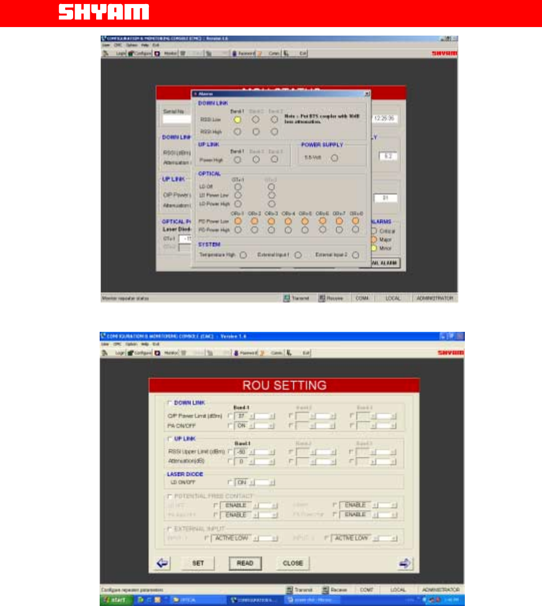
C) Alarms-MOU (Refer Figure 6)
Alarm Observed Detail
DL RSSI low It indicates that the RSSI has gone below the set limit.
DL RSSI High It indicates that the RSSI has exceeded the higher limit set.
UL Power High When the high power than the set limit is detected, it is indicated.
LD off
[OTX-1 & OTX-2] It indicates the OFF status of LD corresponding to OTX-1/OTX-2.
LD Power Low
[OTX-1 & OTX-2] It indicates the detection of low optical power in LD corresponding to
OTX-1/OTX-2.
LD Power High
[OTX-1 & OTX-2] It indicates the detection of high optical power in LD corresponding to
OTX-1/OTX-2.
Photo Diode Power Low
[ORX-1 to ORX-8] It indicates the detection of low optical power in PD corresponding to
ORX-1 to ORX-8.
Photo Diode Power High
[ORX-1 to ORX-8] It indicates the detection of high optical power in PD corresponding
to ORX-1 to ORX-8.
Power Supply Failure of derived DC voltage is indicated.
System Temperature
High When the system temperature exceeds the set limit, alarm will be
generated.
All Rights Reserved Shyam Telecom Limited Page
16 / 41
Next Generation
Signal Enhancement
Figure 6: MOU Alarm Monitoring
Figure 7: SBROU Settings
d) Settings in SBROU [Figure 7]
After login, following setting is carried out:
All Rights Reserved Shyam Telecom Limited Page
17 / 41
Next Generation
Signal Enhancement
Downlink
• Output power limit
• PA ON/OFF
Uplink
• RSSI upper limit
• Attenuation inserted
Optical
• Laser Diode ON/OFF
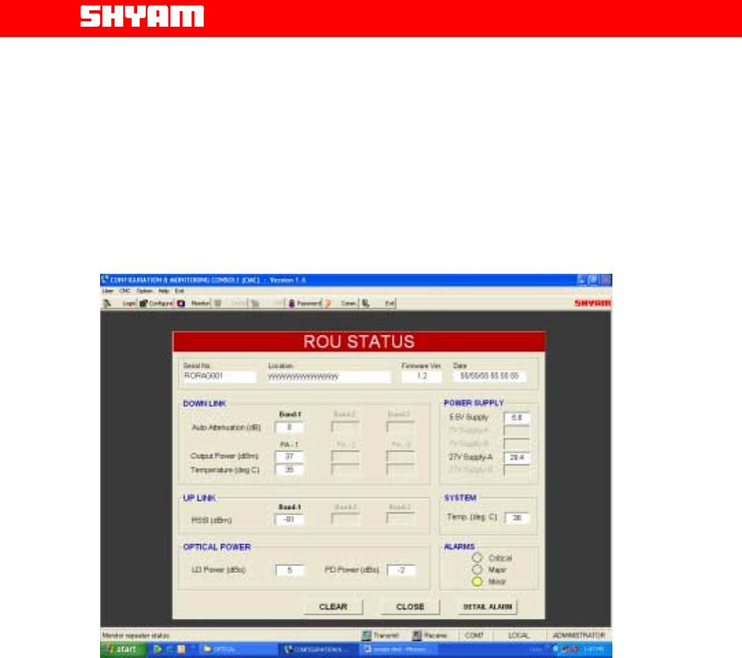
Figure 8: ROU Status Monitoring
e) SBROU Status (Refer Figure 8)
Status of SBROU as per Figure 8 is displayed through following set of
(configurable) parameters:
Downlink
• Auto attenuation insertion
• Output power
• Temperature
Uplink
• RSSI
All Rights Reserved Shyam Telecom Limited Page
18 / 41
Next Generation
Signal Enhancement
Optical Power
• LD power
• PD power
In addition to above parameters, following parameters are also displayed:
• Derived DC voltages
• System temperature
• Alarms – Category [Detail can be seen on Alarm window]
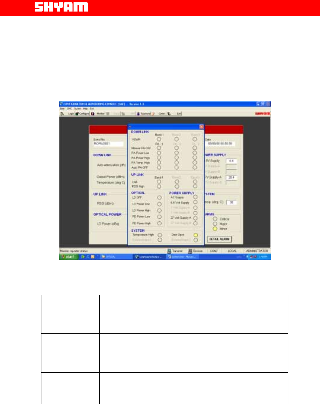
Figure 9: SBROU Alarms Monitoring
f) Alarms-SBOU (Refer Figure 9)
Alarm Observed Detail
PA OFF DL
(Manual) When the user sets PA ON / OFF command as OFF, alarm will be
generated.
PA OFF DL (Auto) When the system sets the PA OFF, alarm will be generated.
PA Power High DL When PA power exceeds the limit set by the user, alarm will be generated.
PA Power Low DL When PA power goes lower than the limit set by the user, alarm will be
generated.
PA Temperature
High It indicates that the temperature has exceeded the limits.
LNA UL LNA failure is indicated.
Laser Diode OFF Failure of Laser Tx power is indicated.

All Rights Reserved Shyam Telecom Limited Page
19 / 41
Next Generation
Signal Enhancement
LD Power Low It indicates that the LD power has gone below the set limit.
LD Power High It indicates that the LD power has exceeded the set limit.
PD Power Low It indicates that the PD power has gone below the set limit.
PD Power High It indicates that the PD power exceeded the set limit.
Power Supply Failure of AC mains, 5.5 V DC & 27 VDC are indicated through separate
LEDs.
VSWR Alarm When antenna port is open or mismatch, alarm will be generated.
Door Open When the door of the outdoor system is open, alarm will be generated. It is
applicable to SBROU for outdoor application.
Minimum monitoring interval is 3 seconds i.e. after every 3 seconds data on
the monitoring window will be refreshed.
For Alarm
A red indication is present.
A green indication is for No alarm.
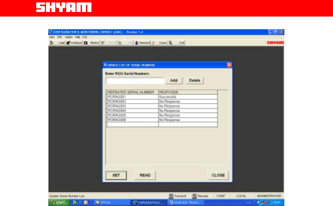
It is possible to have access to any of the SBROUs (Refer Figure 10) from
MOU trough ASK modem and all the functions like, configuration, monitoring
Status & alarms can be carried out. MOU can be accessed through remote
external modem (optional) for above functions.
All Rights Reserved Shyam Telecom Limited Page
20 / 41
Next Generation
Signal Enhancement
Figure 10: Selection of SBROU for Status & Alarm Monitoring
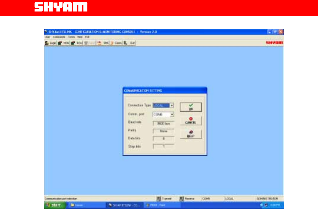
III) Communication Setting [Figure 11]
It is possible to establish communication with MOU & ROU through the
software incorporated in the system.
i. Local Connection
In this type of connection, user computer COM Port and system’s
USB port are connected directly using cable. Proceed as under:
• Click the “COMM.” on the command bar to display the
COMMUNICATION window.
• Select the Connection Type as “LOCAL”
• Select the computer’s Comm. Port where the repeater is
connected.
• Click “OK”.
All Rights Reserved Shyam Telecom Limited Page
21 / 41
Next Generation
Signal Enhancement
Figure 11: Communication Settings
ii. Remote Connection
In this type of connection, User communicates from/to remote
location with the system using wireless External Modem.
To connect:
• Click the “COMM.” on the command bar to display the
COMMUNICATION window.
• Select the Connection Type as “REMOTE”.
• Select the computer’s Comm. Port where the GSM Modem is
connected.
• Click “OK”.
• Now click the DIALUP on the command bar to display the
DIALUP window.
• Enter / Select the repeater phone number.
• Click the “DIAL” and wait (maximum 60 seconds) for
connection.
A message “CONNECTED” will appear on the screen after the wireless
Connection is established.
All Rights Reserved Shyam Telecom Limited Page
22 / 41
Next Generation
Signal Enhancement
Click the “DISCONNECT” on the DIALUP window to disconnect
remote communication with the system.
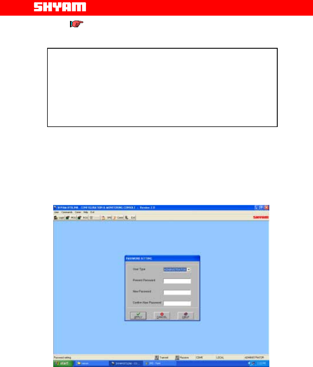
IV) SECURITY [Figure 12]
Password Setting
Select Password setting from Security menu to change the existing
Password. If logged in user is SUPERVISOR, the password for
SUPERVISOR only, can be changed.
The ADMINISTRATOR can perform all the functions including change
of the password for ADMINISTRATOR & SUPERVISOR.
Figure 12: Password Setting
CAUTION
When the communication between repeater & PC/Laptop is in progress
through USB:
• Do not remove cable from the USB port.
• Do not switch off the repeater.
In case the communication is not required any more, click at EXIT before
removing cable from USB port to avoid hanging of the PC/Laptop. In case
the PC/Laptop goes in to hanging mode, it has to be restarted after
closing/switching OFF & ON the repeater.

All Rights Reserved Shyam Telecom Limited Page
23 / 41
Next Generation
Signal Enhancement
6.3. Block Description
Main constituents of the system are:
I) Master Optical Unit (MOU)- Figures 13 & 14
The MOU is installed at the indoor location close to the BTS. In the DL
path, the received RF signals from the BTS are fed to the MOU, which
converts the RF signals to a stream of optical signals to be applied to the
optical fiber for transmission to SBROUs installed at different locations.
The optical signals between MOU & each of the SBROUs are propagated
on two single mode fibers.
In the UL path, the optical signals received from each of the SBROUs are
converted back to the RF signals in the preset frequency band for
application to the BTS.
The connectivity between the MOU and the BTS is through low loss RF
cable via a directional coupler.
Modules in the MOU
a) Duplexer: It is provided in the RF path interfacing BTS for providing
isolation between the DL & UL frequency bands (1710 MHz to 1755
MHz & 2110 MHz to 2155 MHz).
b) Optical Transmitter Unit (OTX): It receives RF signals in the preset
frequency band in the DL path & converts the same to the optical
signals in 1310 nm wavelength at a level of –1.5dBm±1dBm for
application to the optical fiber. One OTX unit is equipped in MOU for
BTS Link-104 & two OTX units are equipped for BTS Link-108.
c) Optical Splitter 1:4 Unit: As indicated earlier, one MOU supports 4
SBROUs or 8 SBROUs at different locations, the optical signals from
each OTX are split in this unit in to 4 in case of BTS Link-104. Two
splitters shall be equipped in case of BTS Link-108.
d) Optical Receiver Unit (ORX): 4 ORX or 8 ORX (depending on the
version) units are equipped in the MOU and each of them receives
optical signals in 1550 nm wavelength from the SBROU in the UL
path. Stream of out put optical signals from each ORX unit is
converted in to RF signals for application to BTS at the desired
power.
e) Power Supply Unit (PSU): The unit gets input of –48 V DC or 100 to
240 V AC (depending on option) for deriving different DC voltages
required for other active units in the MOU.
f) Gain Module: It is available after ORX in the UL path for making RF
signals available for application to the BTS.

All Rights Reserved Shyam Telecom Limited Page
24 / 41
Next Generation
Signal Enhancement
g) Supervisory & ASK Modem: Supervisory and ASK modem enable
the monitoring the status of MOU & SBROUs at different locations
and the information can be extracted through USB port interface
available in the front panel.
II) Optical Fiber & Patch Cords: It is very important part of the system,
which connects MOU with SBROU through two fibers. Two single mode
optical fibers are needed between the MOU and each SBROU. Fiber
carrying signals from the specific SBROU is terminated at the
corresponding ORX in the MOU likewise; fiber carrying signals for
specific SBROU is terminated at one of the splitter ports.

All Rights Reserved Shyam Telecom Limited Page
25 / 41
Next Generation
Signal Enhancement
III) Single Band Remote Optical Unit (SBROU): It houses the following
modules:
a) Optical Receiver Unit (ORX): One such unit is provided in the
SBROU, which receives the optical signals in the 1310 nm
wavelength in the DL path from MOU and converts the same to RF
signals in the preset frequency band.
b) Power Amplifier (PA): The PA unit is responsible for generating the
desired RF power for application to the server antennas. It is provided
in the DL path and the gain of the amplifier is set in accordance with
RF power required.
c) Duplexer: It is provided to isolate the DL & UL RF signals. It
interfaces with the server antenna.
d) Low Noise Amplifier (LNA): It is provided in the UL path after the
Duplexer to provide the amplification to the RF signals.
e) Optical Transmitter Unit (OTX): It receives RF signals in the preset
frequency band in the UL path & converts the same to the optical
signals in 1550 nm wavelength at a level of +4±1dBm for application
to the optical fiber. One OTX unit is equipped in ROU.
f) Power Supply Unit (PSU): One PSU is equipped in the ROU for
deriving DC voltages required for operation of different devices, it gets
AC in the range of 140-270 V, 47/63 Hz.
g) Supervisory & ASK Modem: Supervisory and ASK modem enable
the monitoring the status of MOU & SBROUs at different locations
and the information can be extracted through USB interface.
h) Gain Modules: One is provided between ORX and PA in the DL path
for enabling generation of the desired RF band. Another one is
provided with the OTX unit.
iv) Server Antenna: The RF signals from SBROU are distributed to the
mobile users through server antenna mounted at the appropriate spot
from where the intended area can be provided with coverage. For
indoor coverage, a set of server antennas at different spots at indoor
locations is installed. For outdoor coverage, omni antenna is mounted
at outdoor location. In both cases, antenna should be of appropriate
gain & required frequency band.

All Rights Reserved Shyam Telecom Limited Page
26 / 41
Next Generation
Signal Enhancement
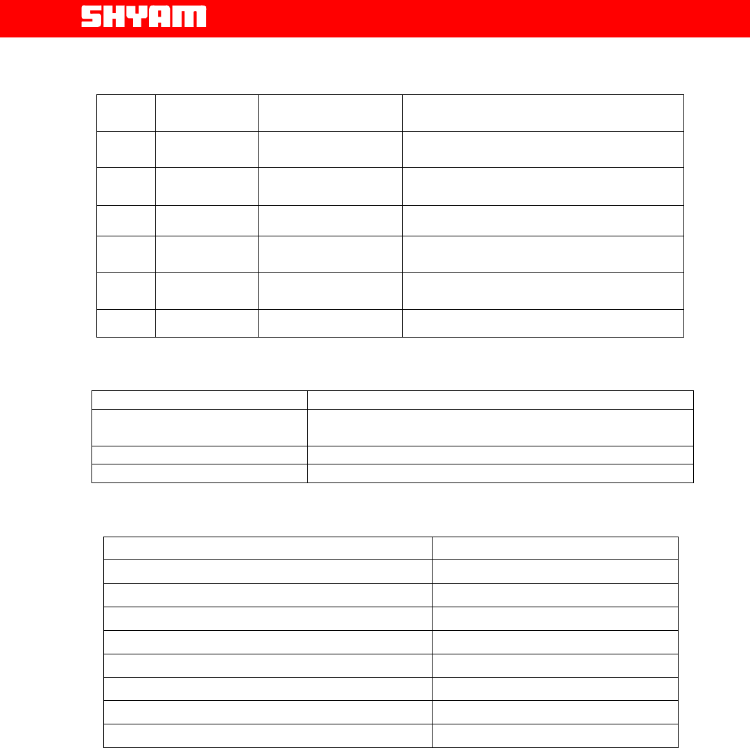
7. BTS LinK-104/108 Repeater Specifications
7.1. Electrical Specifications-RF & Optical
S.NO. Parameter Specifications for MOU
Specifications for
SBROU
1. Optical
Wavelength (TX) 1310 nm 1550 nm
2. Optical
Wavelength (RX) 1550 nm 1310 nm
3. Frequency Band
2110 MHz to 2155 MHz
(DL)
1710 MHz to 1755 MHz
(UL)
2110 MHz to 2155 MHz
(DL)
1710 MHz to 1755 MHz
(UL)
4. Optical Power TX
–1.5dBm±1dBm +4dBm±1dBm
5. RF power options
in DL path - +40dBm±1dBm
6. Impedance at RF
ports 50 Ohms 50 Ohms
7. Spurious
Emission < -36dBm @ 9 KHz to 1
GHz, <-30dBm @ 1 GHz
to 12.75 GHz
< -36dBm @ 9 KHz to 1
GHz, <-30dBm @ 1 GHz
to 12.75 GHz
8. System Noise
figure ----------------5dB max. --- ------------------------------
9. Group delay
without fiber ---< 0.5 microseconds----
-------------------------------
7.2. Electrical Specification Power Requirement
S.NO. Parameter Specifications for MOU Specifications for ROU
1. Power
Supply -48 V DC 140-270 V AC, 47/63 Hz
2 Power
consumption
(Approx.)
60 watts (Fully equipped) 200 watts
7.3. External Electrical/Optical Interface
S.NO. Parameter Specifications for MOU Specifications for ROU
1. RF Port N-type N-type
2. Optical Port
FC-PC FC-PC
All Rights Reserved Shyam Telecom Limited Page
27 / 41
Next Generation
Signal Enhancement
7.4. Mechanical Specification
S.NO. Parameter Specifications
for MOU Specifications for ROU
1. Dimensions
(w x h x d)
485x400x135 mm
(19x16x5 inches) 700x385x210 mm (27x15.2x8inches)
2. Weight
(Approx.)
12 Kg. (26 lbs.) 25 Kg. (55 lbs.) +37dBm
3. Housing Metal Housing for
Indoor application Metal Housing for outdoor application
4. Grounding
Connection
- Bolt (Outdoor Housing)
5. Housing
Color
Grey Grey
6. Cooling Convection Convection
7.5. Environmental Specification
Conditions Specification
Operating Temperature -20oC to +550C (-40F to +1310F)
Storage Temperature -300C to +800C (-220F to +1760F)
Enclosure Outdoor application requirement
7.6. Contents of Delivery
ITEMS
QUANTIT
Y
Repeater BTS Link-104/108 MOU 1
Repeater BTS Link-104/108 SBROU As per requirement
PC interface cable for USB port
As per requirement
Power cable with 3 pin pug
As per requirement
Operation & Installation manual
As per requirement
CD containing th
e application software
As per requirement
Wireless Modem (Optional)
As per requirement
Mounting Clamps with Nuts
-
bolts
As per requirement
7.7. Safety Precautions-Handling Optical Equipment
Special care has to be taken while handling the optical equipment to avoid
damage not only to the equipment but also to the technicians/Engineers
who are handling the equipment. MOU and SBROU are equipped with
Lasers; direct exposure to the human eyes must be avoided. Though the
Lasers used in the equipment are of low power and are classified as class
III B (norm EN60825) even then enough care needs to be taken to avoid
exposure.

All Rights Reserved Shyam Telecom Limited Page
28 / 41
Next Generation
Signal Enhancement
Optical connectors for single mode fibers are designed for sub micron
tolerances.
Even a small particle of dust shall cause excessive loss & adversely affect
the performance:
For safety reasons & optimum performance, following points need attention:
• The optical connectors should never be left in open condition to avoid
entry of dust/moisture etc.
• When working with the optical connectors or the optical fiber, check at
each end that both optical transmitters are switched off.
• The connectors should be cleaned regularly with ethyl alcohol and
tissue paper; the tip should not be touched with bare hands.
• The connectors are very delicate in nature therefore proper aligning
without applying excessive force should carry out removal & insertion.

All Rights Reserved Shyam Telecom Limited Page
29 / 41
Next Generation
Signal Enhancement
8. Installation
8.1. Preparation Sheet-Pre Installation
1. General
Application: Outdoor
Service Band: AWS
Frequency Band DL: 2110 MHz to 2155 MHz
Frequency Band UL: 1710 MHz to 1755 MHz
Number of SBROUs installed at different sites:
2. Master Unit
Parameter Remarks
BTS power
Estimated Feeder Loss between BTS & Coupler
Estimated Coupling loss (in coupler)
Estimated Feeder loss between coupler & Master
unit
Estimated Input RF power in DL to Master unit
Arrangement for termination of optical fibers
Optical power in link path (DL)
Estimated RF power in UL
3. Optical Path
Parameter Remarks
Optical Fiber length between MOU-ROU 1……4/8
Estimated optical loss between MOU-ROU 1……4/8
Estimated optical signal level at each ROU input in
DL
Estimated optical signal level at MOU from each of
the SBROUs
4. Remote Unit (s)
Parameter Remarks
Proposed attenuation in DL
Proposed attenuation in UL
Arrangement for termination of optical fibers
Desired power at server antenna in DL
Proposed gain setting in DL
Date: …………. Prepared by……………………….
Site Address: ……………..

All Rights Reserved Shyam Telecom Limited Page
30 / 41
Next Generation
Signal Enhancement
8.2. MOU Installation
As mentioned earlier in this document, the MOU is placed at indoor location,
which is close to the BTS from where the signals are to be fed through
directional coupler.
Following points need consideration:
• The MOU should be installed at the spot where optical fiber ends are
terminated and is a secured place where unauthorized access is
avoided.
• The length of RF coaxial cable route from MOU to the BTS via
directional coupler should also not be excessive & sharp bends are to
be avoided to minimize losses.
• MOU is operated from –48 V DC, this supply either from battery or from
a separate power pack operated through AC should be available.
• The site should be easily accessible by the maintenance staff.
• The environment should be free from excessive moisture, chemical
fumes and ultra-violet radiations.
• The environment is not subjected to any Automobile Ignition noise,
Generator noise etc.
Installation Tools
a. Standard wrenches/screwdrivers/cable stripper/cable cutter/pliers
set for installing the system and antennas. (Refer to the
manufacturer’s recommendations for installing the antennas).
b. RF cable connecting tool for fixing connectors.
c. Multi-meter.
d. Optical power Meter.
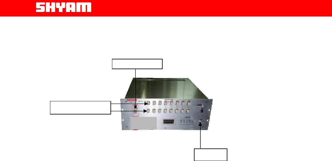
Termination/Connections at MOU: Connections as detailed below need to
be carried out:
• Optical fibers for connectivity to SBROUs at different locations are
required to be terminated on MOU. Two fibers are needed for each
of the SBROUs.
• RF connection for transfer of signals from/to BTS.
• Power connection for extending –48 V DC to MOU.
All Rights Reserved Shyam Telecom Limited Page
31 / 41
Next Generation
Signal Enhancement
Figure 16: Termination at MOU
Important:
• Continuity/short circuiting of RF coaxial wherever used should
be checked before making connections.
• Continuity of each fiber to the respective ROU should be
ensured.
• The system should not be switched ON till the installation is
completed and settings in the system are made.
• No optical connector should be left open.
Commissioning MOU:
Preliminary verify the correct operation of MOU:
• Visual inspection of MOU cards before use, for any mechanical
or component damage.
• Insert the cards in the designated slot only.
• Switch-ON the MOU sub rack.
• Measure the optical power at each of the optical ports in DL.
• Verify the LED status through CMC software.
Important:
a. Continuity/short circuiting of RF wherever used should be checked
before making connections.
b. Continuity of each fiber to the respective SBROU should be
ensured.
c. The system should not be switched ON till the installation is
completed and certain settings for the system is made.
d. No optical connector should be left open.
USB Port
To BTS Coupler
Opti
cal Tx & Rx

All Rights Reserved Shyam Telecom Limited Page
32 / 41
Next Generation
Signal Enhancement
8.3. Optical Fiber Laying
The connectivity between the MOU and SBROUs at different sites is through
optical fibers. In case the fibers are not available, the laying of optical fiber
cable has to be undertaken. Single mode fibers are used for which two fibers
are required between the MOU and each of the SBROUs.
Depending on the situation, the type of optical fiber cable could be of aerial
type or of buried type. In aerial type, the OFC is firmly fixed/clamped on the
poles/pillars in the open atmosphere and such cables are normally armored
to provide adequate protection/strength. The advantage of using such able is
that the installation job can be completed in less time. However, the cost of
the cable is higher. Whereas the buried type, the OFC is placed in pipes
which are laid underground.
A variety of cable designs are available to meet the requirements of different
installations. Some of the designs are given below:
• Loose tube construction: The fiber lies loosely inside a surrounding
plastic tube so that it can adjust itself when the cable is bent; micro
bending is almost completely eliminated by this technique. Loose tube
cables are preferred for long distance links and for almost all outdoor
applications.
• Tight buffer construction: The buffered fiber is completely enclosed
in a cushioning material (secondary coating up to an external diameter
of 900 micro meters) to improve crush resistance and vibration
isolation, minimizing micro bending. Tight buffer cables are usually
adopted for outdoor applications because they offer small cross-section
dimensions and small bending radius.
Termination of fibers on MOU and SBROU
Under the normal circumstances, two fibers are utilized for connecting
MOU to a particular SBROU, one for the UL & other for the DL path.
Every fiber must be labeled in order to indicate the connection particulars
& route.
Sharp bends on the pigtails are to be avoided while making connections.
The optical connectors must be cleaned thoroughly to avoid entry of dust
and obstructions to the optical signals.
The guidelines for OFC laying are:
• The exact route may be decided before starting the laying work.
• Extra length of OFC may be kept for future use at each end.
• The OFC should be free from all optical connectors and should be
sealed at both the ends at the time of laying.
• Sharp bends, extra pressure and pull should be avoided during
laying to avoid damage to the fibers.
• Proper splicing should be carried out for minimum splice losses.

All Rights Reserved Shyam Telecom Limited Page
33 / 41
Next Generation
Signal Enhancement
• All technical specifications from the OFC supplier should be
followed.
• The termination of OFC at each end should be done at FDFs, which
should be located close to the equipment.
• Connection between the OFC (terminated at FDF) and the
equipment should be carried out through optical jumpers with FC-
PC connectors.
8.4. Installation-SBROU
Outdoor Coverage: Following points need to be considered
• Availability of AC mains in the range 140-270V 47/63 Hz for energizing
the SBROU
• It is installed at outdoor site, so it should be in the secured area where
unauthorized access is avoided.
• The site should be close to the fiber termination point.
• It is mounted either on pole or on the wall; enough space should be
available for opening the unit door for testing & maintenance staff.
• Outdoor antenna with proper frequency band & gain is installed outside
preferable at a height for distribution of signals to the mobile users.
Termination/Connections at SBROU: Connections as detailed below need
to be carried out:
• Optical fibers for connectivity to MOU. Two fibers are needed for
each of the SBROUs.
• RF connection for transfer of signals from/to antennas.
• Power connection to the AC mains.
• Grounding of the unit.
Commissioning SBROU:
• After making the desired connections, Switch “ON” The power
supply.
• Check the LED status at ROU.
• Measure the Optical Output Power. It should be +4±1dBm.
• If any Parameter is not within the specified limits, check the
connections and observe for the alarm.

All Rights Reserved Shyam Telecom Limited Page
34 / 41
Next Generation
Signal Enhancement
8.5. Dos & Don’t Dos
1. The BTS-104/108 system is comprised of two independent units viz.
Master Optical unit & Single Band Remote Optical Unit; the site selection
should be made with great care for maximum efficiency.
2. The site(s) should be accessible for maintenance purposes.
3. Arrangement is to be made to avoid unauthorized access to the system.
4. Proper grounding of the outdoor units is required to be done to avoid
damage to the system.
5. The housings for outdoor applications must be waterproof.
6. Stable power supply for all units should be ensured.
7. The route of Cables to/from antennas should be short to limit the cable
losses and should be free from sharp bends & kinks.
8. Local standard of cabling should be followed.
9. Route of cable from antenna to the system should be secured to avoid
damage and connections have to be made water tight to prevent the entry
of water in the equipment.
10. There should be adequate separation between the antenna system and
power lines.
11. The Master unit draws RF input from BTS; its level should not be
excessively high for satisfactory performance.
12. The optical fiber termination should be carried out with care and no optical
port left open when the system is ON.
13. Bending of optical fiber cable at acute angles must be avoided
14. The estimation of coverage area should be confirmed.
15. The system should be configured for normal traffic after actual
measurement of:
a) RF power in the DL
b) RF power in the UL
16. Feedback regarding performance of the system must be obtained from the
user.

All Rights Reserved Shyam Telecom Limited Page
35 / 41
Next Generation
Signal Enhancement
8.6. Checklist-Post Installation
Service Band: AWS
Frequency Band DL: 2110 MHz to 2155 MHz
Frequency Band UL: 1710 MHz to 1755 MHz
A. Coupler Installation
S.NO. Point(s) To Be Verified Remarks
1. 30 dB coupler installed on BTS main antenna
feeder
2. Type N connector closer to antenna terminated
with 50 Ohms
3. Type N connector closer to BTS connected to
donor cable
4. BTS operating normally with coupler installed
5. Coupler weatherproof
B. Master Unit Installation
S.NO. Point(s) To Be Verified Remarks
1. Grounding of the unit
2. Cable from coupler terminated at donor (BTS) port
3. Termination of optical fibers for different ROUs &
no optical fiber port is left open. Two fibers are
provided for each ROU.
4. -48 V DC cable connected to the Master unit
5. RF Cable protection ensured and outdoor
connections are waterproof
6. Precautions against excessive bending of optical
cable.
7. Labels showing cautions displayed
C. Master Unit Setup
S.NO. Point(s) To Be Verified Remarks
1. Master unit switched ON
2. Any error/alarm observed
3. RF signal strength in DL
4. Transmitting optical signal strength at relevant optical
port for each ROU
5. Received optical signal strength at relevant optical
port from each ROU
6. Loss for optical signals between MOU and each of
the ROUs is within limits.
7. RF power set in UL.
8. Attenuation inserted in UL.
D. Remote Unit Installation
S.NO. Point(s) to be verified Remarks
1. Ensure termination of optical fibers at optical Tx & RX
ports.
2. Grounding of the unit
3. RF cable connected between RF port and server
antenna.

All Rights Reserved Shyam Telecom Limited Page
36 / 41
Next Generation
Signal Enhancement
4. Cable to server antenna connected to server antenna
port
5. Mains cable connected to the Remote unit
6. RF Cable protection ensured and outdoor
connections are waterproof
E. Remote Unit Setup
S.NO. Point(s) To Be Verified Remarks
1. Remote unit switched ON
2. Any error/alarm observed
3. Received optical signals at RX port
4. Attenuator inserted for desired RF power
5. RF power set
6. Optical signal strength at TX port
7. Remote unit secured.
Any Other Remark/Comment:
Date Of Installation: ------------------------ Repeater ID: -------------------------------
Site Address: --------------------------------------------------------------
Name of the Installer: -----------------------------------------------------

All Rights Reserved Shyam Telecom Limited Page
37 / 41
Next Generation
Signal Enhancement
9. System Maintenance
9.1. General
The system normally operates without any operator intervention or
maintenance. If, in the unlikely event of a unit failure, the field replaceable
units (antenna unit, cables) should be checked for faults and the system
restored. The faulty unit can be removed and replaced with a spare while
the rest of the system is still operating. Soldering or local repair of the
modules should be avoided from better maintenance point of view. Faulty
module/unit should be replaced with genuine spares from Shyam Telecom
Limited only.
The power supply of the faulty unit should be isolated from AC mains and
DC power before any module is replaced. In the event of a system
malfunction, the status of the antenna systems should be checked as well
as the continuity of the cabling before replacing any modules within the
unit.
9.2. Preventative Maintenance
The BTS Link-104/108 does not require any preventative maintenance.
However, some of the common observations as tabulated below are
possible:
Observation Remark
No communication
between MOU & ROUs
a) Check if the MOU is ON. If it is not ON, check the
availability of –48 V DC for MOU. Make sure that –
48 V is available.
b) Check the alarms, if Laser diode/photo diode failure
is indicated. Verify functioning of OTX unit by
replacing with working unit. Also clean the optical
connectors wherever provided.
c) Check the optical power at each port connected to
the SBROUs. If it is available at each of the ports,
check the optical connectivity between MOU and
SBROUs.
RF power high in DL at
ROU
Check for the indication for alarm and insert an
additional attenuator to reduce the RF power.
RF power low in DL at
SBROU
Check for the indication for alarm and adjust the
attenuator to enhance the RF power.
Power high UL at MOU Reduce the level by inserting additional attenuator.
RSSI LOW/HIGH DL at
MOU
Adjust the attenuator in order to get rid off the alarm.
Also check the RF cable between the antenna and the
MOU.
Photo-diode failure at
MOU
It indicates a problem in the ORX unit. Check & verify
the ORX unit, if required replace it.

All Rights Reserved Shyam Telecom Limited Page
38 / 41
Next Generation
Signal Enhancement
FCC Statement:
FCC ID:S3CBTSLINK1048
This device complies with Part 2, 27 of the FCC Rules. Operation is
subject to the following two conditions: (1) this device may not cause harmful
interference and (2) this device must accept any interference received, including
interference that may cause undesired operation.
IC Statement:
Trade Name: SHYAM BTS Link-104/108 Repeater
Model No.: 104/108
IC: 5751A-BTSLINK1048
This device complies with RSS-131, RSS-102 of the IC Rules.
Warning
Changes of modifications not expressly approved by the manufacturer could void
the user’s authority to operate the equipments.
Antenna Information:
This device has been designed to operate with the antennas listed below, and having a
maximum gain of 16dB. Antennas not included in this list or having a gain greater than
16dB are strictly prohibited for use with this device. The required antenna impedance is
50 ohms.
Antenna (or equivalent) list:
1) Patch Panel Antenna ,16 dbi for outdoor installation
2) Yagi Antenna 12 dbi for outdoor installation
3) Patch Panel Antenna 9 dbi for indoor IBS installations
4) Omni Antenna 2 dbi for indoor IBS installations
To reduce potential radio interference to other users, the antenna type and its gain
should be so chosen that the equivalent isotropically radiated power (e.i.r.p.) is not more
than that permitted for successful communication.
WARNING! This equipment complies with FCC & IC radiation exposure
limits set forth for an uncontrolled environment. This transmitter must not
be co-located or operating in conjunction with any other antenna or transmitter.
For mobile or fixed location transmitters, the minimum separation distance is
greater than 120 cm (indoor server antenna) and 260cm (outdoor server
antenna), even if calculations that the MPE distance would be less.
All Rights Reserved Shyam Telecom Limited Page
39 / 41
Next Generation
Signal Enhancement
For Technical Support, please contact at any of the following addresses:
For Americas
Shyam Telecom Inc.
6, KILMER ROAD, SUIT D,
EDISON, New Jersy-08817 (USA)
For Europe
Shyam Telecom GmbH.
Frohsinnstrasse 16, 63739 Aschaffenburg, Germany
Tel: + 49-6021-45901-0 Fax: + 49-6021-45901-29
For ASEAN & Others
Shyam Telecom Ltd.
246, Phase IV, UDYOG VIHAR,
GURGAON – 122015 (INDIA)
Tel: +91-124-4311600 FAX: +91-124-4018117
Email:
contact@shyamtelecom.com