Shyam Telecom DB5R33-8501900 Dual Band Repeater Cellular-850 + PCS-1900 User Manual User s manual for
Shyam Telecom Inc. Dual Band Repeater Cellular-850 + PCS-1900 User s manual for
Contents
- 1. Users Manual 1
- 2. Users Manual 2
- 3. Users Manual
Users Manual 1
Next Generation
Signal Enhancement
RF / DBR Series
O
OP
PE
ER
RA
AT
TI
IO
ON
N
&
&
I
IN
NS
ST
TA
AL
LL
LA
AT
TI
IO
ON
N
M
MA
AN
NU
UA
AL
L
. Page
DDBB55R
R
(
(Dual Band)
850 Cellular & 1900 PCS For Outdoor Applications
October 2007
Proprietary Information
The information contained herein is proprietary to Shyam Telecom Limited.
Unauthorized access, copy and replication are prohibited. This document must
not be copied in whole or part by any means or it shall not be disclosed o
r
divulged to any third Party without the prior written consent of Shyam Telecom
Limited.
All Rights Reserved Shyam Telecom Limited 1/35

Next Generation
Signal Enhancement
Contents
1. Document History.........................................................................................4
2. Disclaimer......................................................................................................5
3. Safety Instructions and Warnings...............................................................5
3.1. Personnel Safety....................................................................................5
3.2. Equipment Safety...................................................................................5
3.3. Electrostatic Sensitivity ..........................................................................6
4. Introduction...................................................................................................7
4.1. Purpose .................................................................................................7
4.2. Scope.....................................................................................................7
4.3. Definitions ..............................................................................................7
4.4. References ............................................................................................8
4.5. General ..................................................................................................8
5. Functional Description Of DB5R Dual Band Repeater...............................9
5.1. General Description ...............................................................................9
6. To Get started-Basic Software Control Of the Repeater..........................13
6.1. General ................................................................................................13
6.2. Terminal Set-up ...................................................................................13
6.3. Modules In DB5R-Description..............................................................20
7. DB5R Repeater Specifications...................................................................24
7.1. Electrical Specifications-RF .................................................................24
7.2. Electrical Specification Power Requirement ........................................24
7.3. External Electrical Interface .................................................................24
7.4. Mechanical Specification .....................................................................24
7.5. Environmental Specification.................................................................25
7.6 Contents of Delivery............................................................................25
8. Installation...................................................................................................26
8.1. Preparation Sheet- Pre Installation ......................................................26
8.2. Engineering Consideration...................................................................27
8.3. Installation Tools..................................................................................29
8.4. Installation Procedure ..........................................................................29
8.5. Repeater Gain Settings........................................................................30
8.6. Commissioning ....................................................................................31
8.7. Dos & Don’t Dos ..................................................................................31
8.7.Checklist – Post Installation ..................................................................33
9. System Maintenance...................................................................................34
. Page
All Rights Reserved Shyam Telecom Limited 2/35

Next Generation
Signal Enhancement
9.1. General ................................................................................................34
9.2. Preventative Maintenance ...................................................................34
. Page
All Rights Reserved Shyam Telecom Limited 3/35

Next Generation
Signal Enhancement
1. Document History
Document
Number Document
Name Document
date Author Edited
by Approved by Revision
DB5R
Dual
Band
Repeater
October
2007
Revision Revised Section Date/Sign
Intentionally Left Blank
. Page
All Rights Reserved Shyam Telecom Limited 4/35

Next Generation
Signal Enhancement
2. Disclaimer
Every attempt has been made to make this material complete, accurate, and
up-to-date. Users are cautioned, however, that Shyam Telecom Limited
reserves the right to make changes without notice and shall not be
responsible for any damages including consequential, caused by reliance of
the contents presented, including, but not limited to, typographical,
arithmetical, or listing errors.
Product name(s) referenced in this document may be trademarks or
registered trademarks of their respective companies, and are hereby
acknowledged.
In areas with unstable power grids (mains) all repeaters must be installed with
a voltage regulator ensuring a constant voltage level at the repeater power
input. A maximum voltage deviation should remain within the input range to
the repeaters for warranty purposes.
All antennas must be installed with lighting protection. Damage to internal
modules, as a result of lightning is not covered in the warranty.
3. Safety Instructions and Warnings
3.1. Personnel Safety
Before installing or replacing any equipment, the entire manual should be
read and understood. The user needs to supply the appropriate AC power to
the Repeater. Incorrect AC power settings can damage the repeater and may
cause injury to the user.
Throughout this manual, there are "Caution" warnings, "Caution" calls
attention to a procedure or practice, which, if ignored, may result in injury or
damage to the system or system component or even the user. Do not
perform any procedure preceded by a "Caution" until the described
conditions are fully understood and met.
3.2. Equipment Safety
When installing, replacing or using this product, observe all safety
precautions during handling and operation. Failure to comply with the
following general safety precautions and with specific precautions described
elsewhere in this manual violates the safety standards of the design,
manufacture, and intended use of this product. Shyam Telecom Limited
assumes no liability for the customer's failure to comply with these
precautions. This entire manual should be read and understood before
operating or maintaining the repeater system.
. Page
All Rights Reserved Shyam Telecom Limited 5/35
Next Generation
Signal Enhancement
CAUTION
Calls attention to a procedure or practice which, if not followed, may result in
personal injury, damage to the system or damage to individual components. Do
not perform any procedure preceded by a
CAUTION until described conditions are fully understood and met.
WARNING! This equipment complies with FCC & IC radiation exposure limits
set forth for an uncontrolled environment. This transmitter must not be co-
located or operating in conjunction with any other antenna or transmitter.
The unit with server antenna must be installed to provide minimum 110 cm
separation distance between the server antenna and the body of user or near
by person. The donor antenna used for this transmitter must be fixed-
mounted on outdoor permanent structures with a separation distance of at
least 1.5 meters from all persons during normal operation.
The RF electric performance of the repeater conforms to FCC requirement of
the inter modulation and spurious emission. It avoids interference problems.
3.3. Electrostatic Sensitivity
CAUTION
ESD = ELECTROSTATIC DISCHARGE SENSITIVE DEVICE
Observe electrostatic precautionary procedures.
Semiconductor transmitters and receivers provide highly reliable performance
when operated in conformity with the intentions of their design. However, a
semiconductor may be damaged by an electrostatic charge inadvertently
imposed by careless handling.
Static electricity can be conducted to the semiconductor chip from the centre
pin of the RF input connector, and through the AC connector pins. When
unpacking and otherwise handling the Repeater, follow ESD precautionary
procedures including the use of grounded wrist straps, grounded workbench
surfaces, and grounded floor mats.
. Page
All Rights Reserved Shyam Telecom Limited 6/35

Next Generation
Signal Enhancement
4. Introduction
4.1. Purpose
The purpose of this document is to describe the electrical and mechanical
specifications, operation and maintenance of the DB5R Dual Band Repeater.
4.2. Scope
This document is the product description of the Shyam DB5R Dual Band
Repeater for outdoor application.
4.3. Definitions
AGC Automatic Gain Control
ALC Automatic Level Control
APC Automatic Power Control
BCCH Broadcast Control Channel
BTS Base Transceiver Station
BSEL Band Selective
CDMA Coded Division Multiple Access
CMC Configuration & Monitoring Console software
CMB Combiner Unit
CSEL Channel Selective
DCS Digital Communication System
DL Downlink signal (from base station via repeater to
mobile station)
EGSM Extended Global System for Mobile Communication
ETSI European Telecommunications Standard Institute
GSM Global System for Mobile communication
LAC Location Area Code of the BTS site
LED Light Emitting Diode
LNA Low Noise Amplifier
LO Local Oscillator
MS Mobile Station
MSC Mobile Switching Center
NMS Network Management System
PCN Personal Communication Network
PCS Personal Communication System
PSU Power Supply Unit
RF Radio Frequency
RMS Remote Management System
RSSI Received Signal Strength Indication
RTC Real Time Clock
TACS Total Access Communication System
TDMA Time Division Multiple Access
UL (Uplink) Uplink signal direction (from mobile station via
repeater to base station)
. Page
All Rights Reserved Shyam Telecom Limited 7/35

Next Generation
Signal Enhancement
4.4. References
[1] ETS 300 086.
Radio Equipment and Systems Land mobile service Technical
characteristics and test conditions for radio equipment with an internal or
external RF connector intended primarily for analogue speech.
[2] ETS 300 609-4.
Digital cellular telecommunications system (phase 2): Base Station
Systems (BSS) equipment specification: Part 4: Repeaters.
[3] ETS 300 342-3
Radio Equipment and Systems (RES); Electro-Magnetic Compatibility
(EMC) for European Digital Cellular Telecommunications systems. Base
Station Radio and ancillary equipment and Repeaters meeting phase 2
GSM requirements.
4.5. General
Mobile Communications Systems are planned as cellular systems and each
cell of the base station is required to provide RF coverage over a certain
geographical area as per defined RF power levels. Due to the RF propagation
properties, even using high radiated RF powers or complicated antenna
systems, there are zones within the coverage area where the RF signal
strength from base station remains inadequate for establishing the desired
connectivity to mobile users.
Repeaters traditionally are deployed in the Mobile Communication network to
fill in the “Dead Zones” caused by blocking of signals by geographic
topologies such as mountains, valleys, dense foliage, high rising urban
landscapes and other man-made structures. The distance from the base
station also adversely affects the RF signal strength. The user views
repeaters as a means to extend base station coverage so as to reduce the
number of base stations and thereby accelerate network availability.
Repeater systems are installed after meticulous planning between BTSs and
the mobile users to provide RF coverage in the shadowed regions. Repeater
systems are available for different applications and ultimate choice shall
depend on some of the factors mentioned below:
• Area to be provided with coverage.
• Indoor/outdoor coverage.
• Availability of BTSs in the vicinity.
• Antenna isolation to be achieved.
. Page
All Rights Reserved Shyam Telecom Limited 8/35

Next Generation
Signal Enhancement
5. Functional Description Of DB5R Dual Band Repeater
5.1. General Description
The DB5R Dual Band Repeater System is designed to provide outdoor
coverage and can handle signals in up to five sub bands with 3+2
configuration (maximum) in two of the service bands, used around the World
by various service operators. It provides highly selective amplification in the
pre-set frequency bands. The details of operating service frequency bands
are given below:
S.NO. Service Band DL Frequency (MHz) UL Frequency (MHz)
1. SMR 800 851-866 806-821
2. Cellular 869-894 824-849
3. SMR 900 935-941 896-902
4. EGSM 925-960 880-915
5. GSM 900 935-960 890-915
6. DCS 1805-1880 1710-1785
7. PCS 1930-1990 1850-1910
8. UMTS 2110-2170 1920-1980
The Customer is requested to refer to the packing list giving the details of
frequency band set & the bandwidths of different sub bands equipped in the
repeater (FCC & IC applications only apply for Cellular & PCS band operations).
• The DB5R repeater is designed to provide optimal coverage, the area
covered shall primarily depend on RF power radiated, manmade
structures in the area (high rise buildings), the geographical topologies
and availability of reflecting surfaces.
• The ultimate performance & coverage shall depend on the obstructions
blocking/absorbing of the RF signals by various objects between the
Server antenna of RF repeater and the mobile users.
• The repeater is specifically designed for the Operators who are
allocated frequency spectrum in different service bands and non-
contiguous sub bands are specified.
• The repeater adopts duplex mode and bi-directional amplification for
U/L & D/L signals between the base station and mobile users.
• It receives signals from the BTS through a DONOR antenna (highly
directional outdoor antenna) and distributes the signals to mobile users
after amplification through a set of SERVER antennas (omni/patch
directional) system in the D/L.
. Page
All Rights Reserved Shyam Telecom Limited 9/35

Next Generation
Signal Enhancement
• In the U/L, the signals from the mobile users are picked up by
SERVER antenna and retransmitted to the BTS after amplification.
• The repeater finds applications in tunnels, highways, large size
airports, and open market areas etc. where traffic requirement is high.
• The system can be incorporated with optional Remote Management
System (RMS) which can be used for configuration and monitoring the
status of the link. It helps not only speedy maintenance but remote
configuration also through wireless modem.
The repeater consists of the following modules/units:
• LNA
• Converter modules
• Power amplifiers
• Power supply module
• Duplexer filters for transmit/receive directions
• Supervisory module
• Diplexer Unit for segregating bands
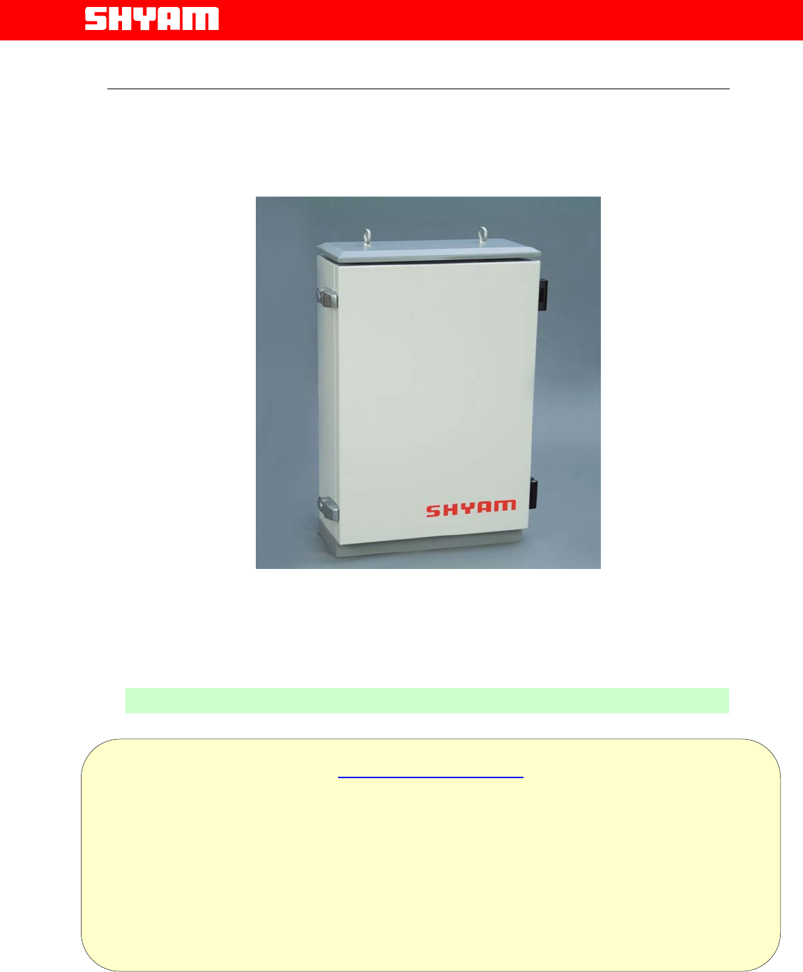
• A metallic case houses the repeater. Arrangement is made for heat
dissipation especially for amplifiers, which generate more heat. The
choice of suitable metal as the case material gives a lightweight design
with good heat conduction and waterproof protection. The housing
conforms to IP65 (NEMA 5) standards.
. Page
All Rights Reserved Shyam Telecom Limited 10/35
Next Generation
Signal Enhancement
. Page
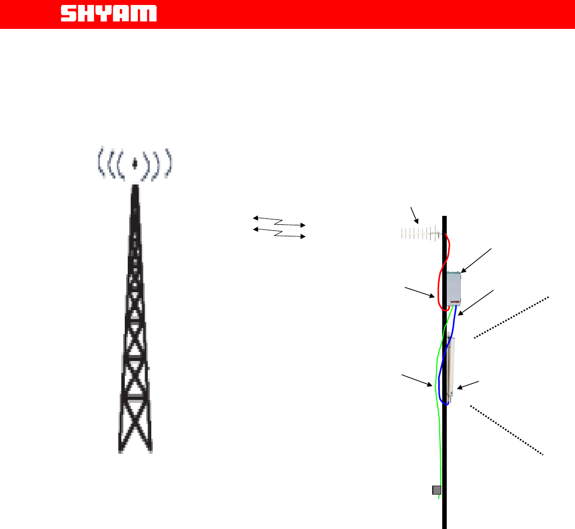
Donor
Antenna
DB5R
Server
Antenna
Area to be served
RF cable from
server
Power supply
cable
RF cable from
donor antenna
BTS
Figure 1: DB5R Repeater-Different Constituents
All Rights Reserved Shyam Telecom Limited 11/35
Next Generation
Signal Enhancement
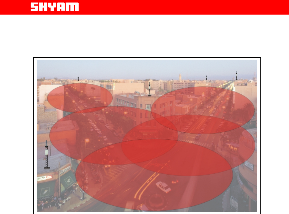
Figure 2: DB5R Repeater - Application in a Urban Area
. Page
All Rights Reserved Shyam Telecom Limited 12/35

Next Generation
Signal Enhancement
6. To Get started-Basic Software Control Of the Repeater
6.1. General
The repeater is equipped with a supervisory module that allows the
monitoring and control of various parameters such as RF power, attenuation,
temperature, status of door and alarm conditions etc.
The communication interface between the local terminal and the control
module can be set up using the Configuration & Monitoring Console software
(CMC), which is an easy to use GUI for simple control and monitoring. This
way, the parameters can be easily observed and adjusted from the display
terminal.
This can be performed either via a terminal (PC/laptop) locally, or via remote
login through the wireless modem (Optional) located in the repeater. USB port
is provisioned in the equipment for connecting PC/laptop.
6.2. Terminal Set-up
The system is delivered with software loaded in order to perform configuration
as per requirement. It also enables monitoring the status. Configuration of
parameters can be carried out locally with the help of laptop / PC connected
to the repeater by means of local USB serial interface or remotely via wireless
modem (Optional) mounted inside the repeater. The laptop/PC should be
loaded with the CMC software available on the supplied CD along with the
USB driver.
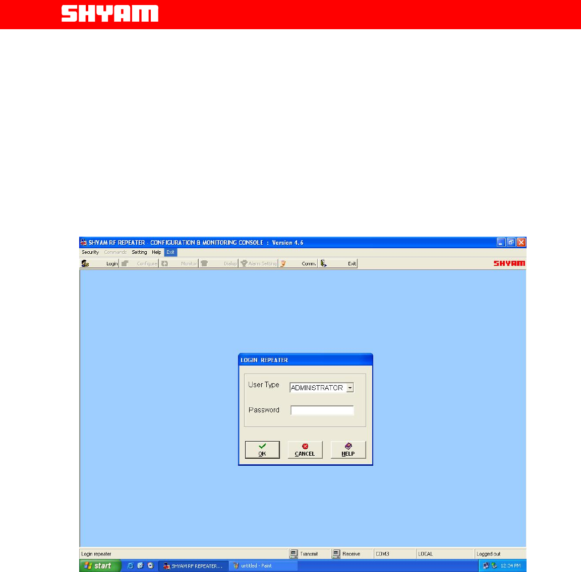
I) LOGIN-Repeater (Figure 3)
After running the repeater Configuration & Monitoring Console (CMC), user
needs to login the repeater, sequence as under, may be followed:
• Click the “LOGIN” on the command bar.
• Select the user type (ADMINSTRATOR or SUPERVISOR).
• Enter the password.
• Finally click the “OK”.
A message “Logged in successfully” will appear on the screen after
successful login. There are two types of users viz. ADMINISTRATOR and
SUPERVISOR. If user logged in as an ADMINISTRATOR, all the functions
can be performed through the CMC. By default, the password for both
users is “SHYAM”.
SUPERVISOR is allowed to perform monitoring of the status & alarms but
no change in configuration is permitted. However, the SUPERVISOR can
change password if so desired.
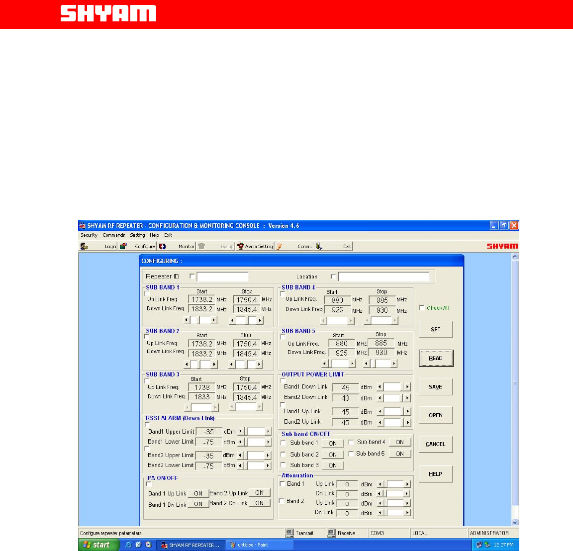
II) CONFIGURATION
Configuring repeater means setting the repeater parameters for operation
as per the requirement at site.
. Page
All Rights Reserved Shyam Telecom Limited 13/35
Next Generation
Signal Enhancement
Click on the command bar to display the configuration window, which
allows access to all the configurable repeater parameters. User can login
for configuration of repeater parameters.
• SET is for updating the repeater parameters.
• READ is for confirming the parameters set during the
configuration.
Information as detailed below, can be configured after the
“Configuration” window is activated:
Figure 3: Login Repeater
a. Repeater ID: User can assign a unique repeater ID to each repeater
installed. Up to 10 characters are allowed in this field. (Figure 4)
b. Repeater Location: User can assign the address of location where
repeater is installed. Up to 30 characters are allowed in this field.
(Figure 4)
c. Sub Bands (UL/DL Frequency Bands) Settings: The frequency
bandwidths of all the five sub bands or loaded sub bands in UL & DL
are defined. (Refer Figure 4)
. Page
All Rights Reserved Shyam Telecom Limited 14/35
Next Generation
Signal Enhancement
d. Thresholds Output Power: Maximum Output Power limit in UL & DL
for both the bands are set. A “PA Power high” alarm will be
generated when PA power exceeds the upper limit. (Refer Figure 4)
e. Thresholds RSSI Limits: Lower and Upper RSSI Limits in DL & UL
paths for both the bands are set. A RSSI High alarm will be generated
when RSSI exceeds the set upper limit, and a RSSI Low alarm will be
generated when RSSI goes below the set lower limit set. Upper range
that can be set varies from -35 to -55dBm. Lower range that can be
set varies from -75 to –95dBm. (Refer Figure 4)
Figure 4: Configuration window
f. Sub band ON/OFF: The equipped sub bands are brought in the ON
mode and others are put in OFF condition.
g. PA ON/OFF: User can set uplink and/or downlink PA as ON or OFF
independently for testing/maintenance purpose at the time of
installation for both the bands. (Please refer to Figure 4)
After completing the installation it must be in ON condition only.
h. Attenuation: The information regarding attenuation inserted in UL &
DL for both the bands is displayed.
. Page
All Rights Reserved Shyam Telecom Limited 15/35
Next Generation
Signal Enhancement
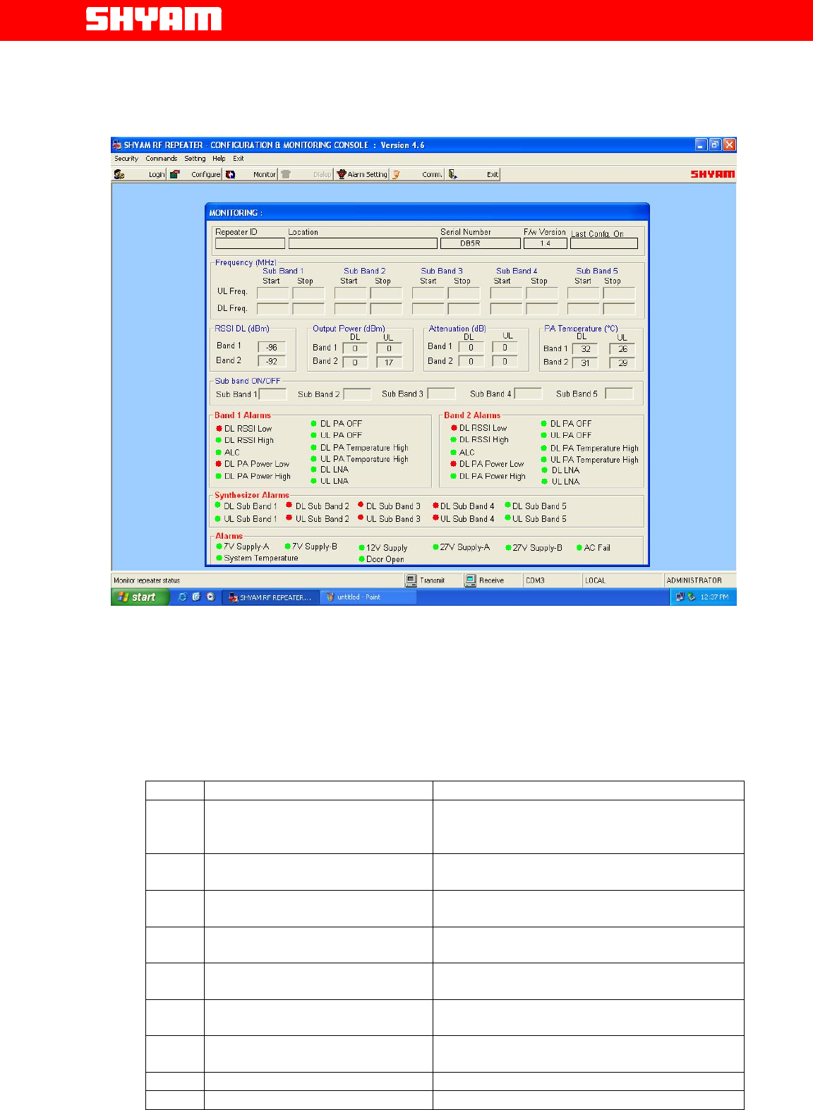
Figure 5: Monitoring & Alarm window
III) Monitoring (Figure 5)
In this window, the status of the system is monitored for the following
parameters/conditions:
S.NO. Parameters/Conditions Remarks
1. Frequency Bandwidth for
sub bands
It displays the bandwidth in DL & UL of
each sub band equipped.
2. RSSI (DL) Band 1
Real time value of DL signal level for Band
1 is indicated.
3. RSSI (DL) Band 2
Real time value of DL signal level for Band
2 is indicated.
4. Attenuation Band 1 (DL)
Indicates attenuation inserted in the
system for the band in DL.
5. Attenuation Band 2 (DL)
Indicates attenuation inserted in the
system for the band in DL.
6. Attenuation Band 1 (UL)
Indicates attenuation inserted in the
system for the band in UL.
7. Attenuation Band 2 (UL)
Indicates attenuation inserted in the
system for the band in UL.
8. Output Power Band 1(DL) Real time PA output power in dBm.
9. Output Power Band 2(DL) Real time PA output power in dBm.
. Page
All Rights Reserved Shyam Telecom Limited 16/35

Next Generation
Signal Enhancement
10. Output Power Band 1(UL) Real time PA output power in dBm.
11. Output Power Band 2(UL) Real time PA output power in dBm.
12. Sub band ON/OFF Displays the information about the sub
band equipped.
13. PA (DL) temperature for
band 1. Indicates the temperature of PA.
14. PA (DL) temperature for
band 2. Indicates the temperature of PA.
15. PA (UL) temperature for
band 1. Indicates the temperature of PA.
16. PA (UL) temperature for
band 2. Indicates the temperature of PA.
IV) Alarms (Figure 5)
Details of alarms displayed are detailed below:
S.NO. Alarm Indication Remarks
1. DL RSSI Low (Band 1 &
Band 2) When the low RSSI is detected in any of
the two or both bands, limits as set by the
user.
2. DL RSSI High (Band 1 &
Band 2) When RSSI in DL path exceeds the upper
limit in any of the two or both bands, as set
by the user.
3. DL PA Power High (Band 1 &
Band 2) When PA Power in DL path exceeds the
upper limit in any of the two or both
bands, set by user.
4. DL PA Power Low (Band 1 &
Band 2) When PA Power in DL path exceeds the
lower limit in any of the two or both
bands, set by user.
5. DL Auto PA OFF (Band 1 &
Band 2) When PA Auto OFF is detected in any of
the two or both bands in DL path.
6. DL Manual PA OFF (Band 1
& Band 2) When PA Manual OFF is detected in any
of the two or both bands in DL path.
5. DL PA Temperature High When PA Temperature in DL path
exceeds the upper limit in any of the two
or both bands set by user.
6. UL PA Temperature High When PA Temperature in UL path
exceeds the upper limit in any of the two
or both bands set by user.
7. Synthesizer failure (For
equipped sub bands in DL &
UL)
When the synthesizer in any of the
equipped sub bands fails, relevant alarm
is displayed.
8. LNA failure for Band 1 & 2 in
DL When LNA failure is detected in any of the
bands in DL.
9. LNA failure for Band 1 & 2 in
UL When LNA failure is detected in any of the
bands in UL.
10. ALC band 1` It indicates that ALC limit is exceeded.
11. ALC band 2 It indicates that ALC limit is exceeded.
12. AC fail Failure of AC mains to the system is
indicated by this alarm.
13. 7 V DC (A & B) failure Indicates the failure of 7 V DC supply.
14. 12 V DC failure Indicates the failure of 12 V DC supply.
15. 27 V DC (A & B) failure Indicates the failure of 27 V DC supply.
16. System Temperature Indicates the temperature of the system.
17. Door Open Indicates that the door has been opened.
. Page
All Rights Reserved Shyam Telecom Limited 17/35

Next Generation
Signal Enhancement
Monitoring interval is 3 seconds i.e. after every 3 seconds data on the
monitoring window is refreshed.
A red indication is for Alarm present.
A green indication is for No alarm.
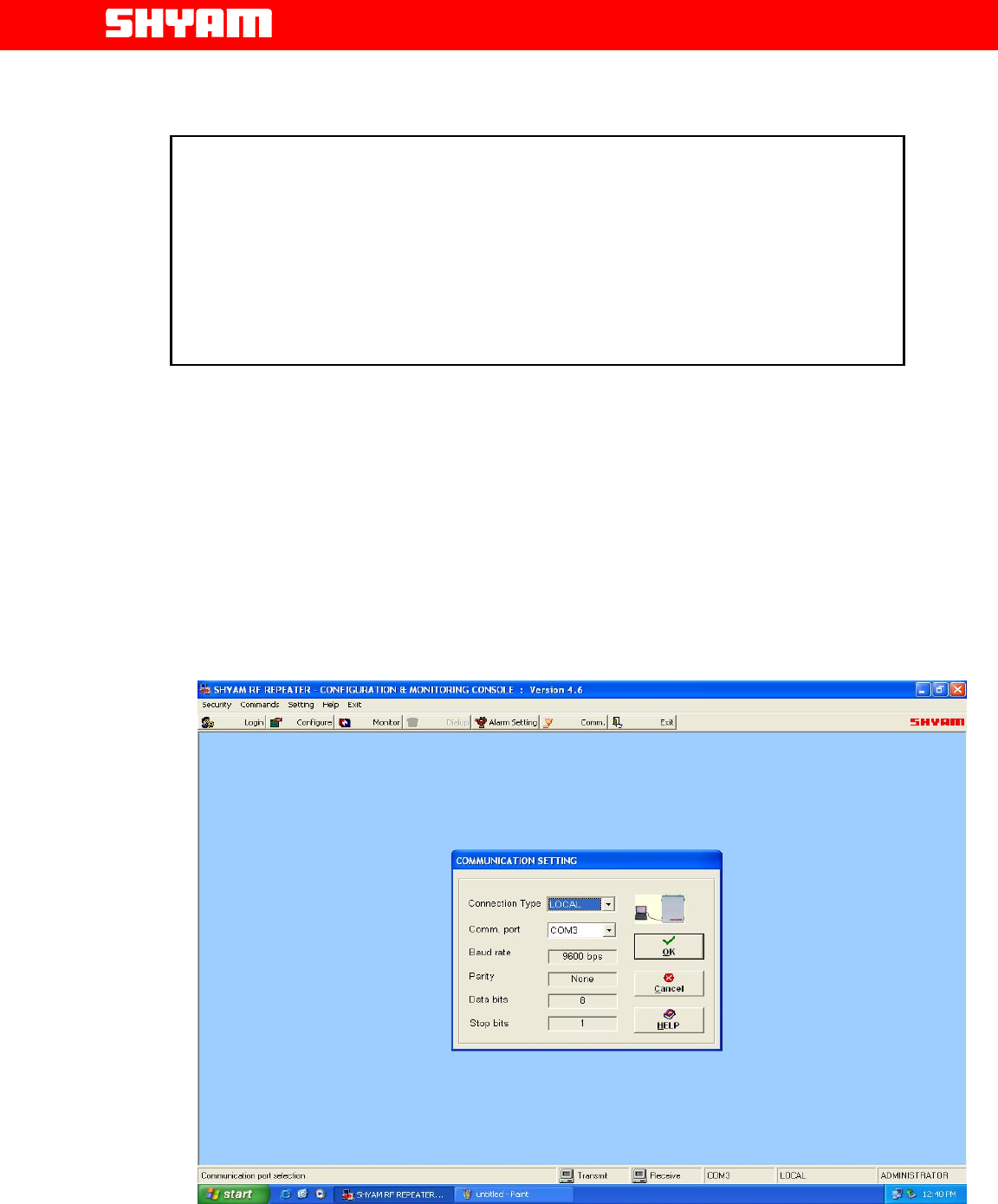
V) Communication Window (Figure 6)
In COMMUNICATION window, user can select serial communication port
of the computer and type of connection between repeater and computer.
There are two types of connections viz. Local and Remote
Local Connection: In this type of connection, User computer COM Port
and repeater’s USB Port are connected directly using cable. Sequence is
given below:
• Click the “COMM.” on the command bar to display the
COMMUNICATION window.
• Select the Connection Type as “LOCAL”
• Select the computer’s Comm. Port where the repeater is
connected.
• Click “OK”.
Remote Connection: This connection is established through Wireless
Modem.
In this type of connection, User communicates from/to remote location
with the repeater using wireless Modem / Cell phone.
To connect:
• Click the “COMM.” on the command bar to display the
COMMUNICATION window.
• Select the Connection Type as “REMOTE”.
• Select the computer’s Comm. Port where the wireless Modem
is connected.
• Click “OK”.
• Now click the DIALUP on the command bar to display the
DIALUP window.
• Enter / Select the repeater phone number.
• Click the “DIAL” and wait (maximum 60 seconds) for
connection.
A message “CONNECTED” will appear on the screen after the GSM
Connection is established.
Click the “DISCONNECT” on the DIALUP window to
disconnect remote communication with the repeater.
Wireless Modem (Optional) is equipped inside the housing of the
repeater and it can be easily located through a sticker provided on the
same. It has a groove with SIM cardholder in which the SIM card can be
inserted for remote communication.
. Page
All Rights Reserved Shyam Telecom Limited 18/35
Next Generation
Signal Enhancement
. Page
CAUTION
When the communication between repeater & PC/Laptop is in progress
through USB:
1. Do not remove cable from the USB port.
2. Do not switch off the repeater.
In case the communication is not required any more, click at EXIT before
removing cable from USB port to avoid hanging of the PC/Laptop. In case
the PC/Laptop goes in to hanging mode, it has to be restarted afte
r
closin
g
/switchin
g
OFF & ON the re
p
eater.
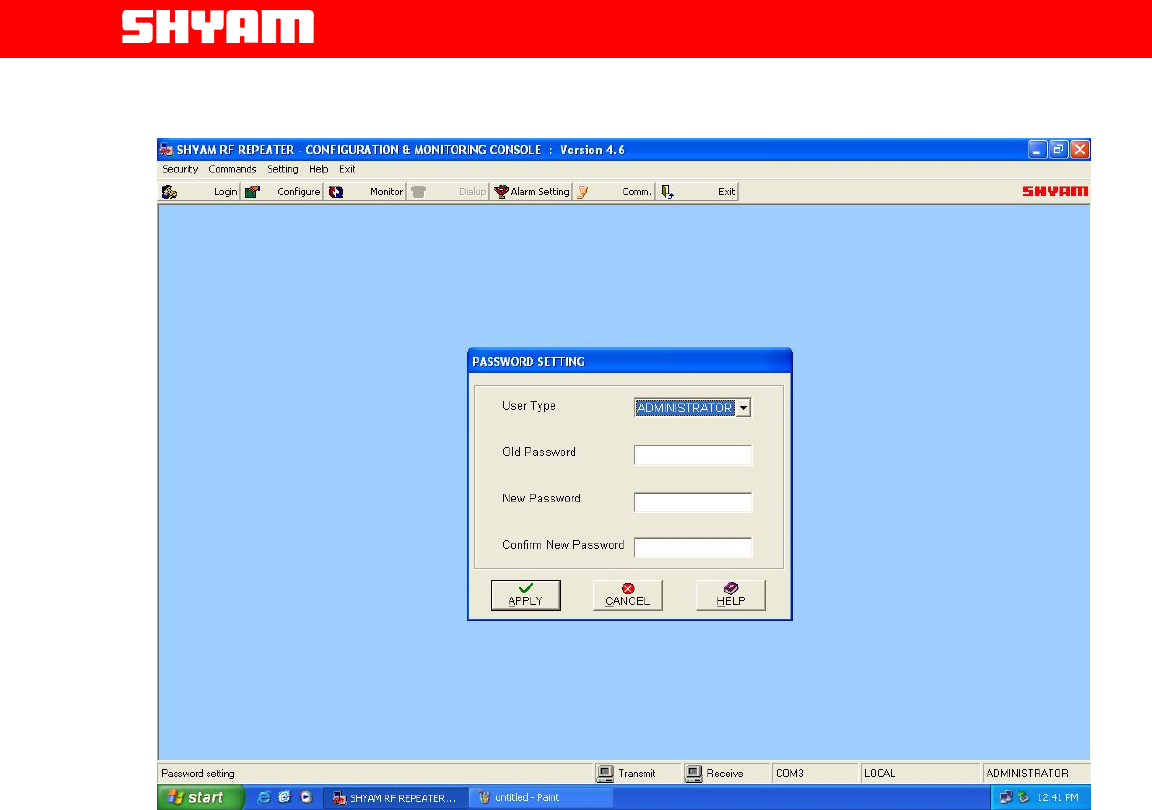
VI) Security Settings (Figure 7)
The system has two levels of permitting Log in to the repeater to avoid
unauthorized operation. The levels are: ADMINISTRATOR &
SUPERVISOR.
Each level has a specific password. The password for each level can be
changed at intervals. ADMINISTRATOR has rights to perform all
functions Viz. Configuration, Monitoring etc. Whereas the SUPERVISOR
is allowed to perform limited functions like monitoring of alarms,
establishing communication etc.
Figure 6: Communication Window
All Rights Reserved Shyam Telecom Limited 19/35
Next Generation
Signal Enhancement
Figure 7: Password Settings
6.3. Modules In DB5R-Description
The signals intercepted through the Donor antenna in the DL pass through
different modules/units for further signal processing; the detail explanation is
about different modules/units is given below:
a. DONOR Antenna
Donor antenna of appropriate bandwidth & gain interfaces the BTS on one
side and repeater system on other side through RF cable. It is used to
intercept signals from the base station and switch electromagnetic waves
into RF signals in the DL and vice versa in the UL.
. Page
All Rights Reserved Shyam Telecom Limited 20/35