Shyam Telecom DB5R33-8501900 Dual Band Repeater Cellular-850 + PCS-1900 User Manual User s manual for
Shyam Telecom Inc. Dual Band Repeater Cellular-850 + PCS-1900 User s manual for
Contents
- 1. Users Manual 1
- 2. Users Manual 2
- 3. Users Manual
Users Manual 2
Next Generation
Signal Enhancement
Figure 8: Donor Antenna
The Donor antenna with 16 dB gain transfers the intercepted signals
to the repeater and transmits uplink signals amplified by the repeater.
b. Diplexer
The signals received in the DL, through the antenna are split for individual
band processing. The dual band outputs are fed to two different
duplexers. One Diplexer is also provided before the server antenna in
order to distribute combined signals to mobile users.
In the UL, signals received from server antenna are split and fed to two
duplexers for processing. The amplified signals from both the duplexers
are combined for further transmission through Donor antenna to BTS.
c. Duplexer
The main function of duplexer is to isolate the uplink frequency from the
downlink frequency, i.e. isolate transmit path from receive path. Four
duplexer units are provided in the repeater, two in the Donor antenna side
and two in the server antenna side. Each duplexer transfers/receives
signals from respective diplexer for further connectivity to low noise
amplifier. The bandwidth of the duplex filter depends on the operator’s
frequency band (25MHz, 15MHz, 10MHz, 9MHz, or full Band etc.).
d. Low Noise Amplifier (LNA)
This module is provided after duplexer before the converter. The LNA
provides compensation for the losses suffered by the stream of weak
signals as it passes through splitter/combiner & duplexer (passive
devices). Four LNAs are provided, two each for individual bands in the UL
& DL directions.
. Page
All Rights Reserved Shyam Telecom Limited 21/35

Next Generation
Signal Enhancement
e. Converter Module
The basic block of converter module comprises of L.O., frequency mixer,
filter and intermediate amplifier. The low noise amplified signals are
converted to IF in frequency mixer with frequency fed from LO. The
signals are passed through sharply tuned filters. Number of converters
equipped shall depend on the number of sub bands configured in the
system. Two converters (one for DL & one for UL) for each sub band are
provided.
f. Power Amplifier
It is the core module of repeater. It includes driver stage and final stage. It
is installed directly on the heat sink of the repeater. Driver stage and final
stage of power amplifier are in the same unit. Four power amplifiers with
specific frequency bandwidths & gain are provided, two each for individual
bands in the UL & DL directions.
g. Supervisory
The man-machine communication between the cellular operator and the
repeater is established through this module. One of the two options as
given below can be used for achieving this objective:
• USB interface
• Wireless modem (Optional)
Remote controlling function of repeater can be achieved by equipping
Wireless modem. This arrangement also enables status of repeaters at
different locations to be monitored.
h. POWER SUPPLY
The power supply unit incorporated in the repeater is of high efficiency
and reliability. Different DC voltages required for the operation of
electronic circuitries are derived in this unit. The standard input voltage is
100 to 240 V AC, 47 Hz to 63 Hz. When the power supply varies in this
range and the frequency in 47 to 60Hz, its output DC derived voltages
remain constant within 1% of nominal value.
i. SERVER Antenna
Server antenna transmits signals from the repeater station to mobile users
and transport received uplink signals from the mobile users to the base
station. Based on the coverage area, a set of select panel antennas with
suitable gains & N type connecters is installed at pre-planned spots.
. Page
All Rights Reserved Shyam Telecom Limited 22/35

Next Generation
Signal Enhancement
Figure 9: Server Antenna
. Page
All Rights Reserved Shyam Telecom Limited 23/35
Next Generation
Signal Enhancement
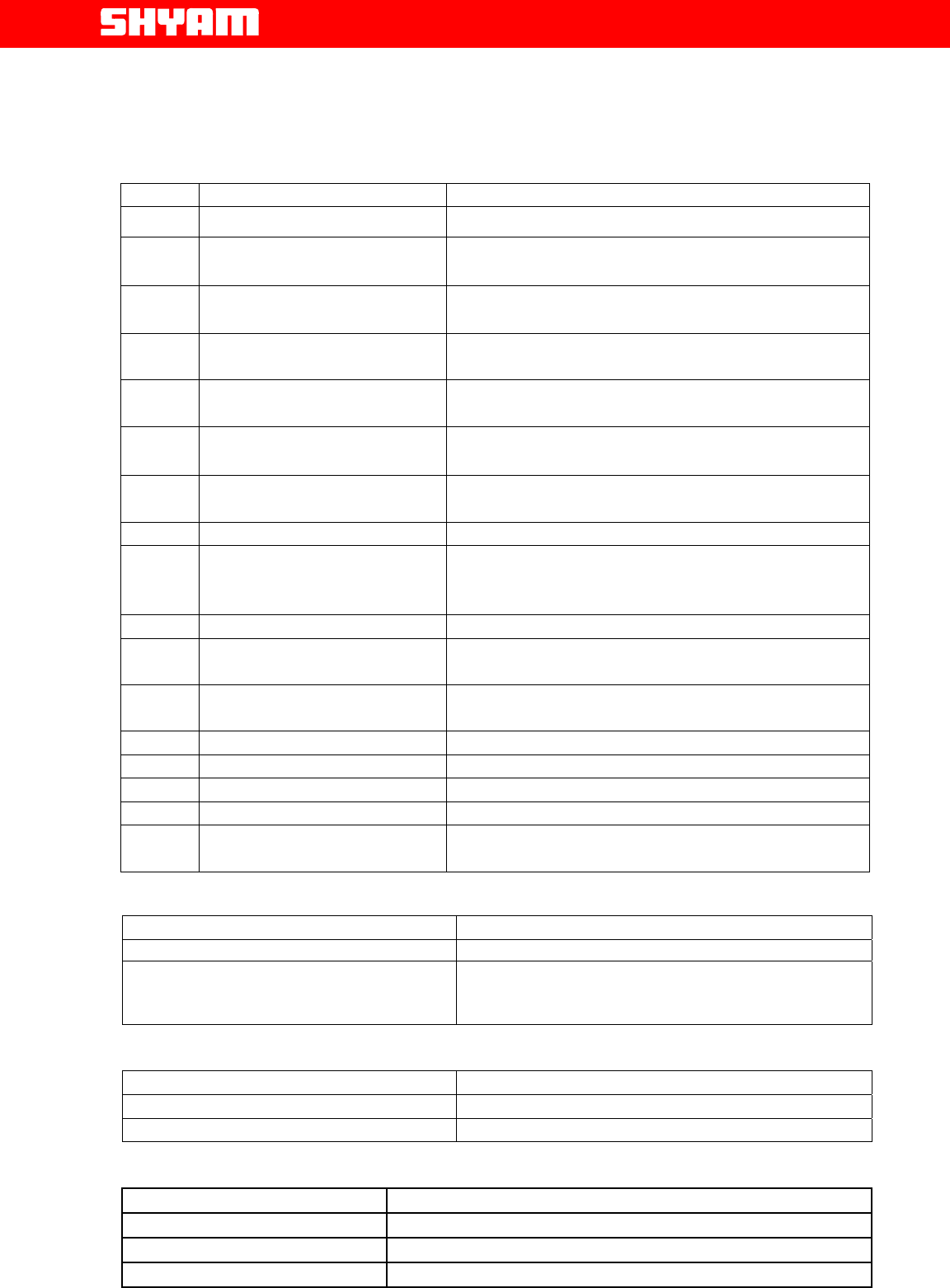
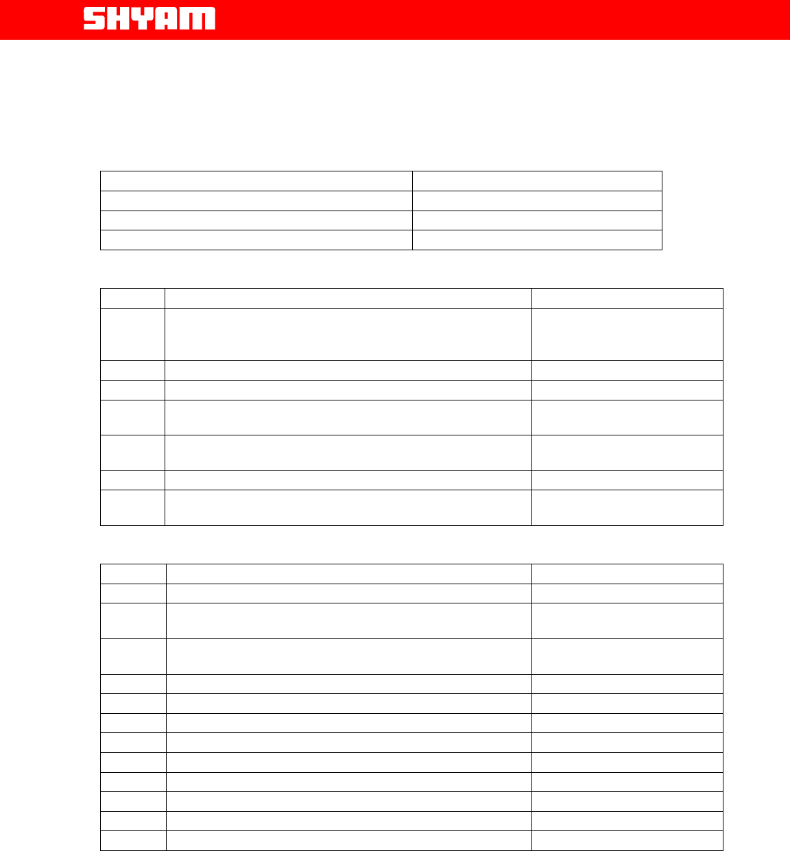
7. DB5R Repeater Specifications
7.1. Electrical Specifications-RF
S.NO. Parameter Specified limits/Remarks
1. Number of Bands Two,
2. Frequency band in DL
path. The bands are customized as per
requirement.
3. Frequency band in UL
path. The bands are customized as per
requirement.
4. Number of RF Sub
bands 5 maximum in 3+2 configuration. Set as per
requirement of the customer.
5. RF composite power
options DL +33 dBm
6. Spurious Emission ≤ 36dBm from 9 KHz to 1 GHz
≤ -30dBm from 1 GHz to 12.75 GHz
7. Automatic Power
Control 25 dB
8. Repeater Gain 85 dB (+-5dB)
9. Attenuation range for
gain adjustment in DL &
UL
31 dB in 1 dB step (Software control)
10. Gain flatness over band ±2 dB
11. Gain variation with
temperature ± 1.5 dB
12. Total delay in the signal
path/direction 5.5 microseconds.
13. Noise figure 5 dB Max.
14. Impedance 50 Ohms
15. Return loss 16 dB
16. Power supply 100 to 240 V AC, 47/63 Hz
17. RMS interface Wireless modem (optional), USB port for local
connection.
7.2. Electrical Specification Power Requirement
Parameters Specified/Limits
Input AC Voltage Range 100-240 V, 47/63 Hz
Power Consumption approx.
175 watts (Varies as per number of sub bands
equipped)
7.3. External Electrical Interface
Parameters Specification
RF port UL N-type (F)
RF port DL N-type (F)
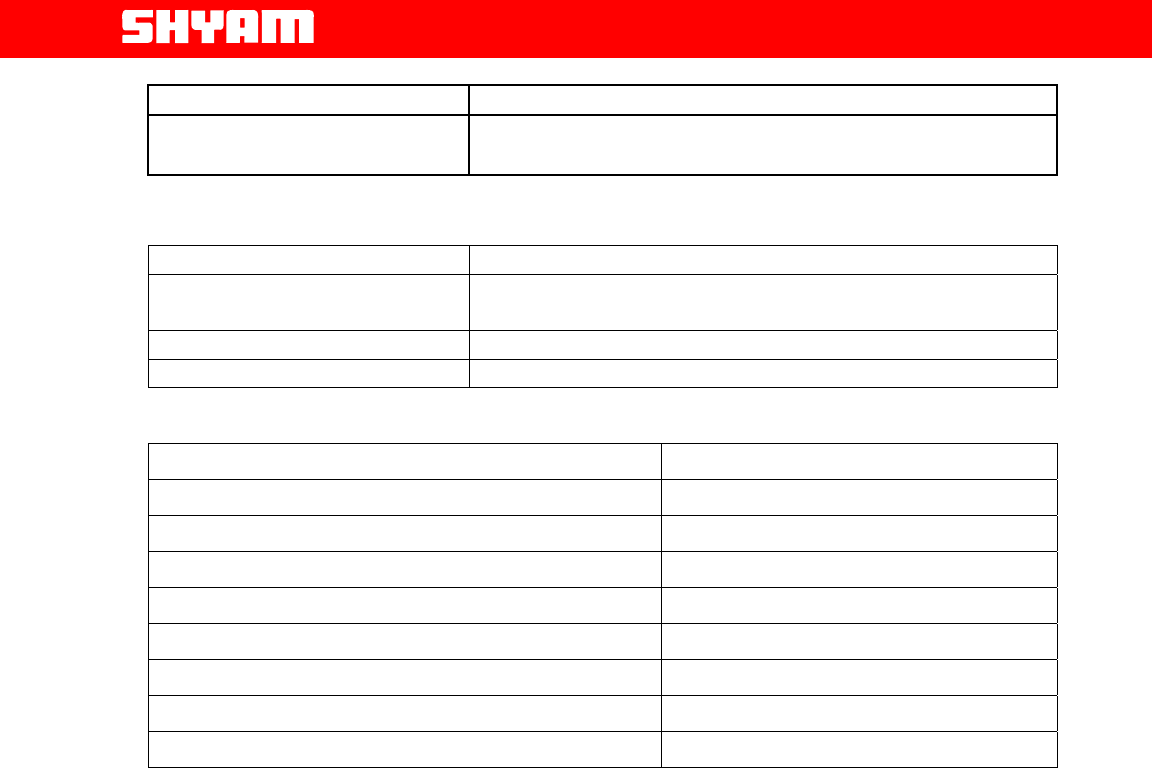
7.4. Mechanical Specification
Dimensions (w x h x d)
5
60x445x200 mm (22x17x8 inches)
Weight 30 Kg. (72 lbs.)
Housing Metal for Outdoor application
Grounding Connection Bolt
. Page
All Rights Reserved Shyam Telecom Limited 24/35
Next Generation
Signal Enhancement
Housing Color Grey
Cooling Convection
7.5. Environmental Specification
Conditions Specification
Operating Temperature -35oC to +550C (-310F to +1310F)
Storage Temperature -300C to +750C (-220F to +1670F)
Enclosure IP-65 (NEMA 5)
7.6 Contents of Delivery
ITEMS QUANTITY
Repeater DB5R unit 1
PC interface cable for USB port 1
Power cable 3 pin 1
Operation & Installation manual 1
CD containing the application software 1
Wireless Modem (Optional) 1
Repeater Door Key 1 set
Screws, Nuts & Bolts for mounting 1 set
. Page
All Rights Reserved Shyam Telecom Limited 25/35
Next Generation
Signal Enhancement
8. Installation
8.1. Preparation Sheet- Pre Installation
Before the installation commences, a preparation sheet to examine the various
requirements is to be compiled as per detail given below:
1. General
Application: Outdoor
Service Band 1: Frequency Band DL- Frequency Band UL-
Service Band 2: Frequency Band DL- Frequency Band UL-
Number Of Sub Bands: six
Sub Band 1: Frequency Band DL- UL-
Sub Band 2: Frequency Band DL- UL-
Sub Band 3: Frequency Band DL- UL-
Sub Band 4: Frequency Band DL- UL-
Sub Band 5: Frequency Band DL- UL-
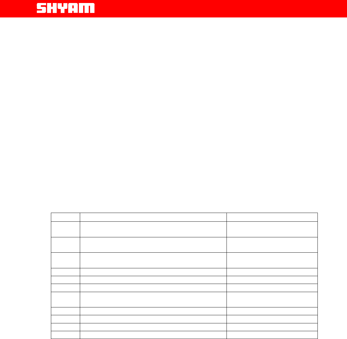
2. Technical requirements
S.NO. Requirement Remarks
1. Estimated received signal strength available at
site where donor antenna is to be installed
2. Estimated cable loss from donor antenna to the
repeater unit
3. Estimated DL RF power to the input to the
repeater
4. Desired RF Power in DL
5. Proposed gain settings in DL path
6. Attenuator to be inserted in DL path
7. Estimated cable loss from repeater unit to
server antenna port
8. ERP at server antenna
9. Desired RF Power in UL
10. Proposed gain settings in UL path
11. Attenuator to be inserted in UL path
3. Proposed site Address:---------------------------
4. User’s Address & other particulars:---------------------------------
Date: Prepared by:-------------
. Page
All Rights Reserved Shyam Telecom Limited 26/35

Next Generation
Signal Enhancement
8.2. Engineering Consideration
a. Site Selection
Site selection is one of the most critical decisions affecting the overall
performance of the system. A repeater must be located where it can
receive the maximum signal from the donor site in order to maximize the
repeater’s output and performance, a signal strength greater than or equal
to -75dBm is desired.
Examples of repeater (and accompanying antenna) locations include (but
are not limited to): the roof of a building adjacent to the affected area, with
the antennas mounted at the highest point in the building; the top of the hill
that is obstructing the donor site’s coverage, with the antennas mounted on
poles at ground level or as the situation permits.
Distance from both the donor site as well as from the new area to be
covered must be taken into consideration. The repeater unit should be
located close to the donor site to receive maximum signal strength and at
the same time is located in the vicinity of area where coverage is desired.
In addition, the donor antenna associated should have line of sight with
BTS site to reduce the effects of fading.
Another important issue when choosing a repeater location is the
availability of commercial power. Sites where repeater unit is installed
should be easily accessible for the maintenance team.
b. Antenna Selection and Placement
Proper selection of the repeater’s donor and server antennas is crucial in
designing the repeater system. Good antenna characteristics help to
provide proper isolation between the server (coverage) and donor
antennas, which helps to prevent feedback. An isolation of at least 15dB
more than the gain setting of the repeater is required. If the isolation is less
than the repeater gain, oscillation will occur.
Specific ways to achieve proper isolation include: using high gain,
directional antennas with good Front to Back ratios (25dB or better);
physical separation of the repeater’s donor and server antennas; and
external shielding between antennas. A high gain antenna will help
minimize overall path loss to achieve the desired output power. Donor
antenna gains are typically 16 dB, while server antennas with proper
gains are installed.
• The antennas should have proper frequency band of operation.
• Adequate separation is to be ensured from the power lines to
avoid damage to the equipment and humans.
. Page
• Antenna with proper characteristics to maintain adequate isolation
to avoid oscillations. Normally, isolation should be 15 dB more
than the gain set for the repeater. It should have good front to
back ratio.
All Rights Reserved Shyam Telecom Limited 27/35
Next Generation
Signal Enhancement
• The beam width for the DONOR antenna should be as small as
possible.
• The beam width for SERVER antenna is 60 degree to 120 degree.
• There should be adequate vertical & horizontal separation
between the DONOR & SERVER antennas to avoid interference
and noise. Separation can be determined by the mathematical
formulas:
Vertical Separation:
Isolation (dB) = 28 + 40 log (D/ʎ in m)
Horizontal Separation:
Isolation (dB) = 22 + 20 log (D/ʎ in m) – (Gain of donor antenna
+ gain of server antenna)
D-Distance between donor & server antennas in m
ʎ- wavelength in m
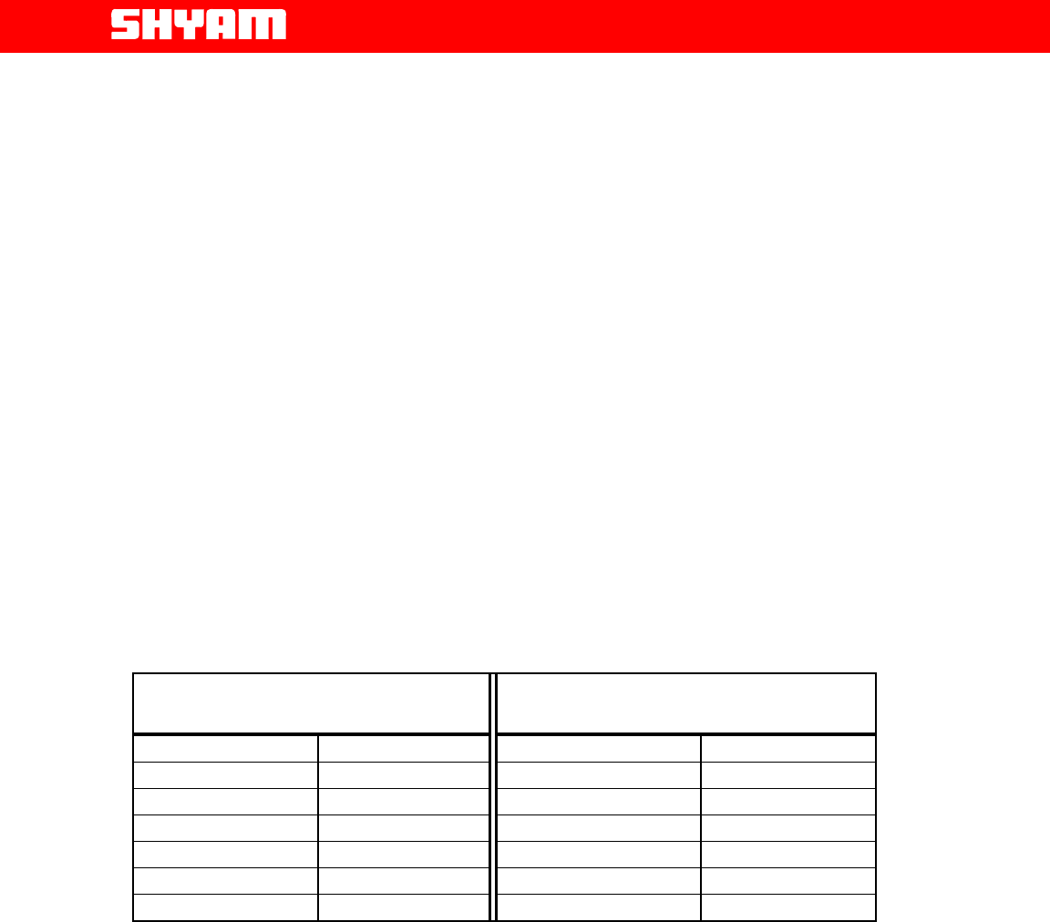
The following table is an approximate guide to antenna
separation.
The use of highly directional antennas with good front to back
ratios can help to reduce isolation requirements.
VERTICAL ANTENNA
SEPARATION HORIZONTAL ANTENNA
SEPARATION
Separation (m.) Isolation (dB) Separation (m.) Isolation (dB)
5 75.0 5 45.5
10 87.1 10 51.7
20 99.1 50 65.5
30 106.2 100 71.5
40 111.2 150 75.1
50 115.0 250 77.6
Vertical and Horizontal Antenna Separation @ 900 MHz
The antenna separation table demonstrates that vertical separation yields
better results than horizontal separation. However, when desired isolation
cannot be met due to insufficient separation, external shielding can help; for
example, mounting the antennas on either side of a rooftop penthouse or
using some type of grounded metal screen or wire mesh (so called chicken
wire) between antennas.
The following example illustrates the various signal levels and antenna gains
needed to form a properly functioning repeater system.
Received Signal Level -72 dBm
Donor Antenna gain 16 dBi
Cable loss (100 ft. of 7/8 inch) 2 dB
Input to Repeater -62 dBm
Gain of Repeater set 85 dB
Output of Repeater +33 dBm
. Page
All Rights Reserved Shyam Telecom Limited 28/35

Next Generation
Signal Enhancement
Cable loss (100 ft. of 7/8 inch) 2 dB
Server Antenna Gain 9 dBi
Repeater ERP +41 dBm
c) Overlapping Coverage
Ideally, the repeater system will be engineered with minimal overlapping
coverage between the donor base station and the repeater. However, the
mobile users will occasionally receive signals from both the donor and the
repeater at similar levels. This situation is comparable to a mobile receiving
multiple signals at varying times due to multi-path propagation.
This repeater contributes a maximum signal delay of 5.5 microseconds in
one direction.
d) Call Processing
The mobile communication system perceives calls handled by the repeater
as actually being handled by the donor site (BTS); the repeater is just an
extension of the base station’s coverage. Therefore, the donor handles call
initiation, power control messages, hand-over requests, etc., for mobiles in
the repeater area. When the base station assigns a channel to the mobile,
that channel is sent through the repeater and then reradiated under the
same frequency. Since the repeater is technically part of the base station,
no hand-over takes place when a mobile moves from the repeater’s
coverage area to that of the base station. When the mobile moves from the
repeater’s area to a neighboring site, the base station handles the hand-off
in the same way as for a mobile in the base station area.
8.3. Installation Tools
You will need the following basic tools for installation:
a. Standard wrenches/screwdrivers/cable stripper/cable cutter/pliers set
for installing the DB5R Unit and antennas. (Refer to the
manufacturer’s recommendations for installing the antennas).
b. RF coaxial cable connection tools for installing connectors.
c. Multi-meter.
d. Mobile handset loaded (e.g. Nokia) with Net engineering software to
be used for signal level measurement.
e. Magnetic compass for measuring the azimuth of the BTS and
repeater site.
8.4. Installation Procedure
The DB5R repeater has been designed for outdoor applications. The repeater
unit shall be mounted vertically to a mast, which means the RF connectors
will be at the bottom side.
In case of wall mounting, minimum physical separation between the repeater
housing & the wall should be 50 mm.
Furthermore, the repeater shall be mounted in a way so that there is free
access to the individual units, while the door of the repeater is open.
. Page
All Rights Reserved Shyam Telecom Limited 29/35

Next Generation
Signal Enhancement
The repeater is mounted at the pre-selected site firmly placed with clamps
and other mechanical accessories. Connections as detailed are carried out:
• RF cable routed from DONOR antenna is connected at the BTS port as
indicated.
• RF cable routed to SERVER antenna is connected at TX/RX port for
signal distribution.
• For energizing the system, the cable from AC mains is connected at
AC mains port, range 100-240 V.
• USB port is provided for carrying out configuration and monitoring.
Important: Grounding of the unit has to be ensured before extending the
power to the repeater system.
Following points need considerations for laying of RF cable:
1. RF coaxial cable installation must comply with local or National Electrical
Codes. The cable shall have nominal 50-Ohm impedance. Routing of the
RF coaxial cables is to be as per the site installation plan.
2. Fix the supplied connectors to the RF coaxial cable and verify the
following:
• The center conductor to outer shield of RF coaxial cable indicates an
“Open Circuit” condition.
• Check for any short circuit between center conductor and outer
shield.
• Place short between the center conductor and outer shield using a
piece of wire temporarily and check the other end of conductor for
any break in the RF cable.
8.5. Repeater Gain Settings
The repeater gain setting is one of the vital parameters since it also decides
the area to be provided with RF coverage. The noise contribution has to be
minimum while setting the gain hence it should be set with utmost care. The
variation in gain up to 31 dB in steps 1 dB is possible to be achieved with the
help of software control attenuator, provided in the system. The gain setting
for Uplink and Downlink path is independent of each other.
For example, if repeater has a maximum gain of 85 dB and the required
repeater gain is 60 dB, the attenuation of 30 dB is required to be incorporated
by inserting attenuator of this value.
Note: Repeater gain should be at least 15 dB less than the antenna isolation.
Signals intercepted by DONOR antenna from BTS and transmitted to the
repeater are termed as Downlink/Forward signals and the signals originated
by mobile users and intercepted by SERVER antenna for application to
repeater are termed as Uplink/Reverse signals.
a. Forward Gain Setting
The process of setting the forward gain is very simple. Forward signal
level strength can be measured using NET engineering software in any
NOKIA handset e.g. NOKIA 6210 or any other engineering mobile
handset.
. Page
All Rights Reserved Shyam Telecom Limited 30/35

Next Generation
Signal Enhancement
Alternatively, RF output power of repeater can be measured using the
visual indication shown on the display panel of the repeater.
Once the RF output power has been determined, the attenuation will have
to be modified to reach the desired output signal level.
The gain of repeater can be set using any of the following methods:
a. Local manual mode (using built in key pad and display)
b. Local USB serial interface mode (GUI based)
c. Through (optional) wireless modem.
b. Reverse Gain Setting
For reverse gain setting, a 31 dB variable attenuator is provided; the
required value can be inserted for the desired gain. The gain is set to
such a value so as to cause minimum interference at the base station but
high enough to ensure a strong signal.
Generally, reverse gain is set 5db less than the forward signal.
8.6. Commissioning
Note:-Repeater should not be connected to Power without termination
of the antenna connection. The termination can be performed either by
the antenna connection as well as a dummy load or the 50
Ω
terminated connection of a measuring instrument (Power Meter,
Spectrum analyzer with appropriate PAD)
After setting the gain, verify the parameters:
1. DL RF power radiated in the set frequency band.
2. Received RF power in the DL.
3. UL RF power radiated in the set frequency band.
4. Received RF power in the UL.
5. Record the value of attenuation introduced for setting the gain.
8.7. Dos & Don’t Dos
The site should be accessible for the maintenance team.
1. Arrangement is to be made to avoid unauthorized access to the repeater.
2. Proper grounding of the repeater is required to be done to avoid damage
to the system.
3. For outdoor applications, the housing must be waterproof.
4. Stable power supply for repeater unit should be ensured.
5. The route of Cables to/from antennas should be short to limit the cable
losses and should be free from sharp bends & kinks.
6. Local standard of cabling should be followed.
7. The donor antenna should have proper line of sight with the BTS from
where the signals are to be intercepted for maximum signal strength and
to reduce the effect of fading.
8. There should be adequate separation between the cables (antenna
system) and the power lines to avoid damage to the equipment & injury
to humans.
10. The selection of BTS should be made taking other BTSs in the same
vicinity in to consideration to avoid interference.
. Page
All Rights Reserved Shyam Telecom Limited 31/35

Next Generation
Signal Enhancement
11. Gain of the repeater should be set after taking antenna isolation in to
consideration.
12. The estimation of coverage area should be confirmed.
13. The system should be made over for normal traffic after actual
measurement of:
a) RF power in the DL
b) RF power in the UL
c) Antenna Isolation
d) Gain settings in DL & UL
14. Feedback regarding performance of the system must be obtained from
the user.
. Page
All Rights Reserved Shyam Telecom Limited 32/35
Next Generation
Signal Enhancement
8.7.Checklist – Post Installation
After the installation of the system is accomplished, points as indicated in the
checklist are verified.
Service Bands Particulars:
Frequency Band for Band 1 DL
Frequency Band for Band 1 UL
Frequency Band for Band 2 DL
Frequency Band for Band 2 UL
A. Repeater Installation
S.NO. Point(s) To be Verified Remarks
1. Ensure isolation between server and donor
antennas, it has to be 15 dB + Gain set of the
repeater.
2. Actual isolation measured
3. Ensure proper grounding of the unit
4. Cable from donor antenna connected to donor
antenna port
5. Cable from server antenna connected to the
relevant port in the unit
6. Mains cable connected to the repeater unit
7. Cable protection ensured and outdoor connections
are waterproof
B. Repeater Set Up
S.NO. Point(s) To be Verified Remarks
1. Number of sub bands equipped
2. Number of Sub band(s) in Band 1 with frequency
bandwidth of each.
3. Number of Sub band(s) in Band 2 with frequency
bandwidth of each.
4. Repeater switched ON
5. Any error (alarms) observed
6. Gain set
7. Power level in DL
8. Attenuation in DL
9. Power level in UL
10. Attenuation in UL
11. Observation on CMC software & GUI
12. Repeater secured & locked
Any Other Remark/Comment:
Date Of Installation:------------------------ Repeater ID & Site Address:---------------
Name of the Installer:-----------------------------------------------------
. Page
All Rights Reserved Shyam Telecom Limited 33/35

Next Generation
Signal Enhancement
9. System Maintenance
9.1. General
The system normally operates without any operator intervention or
maintenance. If, in the unlikely event of a unit failure, the field replaceable
units (antenna unit, cables) should be checked for faults and the system
restored. The faulty unit can be removed and replaced with a spare while the
rest of the system is still operating. Soldering or local repair of the modules
should be avoided for better maintenance point of view. Faulty module/unit
should be replaced with genuine spares from Shyam Telecom Limited only.
However, the power supply of the failed repeater should be isolated from AC
mains and DC power before any module is replaced. In the event of a
system malfunction, the status of the antenna systems should be checked
as well as the continuity of the cabling before replacing any modules within
the repeater.
9.2. Preventative Maintenance
The DB5R repeater does not require any preventative maintenance.
. Page
All Rights Reserved Shyam Telecom Limited 34/35
Next Generation
Signal Enhancement
For Technical Support, please contact at any of the following addresses:
For Americas
Shyam Telecom Inc.
6, KILMER ROAD, SUIT D,
EDISON, New Jersy-08817 (USA)
For Europe
Shyam Telecom GmbH.
Frohsinnstrasse 16, 63739 Aschaffenburg, Germany
Tel: + 49-6021-45901-0 Fax: + 49-6021-45901-29
For ASEAN & Others
Shyam Telecom Ltd.
246, Phase IV, UDYOG VIHAR,
GURGAON – 122015 (INDIA)
Tel: +91-124-4311600 FAX: +91-124-4018117
Email: contact@shyamtelecom.com
. Page
All Rights Reserved Shyam Telecom Limited 35/35