Shyam Telecom DB6MR20 Dual Band Indoor Repeater User Manual
Shyam Telecom Inc. Dual Band Indoor Repeater Users Manual
UserManual.wiki
>
Shyam Telecom
>
DB6MR20 User Manual
Users Manual
Navigation menu
Upload a User Manual
Namespaces
Wiki Guide
HTML
PDF
Info
Views
User Manual
Discussion / Help
Navigation
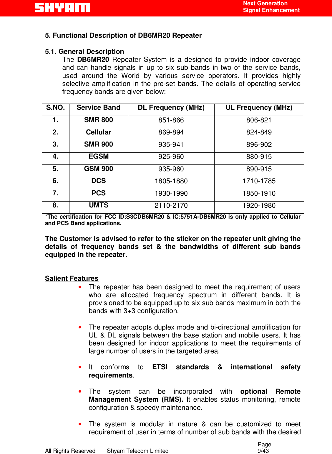
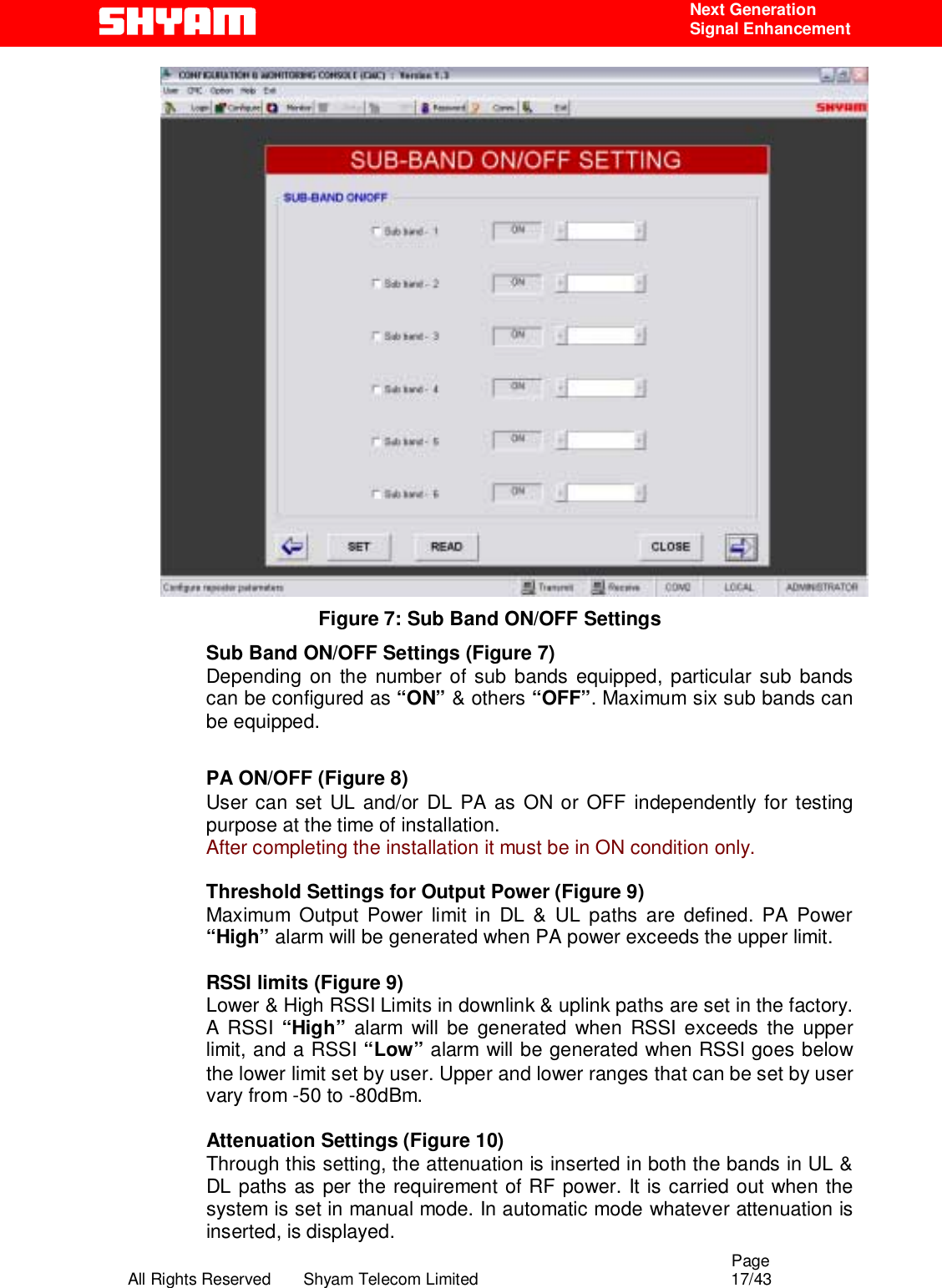
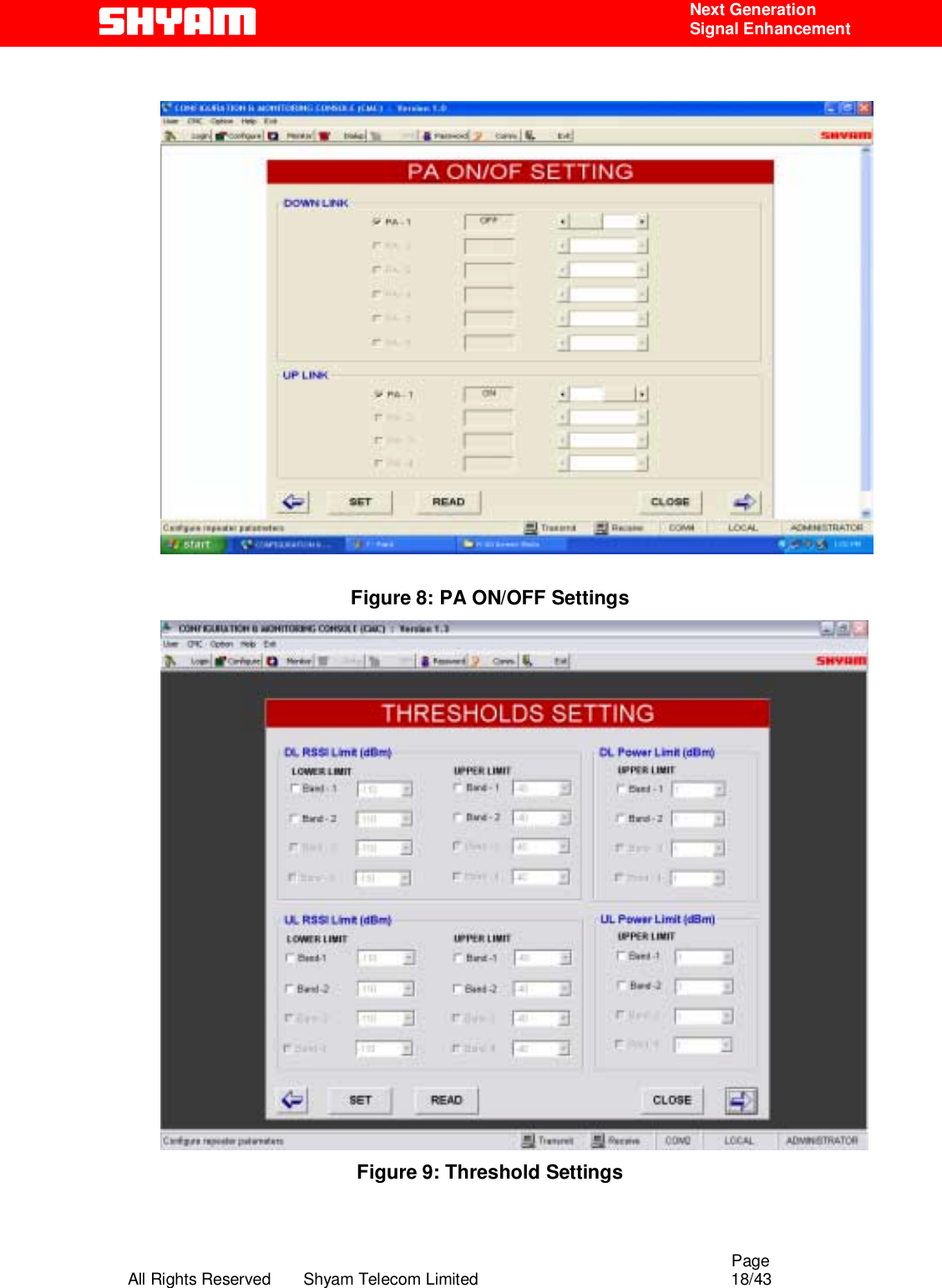
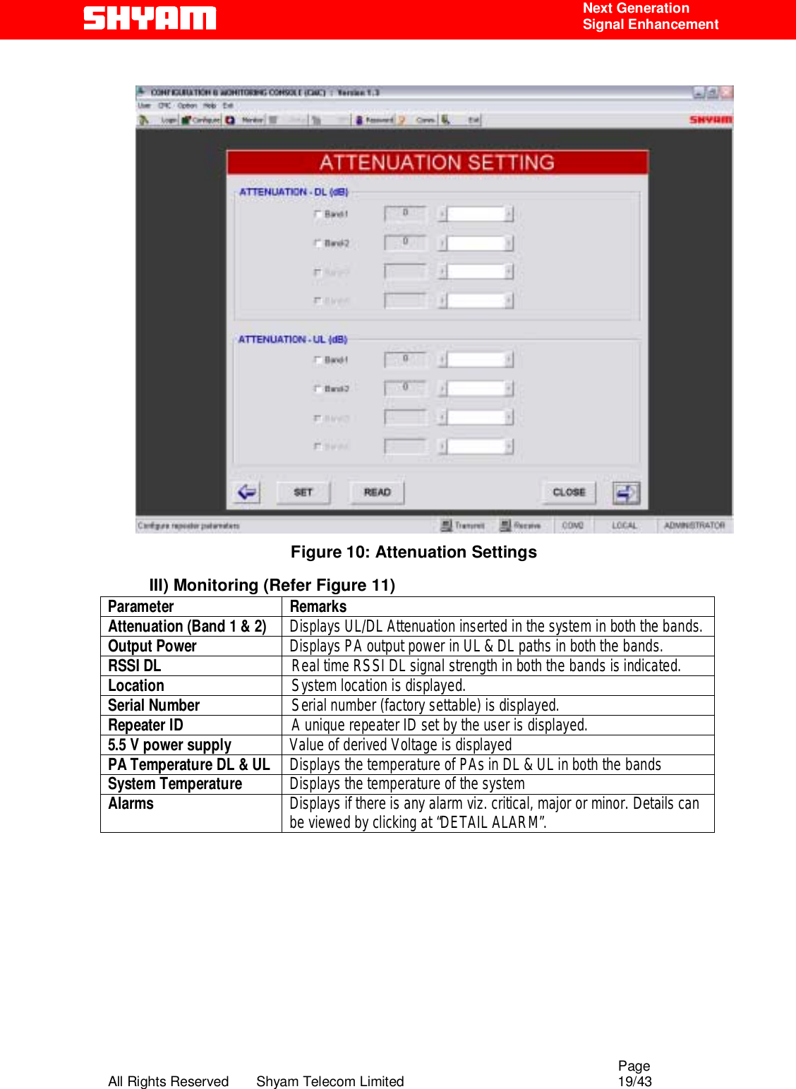
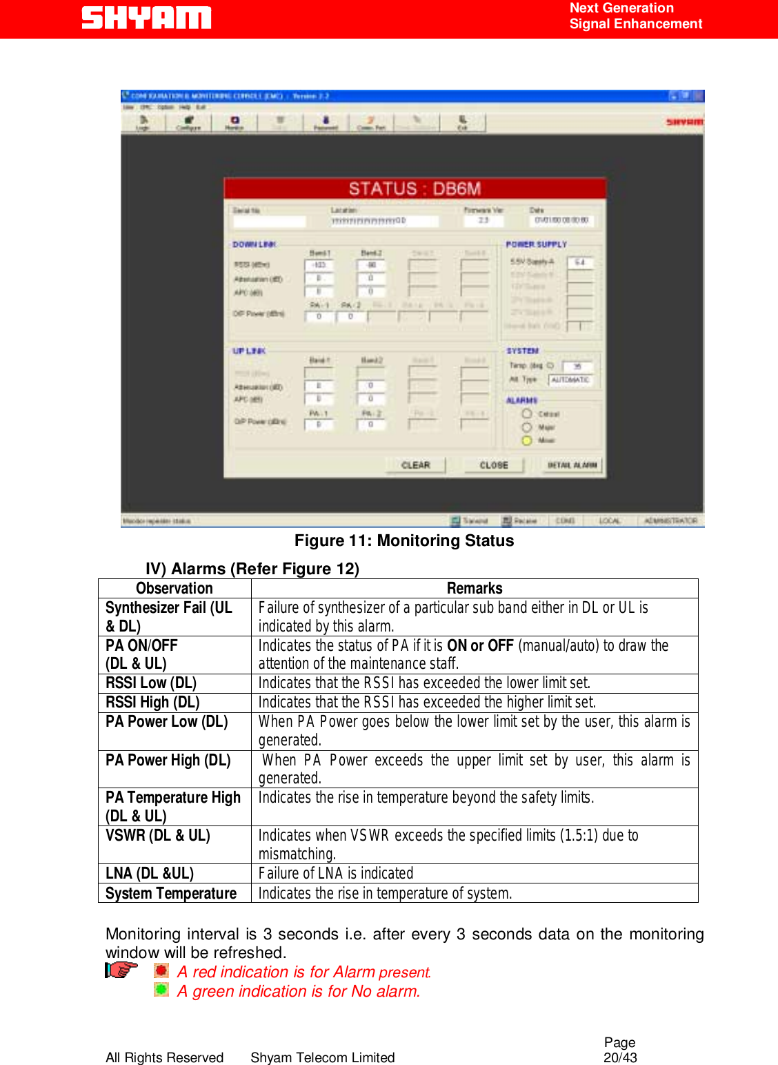
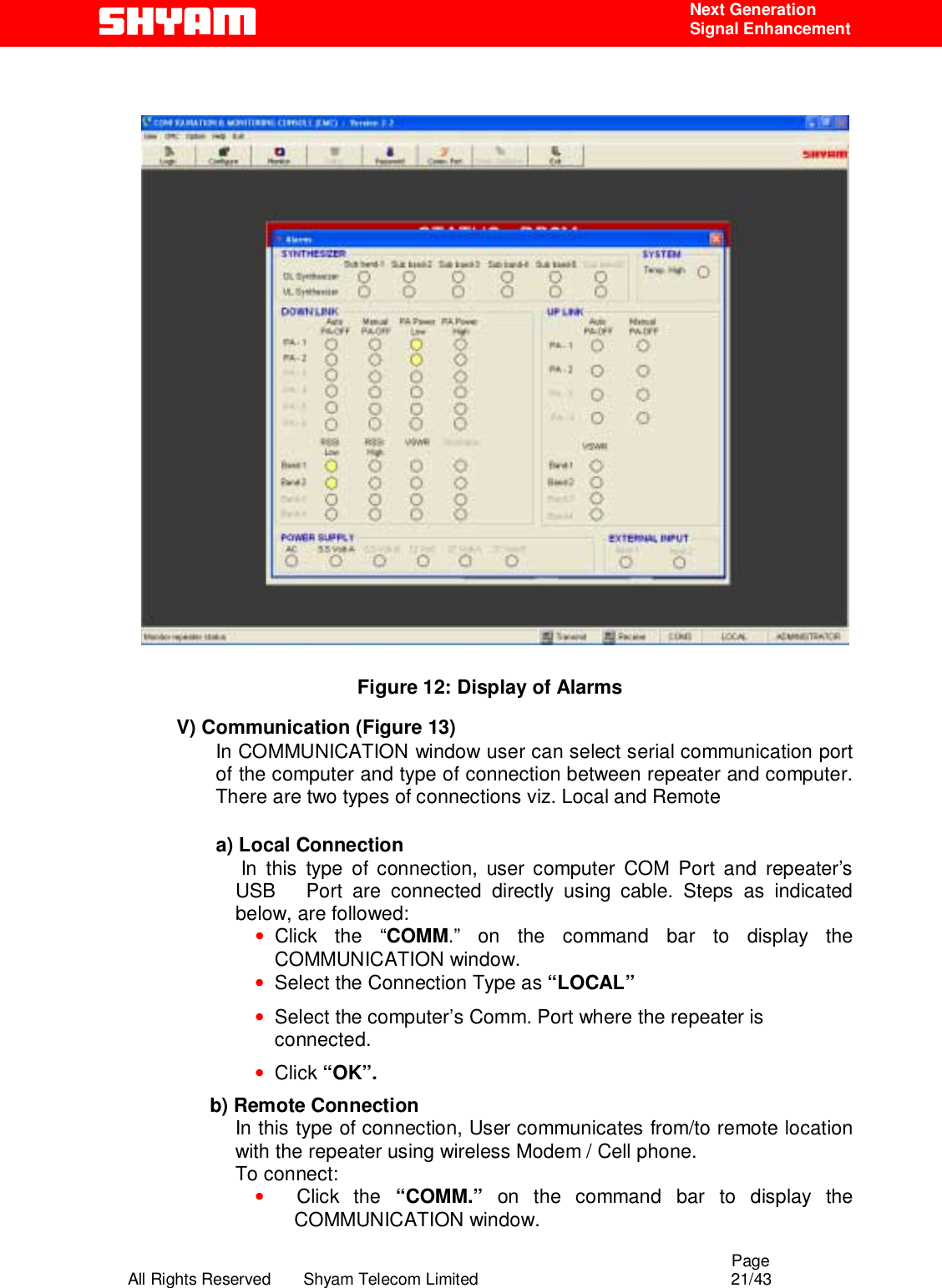
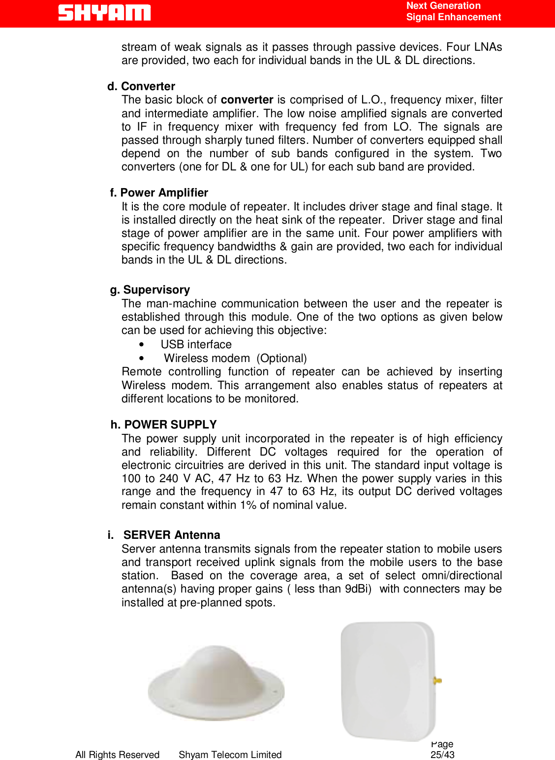
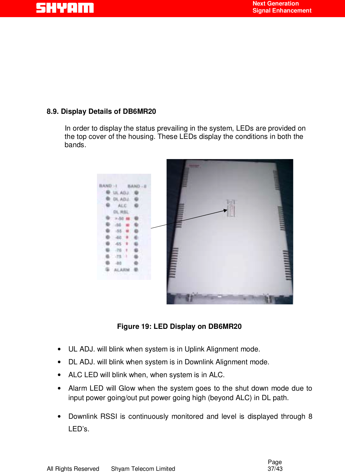
![Page All Rights Reserved Shyam Telecom Limited 8/43 Next Generation Signal Enhancement 4.4. References [1] ETS 300 086. Radio Equipment and Systems Land mobile service Technical characteristics and test conditions for radio equipment with an internal or external RF connector intended primarily for analogue speech. [2] ETS 300 609-4. Digital cellular telecommunications system (phase 2): Base Station Systems (BSS) equipment specification: Part 4: Repeaters. [3] ETS 300 342-3 Radio Equipment and Systems (RES): Electro-Magnetic Compatibility (EMC) for European Digital Cellular Telecommunications systems. Base Station Radio and ancillary equipment and Repeaters meeting phase 2 GSM requirements. 4.5. General Mobile Communications Systems are planned as cellular systems and each cell of the base station is required to provide RF coverage over a certain geographical area as per defined RF power levels. Due to the RF propagation properties, even using high radiated RF powers or complicated antenna systems, there are zones within the coverage area where the RF signal strength from base station remains inadequate for establishing the desired connectivity to mobile users. Repeaters traditionally are deployed in the Mobile Communication Network to fill in the “Dead Zones” caused by blocking of signals by geographic topologies such as mountains, valleys, dense foliage, high rising urban landscapes and other man-made structures. The distance from the base station also adversely affects the RF signal strength. The user views repeaters as a means to extend base station coverage so as to reduce the number of base stations and thereby accelerate network availability. Repeater systems are installed after meticulous planning between BTSs and the mobile users to provide RF coverage in the shadowed regions. Repeater systems are available for different applications and ultimate choice shall depend on some of the factors mentioned below: • Area to be provided with coverage. • Indoor/outdoor coverage. • Availability of BTSs in the vicinity. • Antenna isolation to be achieved.](https://usermanual.wiki/Shyam-Telecom/DB6MR20/User-Guide-1069659-Page-8.png)