Shyam Telecom DB6MR20 Dual Band Indoor Repeater User Manual
Shyam Telecom Inc. Dual Band Indoor Repeater Users Manual
Users Manual
Page
All Rights Reserved Shyam Telecom Limited 1/43
Next Generation
Signal Enhancement
RF / DBR Series
O
OP
PE
ER
RA
AT
TI
IO
ON
N
&
&
I
IN
NS
ST
TA
AL
LL
LA
AT
TI
IO
ON
N
M
MA
AN
NU
UA
AL
L
FCC ID:S3CDB6MR20 IC: 5751A-DB6MR20
5920 0060 200 December 2008
Proprietary Information
The information contained herein is proprietary to Shyam Telecom Limited.
Unauthorized access, copy and replication are prohibited. This document must not
be copied in whole or part by any means or it shall not be disclosed or divulged to
any third Party without the prior written consent of Shyam Telecom Limited.
D
DB
B6
6M
MR
R2
20
0 (
(Dual Band)
Six Sub-Band Repeaters for In-Door Applications

Page
All Rights Reserved Shyam Telecom Limited 2/43
Next Generation
Signal Enhancement
Contents
1. Document History.........................................................................................4
2. Disclaimer......................................................................................................5
3. Safety Instructions and Warnings...............................................................5
3.1. Personnel Safety .....................................................................................5
3.2. Equipment Safety ....................................................................................5
3.3. Electrostatic Sensitivity............................................................................6
4. Introduction...................................................................................................7
4.1. Purpose ...................................................................................................7
4.2. Scope ......................................................................................................7
4.3. Definitions................................................................................................7
4.4. References ..............................................................................................8
4.5. General....................................................................................................8
5. Functional Description of DB6MR20 Repeater........................................... 9
5.1. General Description.................................................................................9
5.2. Typical In-Building Coverage.................................................................11
6. To Get started-Basic Software Control of the System.............................14
6.1. General..................................................................................................14
6.2. Terminal Set-up .....................................................................................14
6.3. Block Diagram Description ....................................................................24
7. DB6MR20 Repeater Specifications............................................................26
7.1 Specification-RF .....................................................................................26
7.2. Electrical Specification Power Requirement ..........................................26
7.3. External Electrical Interface...................................................................27
7.4. Mechanical Specification .......................................................................27
7.5. Environmental Specification ..................................................................27
7.6. Contents of Delivery ..............................................................................27
8. Installation...................................................................................................28
8.1. Preparation Sheet-Pre Installation.........................................................28
8.2. Engineering Consideration ....................................................................29
8.3. Installation Tools....................................................................................31
8.4. Installation Procedure............................................................................32
8.5. Gain Settings .........................................................................................33
8.6. Commissioning ......................................................................................34
8.7. Checklist – Post Installation...................................................................35

Page
All Rights Reserved Shyam Telecom Limited 3/43
Next Generation
Signal Enhancement
8.8. Dos & Don’t Dos....................................................................................36
8.9. Display Details of DB6MR20 .................................................................37
9. System Maintenance................................................................................... 38
9.1. General..................................................................................................38
9.2. Preventative Maintenance .....................................................................38
9.3. In-Building Coverage Problems.............................................................38

Page
All Rights Reserved Shyam Telecom Limited 4/43
Next Generation
Signal Enhancement
1. Document History
Document
Number Document
Name Date Compiled
by Approved by Revision
5920 0060 200 DB6MR20
Repeater December
2008 Inderjit Ramvir Singh
Revision Revised Section Date
Intentionally Left Blank

Page
All Rights Reserved Shyam Telecom Limited 5/43
Next Generation
Signal Enhancement
2. Disclaimer
Every attempt has been made to make this material complete, accurate, and
up-to-date. Users are cautioned, however, that Shyam Telecom Limited
reserves the right to make changes without notice and shall not be
responsible for any damages including consequential, caused by reliance of
the contents presented, including, but not limited to, typographical,
arithmetical, or listing errors.
Product name(s) referenced in this document may be trademarks or
registered trademarks of their respective companies, and are hereby
acknowledged.
In areas with unstable power grids (mains) all repeaters must be installed with
a voltage regulator ensuring a constant voltage level at the repeater power
input. A maximum voltage deviation should remain within the input range to
the repeaters for warranty purposes.
All antennas must be installed with lighting protection. Damage to internal
modules, as a result of lightning is not covered by the warranty.
All specifications are subject to change without prior notice.
3. Safety Instructions and Warnings
3.1. Personnel Safety
Before installing or replacing any equipment, the entire manual should be
read and understood. The user needs to supply the appropriate AC power to
the Repeater. Incorrect AC power settings can damage the repeater and may
cause injury to the user.
Throughout this manual, there are "Caution" warnings, "Caution" calls
attention to a procedure or practice, which, if ignored, may result in injury or
damage to the system or system component or even the user. Do not
perform any procedure preceded by a "Caution" until the described
conditions are fully understood and met.
3.2. Equipment Safety
When installing, replacing or using this product, observe all safety
precautions during handling and operation. Failure to comply with the
following general safety precautions and with specific precautions described
elsewhere in this manual violates the safety standards of the design,
manufacture, and intended use of this product. Shyam Telecom Limited
assumes no liability for the customer's failure to comply with these
precautions. This entire manual should be read and understood before
operating or maintaining the repeater system.
Page
All Rights Reserved Shyam Telecom Limited 6/43
Next Generation
Signal Enhancement
CAUTION
It calls attention to a procedure or practice which, if not followed, may result in
personal injury, damage to the system or damage to individual components. Do
not perform any procedure preceded by a
CAUTION until described conditions are fully understood and met.
WARNING! This equipment complies with FCC & IC radiation exposure limits
set forth for an uncontrolled environment. This transmitter must not be co-
located or operating in conjunction with any other antenna or transmitter.
The signal booster with server antenna must be installed to provide minimum
20 cm separation distance between the server antenna and the body of user
or near by person. The donor antenna used for this transmitter must be fixed-
mounted on outdoor permanent structures with a separation distance of at
least 1.5 meters from all persons during normal operation.
The RF electric performance of the DB6MR20 repeater conforms to FCC
requirement of the inter modulation and spurious emission. It avoids
interference problems.
3.3. Electrostatic Sensitivity
CAUTION
ESD = ELECTROSTATIC DISCHARGE SENSITIVE DEVICE
Observe electrostatic precautionary procedures.
Semiconductor transmitters and receivers provide highly reliable performance
when operated in conformity with the intentions of their design. However, a
semiconductor may be damaged by an electrostatic charge inadvertently
imposed by careless handling.
Static electricity can be conducted to the semiconductor chip from the centre
pin of the RF input connector, and through the AC connector pins. When
unpacking and otherwise handling the Repeater, follow ESD precautionary
procedures including the use of grounded wrist straps, grounded workbench
surfaces, and grounded floor mats.

Page
All Rights Reserved Shyam Telecom Limited 7/43
Next Generation
Signal Enhancement
4. Introduction
4.1. Purpose
The purpose of this document is to describe the electrical and mechanical
specifications, operation and maintenance of the DB6MR20 Repeater.
4.2. Scope
This document is the product description of the Shyam DB6MR20 Repeater
for indoor applications.
4.3. Definitions
AGC Automatic Gain Control
ALC Automatic Level Control
APC Automatic Power Control
BCCH Broadcast Control Channel
BTS Base Transceiver Station
BSEL Band Selective
CDMA Coded Division Multiple Access
CMC Configuration & Monitoring Console software
CMB Combiner Unit
CSEL Channel Selective
DCS Digital Communication System
DL Downlink signal (from base station via repeater to
mobile station)
EGSM Extended Global System for Mobile Communication
ETSI European Telecommunications Standard Institute
GSM Global System for Mobile communication
LAC Location Area Code of the BTS site
LED Light Emitting Diode
LNA Low Noise Amplifier
LO Local Oscillator
MS Mobile Station
MSC Mobile Switching Center
NMS Network Management System
PA Power Amplifier
PCN Personal Communication Network
PCS Personal Communication System
PSU Power Supply Unit
RF Radio Frequency
RMS Remote Management System
RSSI Received Signal Strength Indication
RTC Real Time Clock
TACS Total Access Communication System
TDMA Time Division Multiple Access
UL (Uplink) Uplink signal direction (from mobile station via
repeater to base station)

Page
All Rights Reserved Shyam Telecom Limited 8/43
Next Generation
Signal Enhancement
4.4. References
[1] ETS 300 086.
Radio Equipment and Systems Land mobile service Technical
characteristics and test conditions for radio equipment with an internal or
external RF connector intended primarily for analogue speech.
[2] ETS 300 609-4.
Digital cellular telecommunications system (phase 2): Base Station
Systems (BSS) equipment specification: Part 4: Repeaters.
[3] ETS 300 342-3
Radio Equipment and Systems (RES): Electro-Magnetic Compatibility
(EMC) for European Digital Cellular Telecommunications systems. Base
Station Radio and ancillary equipment and Repeaters meeting phase 2
GSM requirements.
4.5. General
Mobile Communications Systems are planned as cellular systems and each
cell of the base station is required to provide RF coverage over a certain
geographical area as per defined RF power levels. Due to the RF propagation
properties, even using high radiated RF powers or complicated antenna
systems, there are zones within the coverage area where the RF signal
strength from base station remains inadequate for establishing the desired
connectivity to mobile users.
Repeaters traditionally are deployed in the Mobile Communication Network to
fill in the “Dead Zones” caused by blocking of signals by geographic
topologies such as mountains, valleys, dense foliage, high rising urban
landscapes and other man-made structures. The distance from the base
station also adversely affects the RF signal strength. The user views
repeaters as a means to extend base station coverage so as to reduce the
number of base stations and thereby accelerate network availability.
Repeater systems are installed after meticulous planning between BTSs and
the mobile users to provide RF coverage in the shadowed regions. Repeater
systems are available for different applications and ultimate choice shall
depend on some of the factors mentioned below:
• Area to be provided with coverage.
• Indoor/outdoor coverage.
• Availability of BTSs in the vicinity.
• Antenna isolation to be achieved.
Page
All Rights Reserved Shyam Telecom Limited 9/43
Next Generation
Signal Enhancement
5. Functional Description of DB6MR20 Repeater
5.1. General Description
The DB6MR20 Repeater System is a designed to provide indoor coverage
and can handle signals in up to six sub bands in two of the service bands,
used around the World by various service operators. It provides highly
selective amplification in the pre-set bands. The details of operating service
frequency bands are given below:
S.NO. Service Band DL Frequency (MHz) UL Frequency (MHz)
1. SMR 800 851-866 806-821
2. Cellular 869-894 824-849
3. SMR 900 935-941 896-902
4. EGSM 925-960 880-915
5. GSM 900 935-960 890-915
6. DCS 1805-1880 1710-1785
7. PCS 1930-1990 1850-1910
8. UMTS 2110-2170 1920-1980
*The certification for FCC ID:S3CDB6MR20 & IC:5751A-DB6MR20 is only applied to Cellular
and PCS Band applications.
The Customer is advised to refer to the sticker on the repeater unit giving the
details of frequency bands set & the bandwidths of different sub bands
equipped in the repeater.
Salient Features
• The repeater has been designed to meet the requirement of users
who are allocated frequency spectrum in different bands. It is
provisioned to be equipped up to six sub bands maximum in both the
bands with 3+3 configuration.
• The repeater adopts duplex mode and bi-directional amplification for
UL & DL signals between the base station and mobile users. It has
been designed for indoor applications to meet the requirements of
large number of users in the targeted area.
• It conforms to ETSI standards & international safety
requirements.
• The system can be incorporated with optional Remote
Management System (RMS). It enables status monitoring, remote
configuration & speedy maintenance.
• The system is modular in nature & can be customized to meet
requirement of user in terms of number of sub bands with the desired

Page
All Rights Reserved Shyam Telecom Limited 10/43
Next Generation
Signal Enhancement
bandwidth of each. The System is incorporated with monitoring
facility through USB port with easy GUI interface.
• It sucks signals from the BTS through a DONOR antenna (highly
directional outdoor antenna) and distributes the signals to mobile
users after amplification through a set of indoor SERVER antenna(s)
(omni/ directional) system in the DL.
• In the UL, the signals from the mobile users are picked up by
SERVER antenna and retransmitted to the BTS after processing &
amplification in the repeater.
The repeater consists of the following modules/units:
• LNA
• Converters
Power amplifiers
Power supply unit
Quad-plexers filters for transmit/receive directions
Supervisory module
A metallic case houses the repeater. Provision is made for heat
dissipation especially for amplifiers, which generate more heat. The
choice of suitable metal as the case material gives a lightweight
design with good heat conduction. It is not waterproof and therefore,
should be installed at indoor locations only.
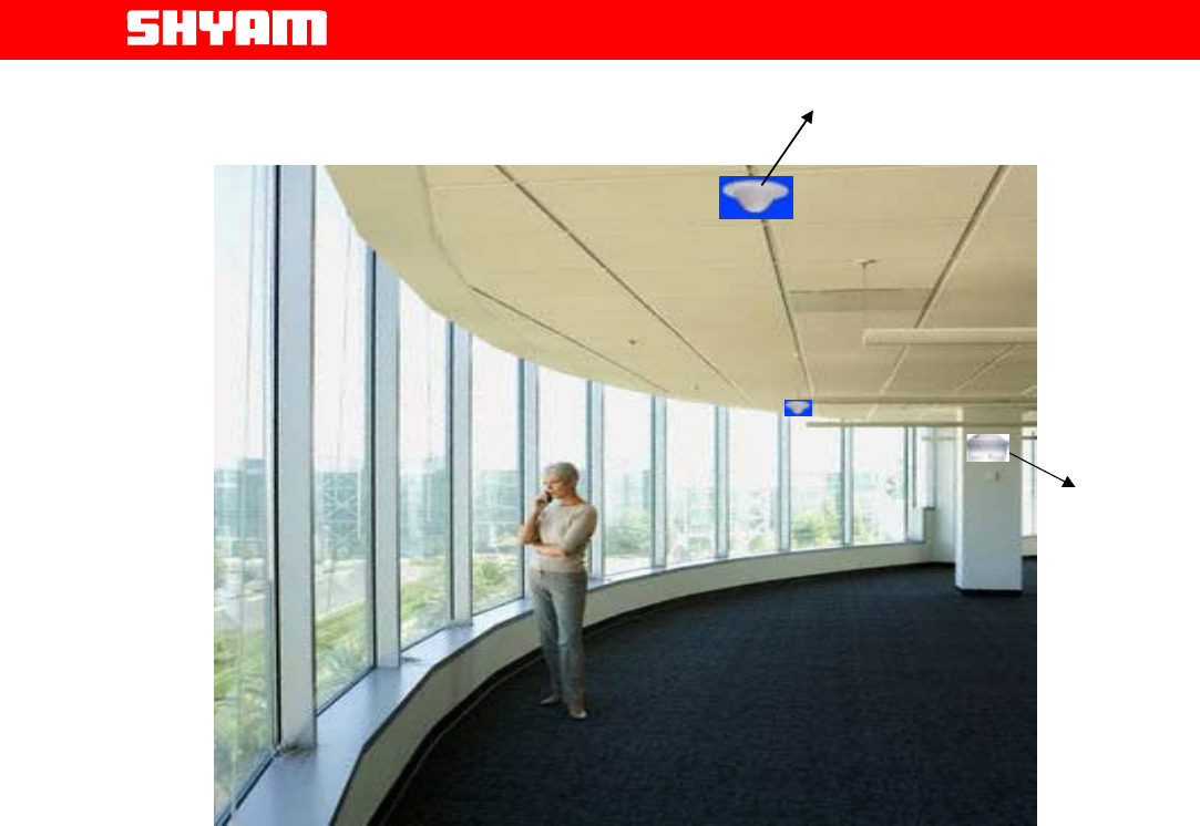
Ceiling
Antenna
Page
All Rights Reserved Shyam Telecom Limited 11/43
Next Generation
Signal Enhancement
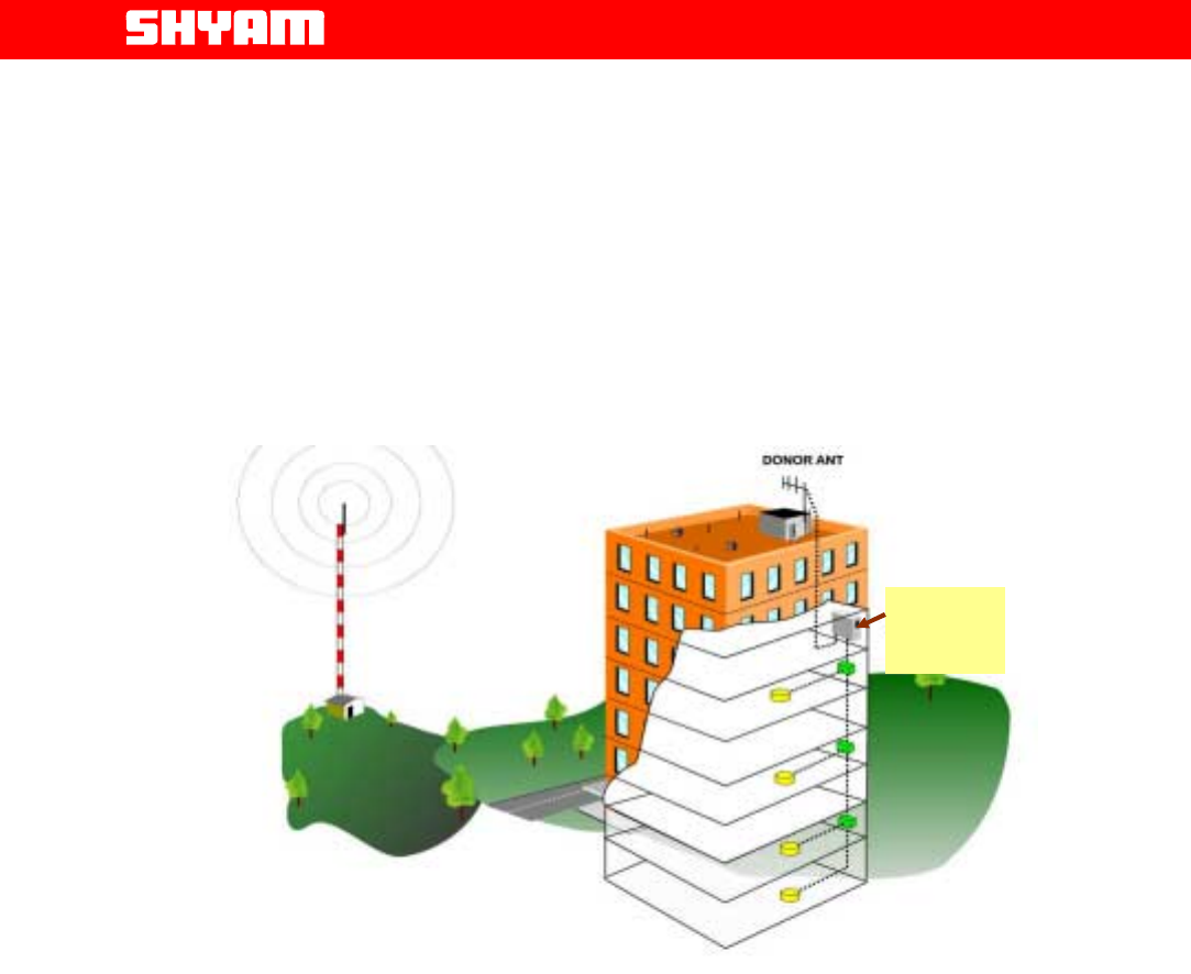
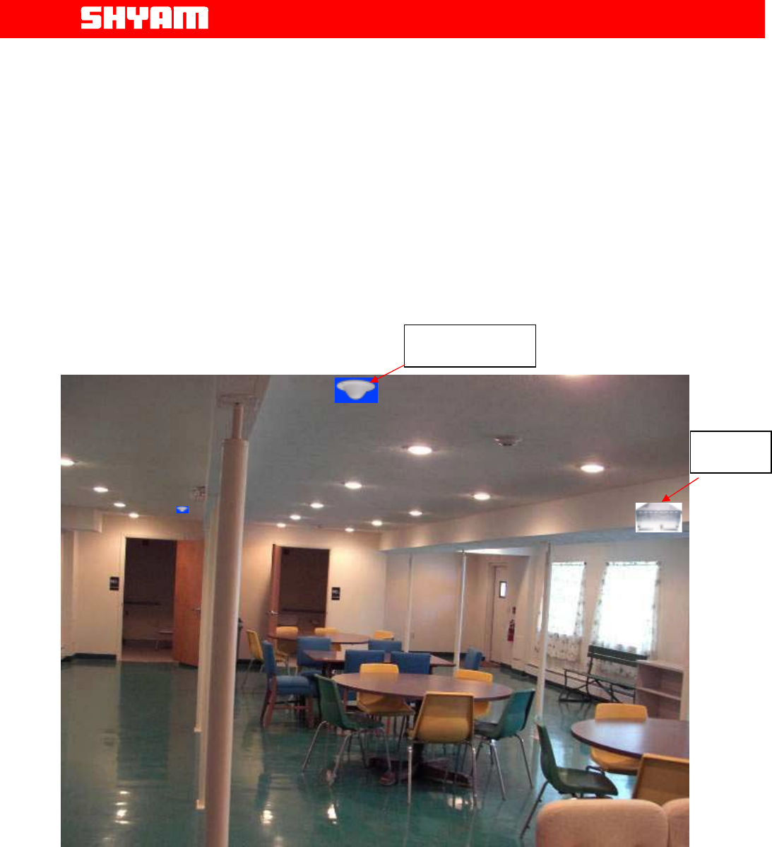
Figure 1: Typical In-building Coverage
5.2. Typical In-Building Coverage
The DB6MR20 repeater is designed to provide optimal coverage over an
area of approximately 1,000 to 2,000 sq. meters (10,000 to 20,000 Sq ft.).
However, ultimate performance depends on the obstructions
blocking/absorbing of the RF signals in side the building and the available
forward signal level at the donor antenna.
Typical coverage is usually planned for relatively small areas such as large
conference rooms or several adjacent rooms in smaller office areas.
Coverage is primarily determined by the available forward signal level at the
outdoor antenna input, loss due to the RF cable length, type of RF cable
installed and achievable isolation for optimum DB6MR20 performance.
Indoor coverage varies greatly due to the nature of various building
construction techniques and materials. Approximations of signal
level/coverage can be determined with the following assumptions:
• 10dBi to12dBi-donor antenna. Max. 9dBi indoor
omni/directional antenna.
DB6R20 unit
Page
All Rights Reserved Shyam Telecom Limited 12/43
Next Generation
Signal Enhancement
• Installed total cable and connector loss of approximately 5 dB
(125 feet of typical 1/2” coaxial foam cable).
• Interior building structure consists of typical vertical stud and
drywall composition.
• Isolation between the donor and server antennas should be 15
dB more than the gain of the repeater.
Figure 2: Application of DB6MR20 in a multi-storey building
DB6R20
Repeater
Page
All Rights Reserved Shyam Telecom Limited 13/43
Next Generation
Signal Enhancement
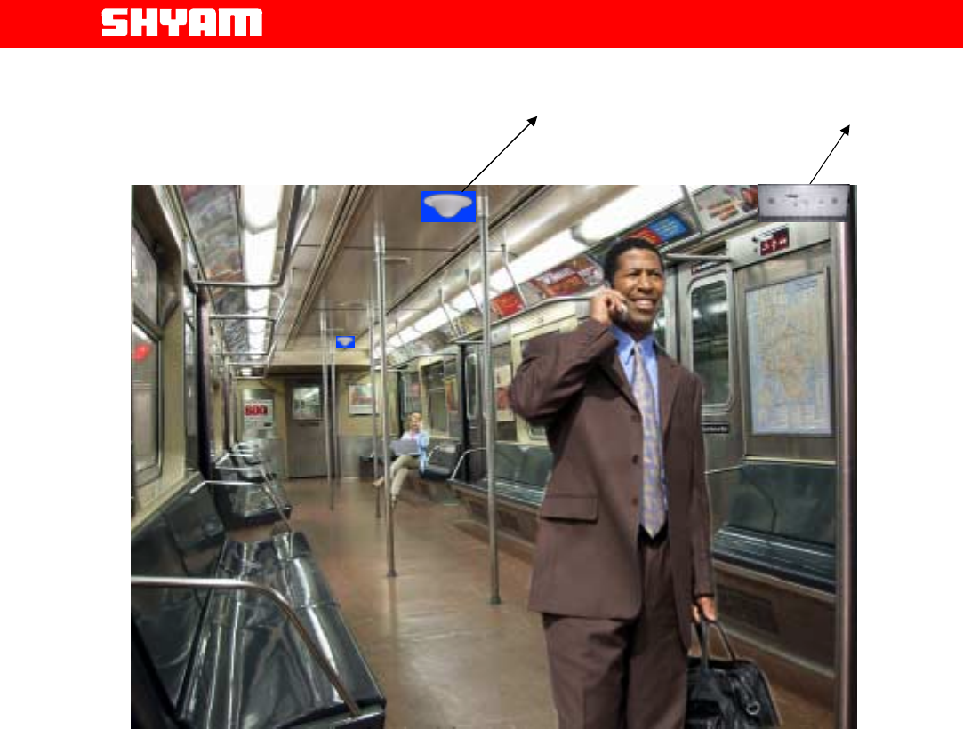
Figure 3: Typical Indoor Coverage Application in Train
Ceiling
Antenna
DB6MR20

Page
All Rights Reserved Shyam Telecom Limited 14/43
Next Generation
Signal Enhancement
6. To Get started-Basic Software Control of the System
6.1. General
The system is equipped with a supervisory module that allows the monitoring
and control of various parameters such as RF power, attenuation,
temperature, status of door and alarm conditions etc.
The communication interface between the local terminal and the control
module can be set up using the Configuration & Monitoring Console software
(CMC), which is an easy to use GUI for simple control and monitoring. It
enables monitoring of parameters & subsequent adjustment if required.
This function can be performed either using a terminal (PC/laptop) locally, or
through remote login using the wireless modem (Optional) located in the
repeater. USB port is provisioned in the equipment for connecting PC/laptop.
6.2. Terminal Set-up
The system is delivered with software loaded in order to perform configuration
as per requirement. The laptop/PC should be loaded with the CMC software
available on the supplied CD along with the USB driver.
Functions as described below are carried out through CMC software:
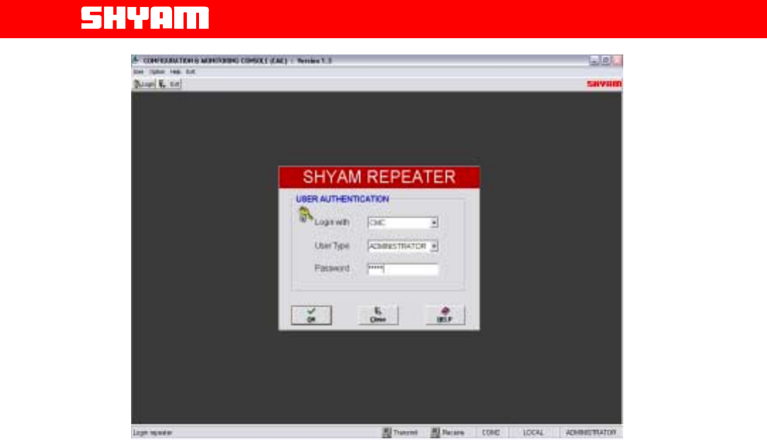
I) Login Repeater (Figure 4)
After running the Configuration & Monitoring Console (CMC), user needs to
login the repeater. To login the repeater:
• Click the “Login” on the command bar.
• Select the user type.
• Enter the password.
• Finally click the “OK”.
After successful login, a message “Logged in successfully” will be flashed
on the screen. Now user can start the operation through CMC.
There are two types of users viz. ADMINISTRATOR and SUPERVISOR. If
user logged in as an ADMINISTRATOR, all the operation through the CMC
can be carried out. The password by default is “SHYAM”.
SUPERVISOR is allowed to perform monitoring of the status & alarms but
no change in configuration is permitted. However, the SUPERVISOR can
change password if so desired.
Administrator can limit the system access authority of the SUPERVISOR.
Page
All Rights Reserved Shyam Telecom Limited 15/43
Next Generation
Signal Enhancement
Figure 4: Log-in Repeater
II) Configuration
Configuration means setting different repeater parameters for proper
operation. Configuration of Shyam repeaters can be performed locally with
a laptop / PC connected to the repeater by means of local USB serial
interface cable.
Clicking the CONFIGURE on the command bar, displays configuration
window. This window allows access to all the configurable repeater
parameters.
! SET: This is for updating the repeater parameters.
! READ: This is for reading configured parameters from repeater.
Repeater ID (Figure 5)
User can assign a unique repeater ID to each repeater installed. Up to 10
characters are allowed for this field.
Repeater Location (Figure 5)
User can assign the address of location where repeater is installed. Up to
30 characters are allowed for this field.
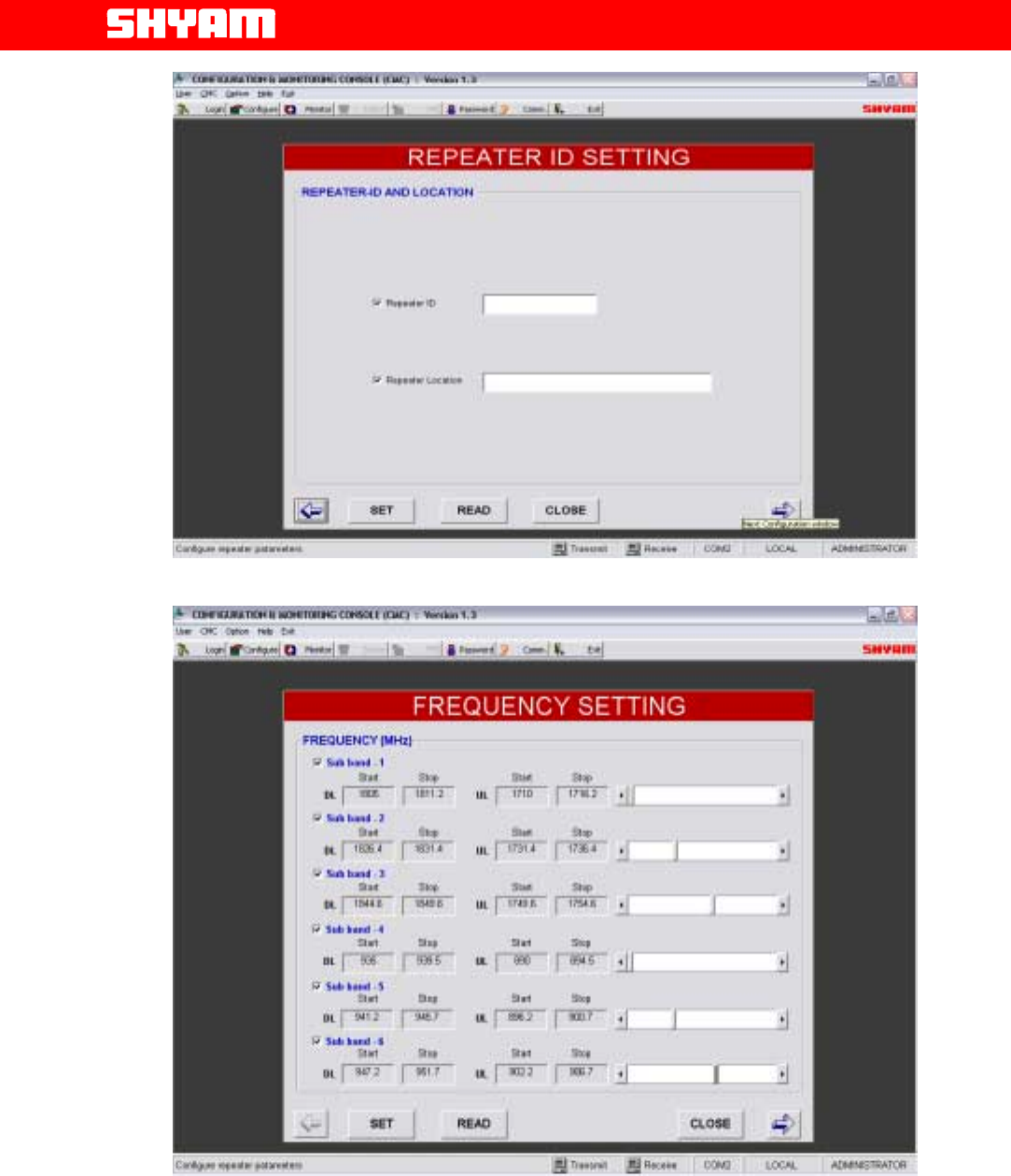
UP Link/ DL Frequency (Figure 6)
The UL /DL frequency ranges are defined for all the equipped sub bands
(Maximum up to six) depending on the bands being used.
Page
All Rights Reserved Shyam Telecom Limited 16/43
Next Generation
Signal Enhancement
Figure 5: Repeater ID/Location Settings
Figure 6: Frequency Settings in sub bands
Page
All Rights Reserved Shyam Telecom Limited 17/43
Next Generation
Signal Enhancement
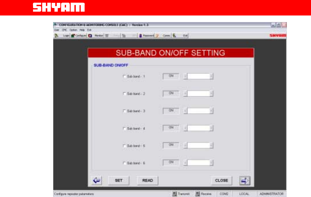
Figure 7: Sub Band ON/OFF Settings
Sub Band ON/OFF Settings (Figure 7)
Depending on the number of sub bands equipped, particular sub bands
can be configured as “ON” & others “OFF”. Maximum six sub bands can
be equipped.
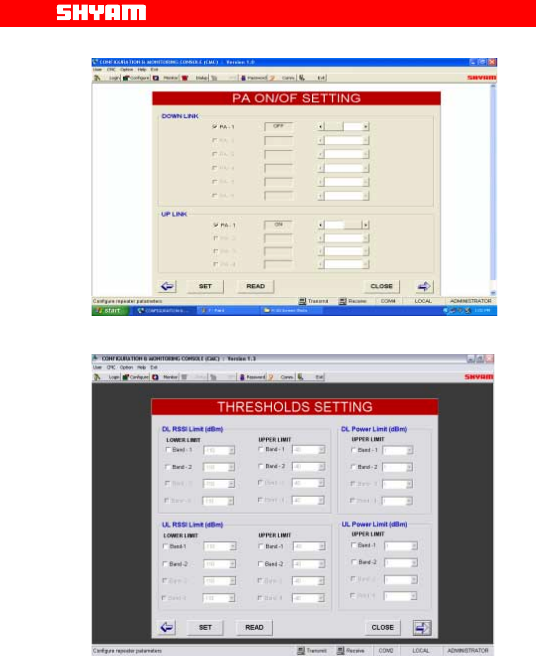
PA ON/OFF (Figure 8)
User can set UL and/or DL PA as ON or OFF independently for testing
purpose at the time of installation.
After completing the installation it must be in ON condition only.
Threshold Settings for Output Power (Figure 9)
Maximum Output Power limit in DL & UL paths are defined. PA Power
“High” alarm will be generated when PA power exceeds the upper limit.
RSSI limits (Figure 9)
Lower & High RSSI Limits in downlink & uplink paths are set in the factory.
A RSSI “High” alarm will be generated when RSSI exceeds the upper
limit, and a RSSI “Low” alarm will be generated when RSSI goes below
the lower limit set by user. Upper and lower ranges that can be set by user
vary from -50 to -80dBm.
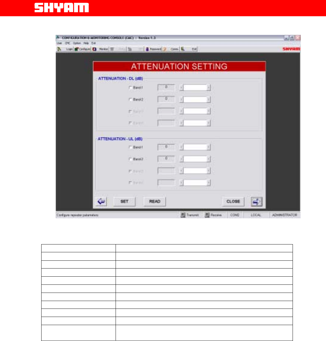
Attenuation Settings (Figure 10)
Through this setting, the attenuation is inserted in both the bands in UL &
DL paths as per the requirement of RF power. It is carried out when the
system is set in manual mode. In automatic mode whatever attenuation is
inserted, is displayed.
Page
All Rights Reserved Shyam Telecom Limited 18/43
Next Generation
Signal Enhancement
Figure 8: PA ON/OFF Settings
Figure 9: Threshold Settings
Page
All Rights Reserved Shyam Telecom Limited 19/43
Next Generation
Signal Enhancement
Figure 10: Attenuation Settings
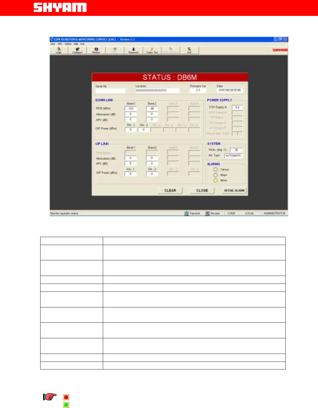
III) Monitoring (Refer Figure 11)
Parameter Remarks
Attenuation (Band 1 & 2) Displays UL/DL Attenuation inserted in the system in both the bands.
Output Power Displays PA output power in UL & DL paths in both the bands.
RSSI DL Real time RSSI DL signal strength in both the bands is indicated.
Location System location is displayed.
Serial Number Serial number (factory settable) is displayed.
Repeater ID
A unique repeater ID set by the user is displayed.
5.5 V power supply Value of derived Voltage is displayed
PA Temperature DL & UL Displays the temperature of PAs in DL & UL in both the bands
System Temperature Displays the temperature of the system
Alarms Displays if there is any alarm viz. critical, major or minor. Details can
be viewed by clicking at “DETAIL ALARM”.
Page
All Rights Reserved Shyam Telecom Limited 20/43
Next Generation
Signal Enhancement
Figure 11: Monitoring Status
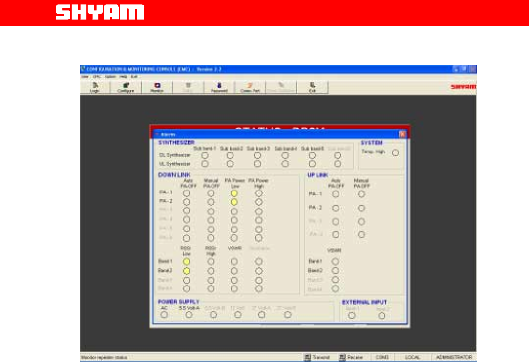
IV) Alarms (Refer Figure 12)
Observation Remarks
Synthesizer Fail (UL
& DL) Failure of synthesizer of a particular sub band either in DL or UL is
indicated by this alarm.
PA ON/OFF
(DL & UL) Indicates the status of PA if it is ON or OFF (manual/auto) to draw the
attention of the maintenance staff.
RSSI Low (DL) Indicates that the RSSI has exceeded the lower limit set.
RSSI High (DL) Indicates that the RSSI has exceeded the higher limit set.
PA Power Low (DL) When PA Power goes below the lower limit set by the user, this alarm is
generated.
PA Power High (DL) When PA Power exceeds the upper limit set by user, this alarm is
generated.
PA Temperature High
(DL & UL) Indicates the rise in temperature beyond the safety limits.
VSWR (DL & UL) Indicates when VSWR exceeds the specified limits (1.5:1) due to
mismatching.
LNA (DL &UL) Failure of LNA is indicated
System Temperature Indicates the rise in temperature of system.
Monitoring interval is 3 seconds i.e. after every 3 seconds data on the monitoring
window will be refreshed.
A red indication is for Alarm present.
A green indication is for No alarm.
Page
All Rights Reserved Shyam Telecom Limited 21/43
Next Generation
Signal Enhancement
Figure 12: Display of Alarms
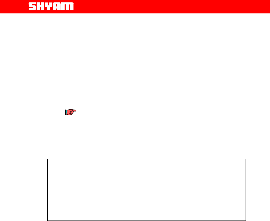
V) Communication (Figure 13)
In COMMUNICATION window user can select serial communication port
of the computer and type of connection between repeater and computer.
There are two types of connections viz. Local and Remote
a) Local Connection
In this type of connection, user computer COM Port and repeater’s
USB Port are connected directly using cable. Steps as indicated
below, are followed:
• Click the “COMM.” on the command bar to display the
COMMUNICATION window.
• Select the Connection Type as “LOCAL”
• Select the computer’s Comm. Port where the repeater is
connected.
• Click “OK”.
b) Remote Connection
In this type of connection, User communicates from/to remote location
with the repeater using wireless Modem / Cell phone.
To connect:
• Click the “COMM.” on the command bar to display the
COMMUNICATION window.
Page
All Rights Reserved Shyam Telecom Limited 22/43
Next Generation
Signal Enhancement
• Select the Connection Type as “REMOTE”.
• Select the computer’s Comm. Port where the wireless Modem
is connected.
• Click “OK”.
• Now click the DIALUP on the command bar to display the
DIALUP window.
• Enter / Select the repeater phone number.
• Click the “DIAL” and wait (maximum 60 seconds) for
connection.
A message “CONNECTED” will appear on the screen after the modem
Connection is established.
Click the “DISCONNECT” on the DIALUP window to disconnect
remote communication with the repeater.
Wireless Modem (Optional) is equipped inside the housing of the
repeater and it can be easily located through a sticker provided on the
same. It has a groove with SIM cardholder in which the SIM card can be
inserted for remote communication.
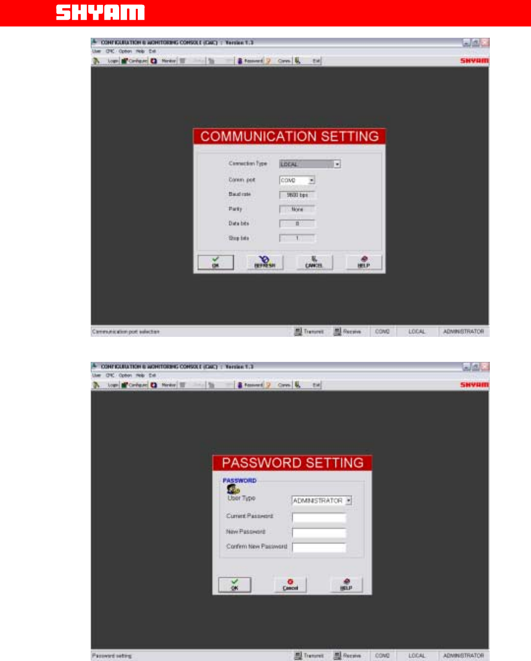
VI) Security (Figure 14)
The system has been incorporated with “Security” to protect the
settings and to avoid unauthorized access. It is through a Password,
which can be set/reset. Click the Password on the command bar to
display Password Setting window where administrator can change
password.
CAUTION
When the communication between repeater & PC/Laptop is in progress
through USB:
1. Do not remove cable from the USB port.
2. Do not switch off the repeater.
In case the communication is not required any more, click at EXIT before
removing cable from USB port to avoid hanging of the PC/Laptop. In case
the PC/Laptop goes in to hanging mode, it has to be restarted after
closing/switching OFF & ON the repeater.
Page
All Rights Reserved Shyam Telecom Limited 23/43
Next Generation
Signal Enhancement
Figure 13: Communication Setting
Figure 14: Password Settings
Page
All Rights Reserved Shyam Telecom Limited 24/43
Next Generation
Signal Enhancement
6.3. Block Diagram Description
The signals intercepted through the Donor antenna in the DL pass through
different devices for further signal processing.
Figure 15: Block Diagram DB6MR20 Repeater (3+3 Configuration)
(see separate document)
a. DONOR Antenna
Donor antenna of appropriate bandwidth & gain interfaces the BTS on one
side and repeater system on other side through RF cable. It is used to
receive signals from the base station and transforms electromagnetic
waves into RF signals in the DL and vice versa in the UL.
The antenna with no more than 10dBi to 12dBi gain transfers received
signals to the repeater and transmits uplink signals amplified by the
repeater.
Figure 16: A Typical Donor Antenna
b. Quad-plexers
Two Quad-plexers are equipped in the repeater, one on the BTS side &
other on the server side. The functions are:
• To isolate frequency bands corresponding to DL & UL paths
• To segregate frequencies corresponding to two service bands
equipped in DL & UL paths
Refer to Figure 15
c. Low Noise Amplifier (LNA)
This module is provided after each quad-plexer in the repeater before the
converter. The LNA provides compensation for the losses suffered by the
Page
All Rights Reserved Shyam Telecom Limited 25/43
Next Generation
Signal Enhancement
stream of weak signals as it passes through passive devices. Four LNAs
are provided, two each for individual bands in the UL & DL directions.
d. Converter
The basic block of converter is comprised of L.O., frequency mixer, filter
and intermediate amplifier. The low noise amplified signals are converted
to IF in frequency mixer with frequency fed from LO. The signals are
passed through sharply tuned filters. Number of converters equipped shall
depend on the number of sub bands configured in the system. Two
converters (one for DL & one for UL) for each sub band are provided.
f. Power Amplifier
It is the core module of repeater. It includes driver stage and final stage. It
is installed directly on the heat sink of the repeater. Driver stage and final
stage of power amplifier are in the same unit. Four power amplifiers with
specific frequency bandwidths & gain are provided, two each for individual
bands in the UL & DL directions.
g. Supervisory
The man-machine communication between the user and the repeater is
established through this module. One of the two options as given below
can be used for achieving this objective:
• USB interface
• Wireless modem (Optional)
Remote controlling function of repeater can be achieved by inserting
Wireless modem. This arrangement also enables status of repeaters at
different locations to be monitored.
h. POWER SUPPLY
The power supply unit incorporated in the repeater is of high efficiency
and reliability. Different DC voltages required for the operation of
electronic circuitries are derived in this unit. The standard input voltage is
100 to 240 V AC, 47 Hz to 63 Hz. When the power supply varies in this
range and the frequency in 47 to 63 Hz, its output DC derived voltages
remain constant within 1% of nominal value.
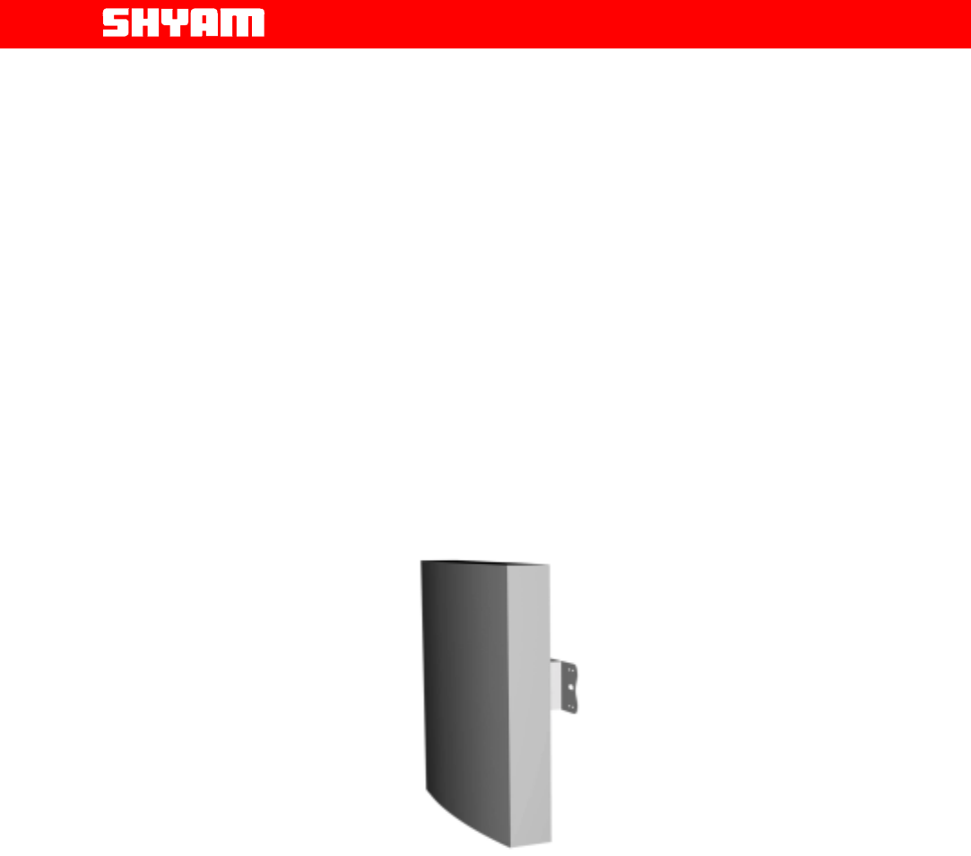
i. SERVER Antenna
Server antenna transmits signals from the repeater station to mobile users
and transport received uplink signals from the mobile users to the base
station. Based on the coverage area, a set of select omni/directional
antenna(s) having proper gains ( less than 9dBi) with connecters may be
installed at pre-planned spots.
Page
All Rights Reserved Shyam Telecom Limited 26/43
Next Generation
Signal Enhancement
Figure 17: Typical Server Antennas
7. DB6MR20 Repeater Specifications
7.1 Specification-RF
S.N0.
Parameter Specified limits
1. Number of Bands Two, one each in 800/900 MHz &
1800/1900/2100 MHz frequency
bands or as per requirement of the
customer.
2. Frequency band uplink Customized as per requirement of the
user.
3. Frequency band downlink
Incorporated as per requirement of
the customer in accordance with
frequency set for uplink.
4. Number of Sub bands Six with 3 sub bands in each band
with 3+3 configuration or as per
requirement.
5. RF output power in DL +19dBm±1dBm (P1 +26dBm)
6. Gain 85.0dB±3dBm
7. Spurious Emission <-36dBm @ 9KHz to 1GHz &
< -30dBm 1GHz to 12.75 GHz
8. Gain variation over temperature + 1.5 dB over normal temperature
range
9. Attenuation range for
adjustment of gain in UL & DL
paths in both bands
0 to 31dB in steps of 1 dB (Software
control)
10. Noise figure 5 dB
11. Propagation delay/direction in
the signal path < 5.5 us
12. Impedance at RF ports 50 Ohms
13. Return Loss 16 dB
14. Remote control & management Through optional wireless modem
15. Automatic Power Control 10 dB
7.2. Electrical Specification Power Requirement
Parameters Specified/Limits
Input AC Voltage Range 100-240 V, 47/63 Hz
Power Consumption Approx.
80 watts (Shall vary depending on the number of
sub bands equipped)
Page
All Rights Reserved Shyam Telecom Limited 27/43
Next Generation
Signal Enhancement
7.3. External Electrical Interface
Parameters Specification
RF port UL N-type (F)
RF port DL N-type (F)
7.4. Mechanical Specification
Dimensions (w x h x d) 520x400x180 mm (20x15x7 inches)
Weight Approx. 20 Kg. (44 lbs.)
Housing Indoor application
Housing Color Grey
Cooling Convection
7.5. Environmental Specification
Conditions Specification
Operating Temperature -5oC to +50 0C (+230F to +1220F)
Storage Temperature -300C to +750C (-220F to +1670F)
Enclosure In accordance with indoor applications
7.6. Contents of Delivery
ITEMS
QUANTITY
Repeater
unit
DB6MR20
–
Model as per
requirement
1
PC interface cable for USB port
1
Power cable with 3 pin plug
1
Operation & Installation manual
1
CD containing the application software
1
Wireless Modem (Optional)
1
Page
All Rights Reserved Shyam Telecom Limited 28/43
Next Generation
Signal Enhancement
8. Installation
8.1. Preparation Sheet-Pre Installation
Before the commencement of installation, a preparation sheet is compiled for
expected performance & better maintenance.
1. General
Application: Indoor
Service Band 1: Frequency Band DL- UL-
Service Band 2: Frequency Band DL- UL-
Number of Sub Bands: Six
Sub Band 1: Frequency Band DL- UL-
Sub Band 2: Frequency Band DL- UL-
Sub Band 3: Frequency Band DL- UL-
Sub Band 4: Frequency Band DL- UL-
Sub Band 5: Frequency Band DL- UL-
Sub Band 6: Frequency Band DL- UL-
2. Technical requirements
S.NO. Requirement Remarks
1. Estimated RF Power available at site where
donor antenna is to be installed
2. Estimated Cable loss from donor antenna to
the repeater unit
3. Estimated Downlink RF power to the input of
the repeater
4. Desired RF Power in DL
5. Proposed Gain settings in DL path
6. Proposed Attenuator inserted in DL path
7. Estimated Cable loss from repeater unit to
server antenna port
8. ERP at server antenna
9. Desired RF Power in UL
10. Proposed gain settings in UL path
11. Proposed Attenuator to be inserted in UL path
3. Proposed site Address: ---------------------------
4. User’s Address & other particulars: ---------------------------------

Page
All Rights Reserved Shyam Telecom Limited 29/43
Next Generation
Signal Enhancement
Date: Prepared by: -------------
8.2. Engineering Consideration
a. Site Selection
Site selection is one of the most critical decisions affecting the overall
performance of the system. A repeater must be located where it can
receive the maximum signal strength from the donor site in order to
maximize the repeater’s output and performance, signal strength greater
than or equal to -75dBm is desired.
Examples of donor antenna locations include (but are not limited to): the
roof of a building adjacent to the affected area, with the antennas mounted
on the highest point in the building; the top of the hill that is obstructing the
donor site’s coverage, with the antennas mounted on poles at ground
level; a water tower with antennas mounted at the top or as the situation
permits.
Distance from both the donor site as well as from the new area to be
covered must be taken into consideration. The repeater unit should be
located close to the donor site so as to receive adequate signal strength
and at the same time it is located in the vicinity of area where coverage is
desired. In addition, the donor antenna associated with the repeater unit
should have line of sight with BTS site to reduce the effects of fading.
Another important aspect when choosing a repeater location is the
availability of AC for operation of the system. Sites where repeater unit is
installed should be easily accessible for the maintenance team.
b. Antenna Selection and Placement
Proper selection of the repeater’s donor and server antennas is crucial in
designing the repeater system. Appropriate antenna characteristics help
to provide proper isolation between the server (coverage) and donor
antennas, which helps to prevent feedback. An isolation of at least 15 dB
more than the gain setting of the repeater is maintained to avoid the
possibility of oscillations.
Specific ways to achieve proper isolation include: using high gain
directional antennas with good Front to Back ratios (25dB or better);
physical separation of the repeater’s donor and server antennas; and
external shielding between antennas. A high gain antenna will help
minimize overall path loss to achieve the desired output power. Donor
antenna gains are typically 10 to 12 dB, while server antennas with gains
as per requirement are deployed.
• The antennas should have proper frequency band of operation.
• Adequate separation is to be ensured from the power lines to
avoid damage to the equipment and humans.
Page
All Rights Reserved Shyam Telecom Limited 30/43
Next Generation
Signal Enhancement
• Antenna with proper characteristics to maintain adequate isolation
to avoid oscillations. Normally, isolation should be 15 dB more
than the gain set for the repeater. It should have good front to
back ratio.
• The beam width for the DONOR antenna should be as small as
possible.
• The beam width for SERVER antenna is 60 degree to 120 degree.
• There should be adequate vertical & horizontal separation
between the DONOR & SERVER antennas to avoid interference
and noise.
Separation can be determined by the mathematical formulas:
Vertical Separation:
Isolation (dB) = 28 + 40 log (D/λ in meters)
Horizontal Separation:
Isolation (dB) = 22 + 20 log (D/λ in meters) – (Gain of donor
antenna + gain of server antenna)
D-Distance between donor & server antennas in meters
λ- Wave length in meters
The following table is an approximate guide to antenna separation.
The use of highly directional antennas with good front to back ratios can
help to achieve isolation requirements.
A Typical Example
Vertical Separation
Separation (m.) Isolation (dB)
5 75.0
10 87.1
20 99.1
30 106.2
40 111.2
50 115.0
Horizontal Separation
Separation (m.) Isolation (dB)
5 45.5
10 51.7
50 65.5
100 71.5
150 75.1
250 77.6
Vertical and Horizontal Antenna Separation @ 900 MHz
The antenna separation table demonstrates that vertical separation yields
better results than horizontal separation. However, when desired isolation
cannot be met due to insufficient separation, external shielding can help; for
example, mounting the antennas on either side of a rooftop penthouse or

Page
All Rights Reserved Shyam Telecom Limited 31/43
Next Generation
Signal Enhancement
using some type of grounded metal screen or wire mesh (so called chicken
wire) between antennas.
The following example illustrates a typical signal level at input of the
repeater and other losses with final EIRP:
Received Signal Level -62 dBm
Donor Antenna gain 12 dBi
Cable loss (100 ft. of 7/8 inch) 2 dB
Input to Repeater -52 dBm
Gain of Repeater set 70 dB
Output of Repeater +18 dBm
Cable loss (100 ft. of 7/8 inch) 2 dB
Server Antenna Gain 7 dBi
Repeater EIRP +23 dBm
c) Overlapping Coverage
Ideally, the repeater system will be engineered with minimal overlapping
coverage between the donor base station and the repeater. However, the
mobile will occasionally receive signals from both the donor and the
repeater at similar levels. This situation is comparable to a mobile receiving
multiple signals at varying times due to multi-path propagation.
The repeater contributes a maximum signal delay of 5.5 microseconds in
each direction.
d) Call Processing
The mobile communication system perceives calls handled by the repeater
as actually being handled by the donor site (BTS); the repeater is just an
extension of the base station’s coverage. Therefore, the donor handles call
initiation, power control messages, hand-over requests, etc., for mobiles in
the repeater area. When the base station assigns a channel to the mobile,
that channel is sent through the repeater and then reradiated under the
same frequency. Since the repeater is technically part of the base station,
no hand-over takes place when a mobile moves from the repeater’s
coverage area to that of the base station. When the mobile moves from the
repeater’s area to a neighboring site, the base station handles the hand-off
in the same way as for a mobile in the base station area.
8.3. Installation Tools
You will need the following basic tools for installation:
a. Standard wrenches/screwdrivers/cable stripper/cable cutter/pliers set
for installing the DB6MR20 Unit and antennas. (Refer to the
manufacturer’s recommendations for installing the antennas).
Page
All Rights Reserved Shyam Telecom Limited 32/43
Next Generation
Signal Enhancement
b. RF cable connecting tool for installing connectors.
c. Multi-meter.
d. Mobile handset loaded with NET engineering software to be used for
signal level measurement.
e. Magnetic compass for measuring the azimuth of the BTS and
repeater site.
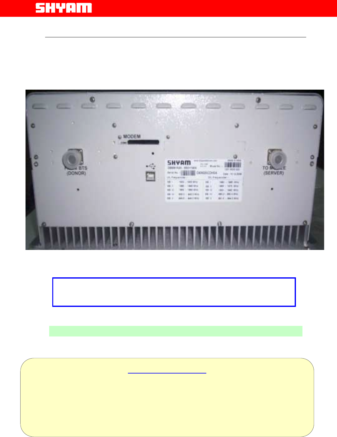
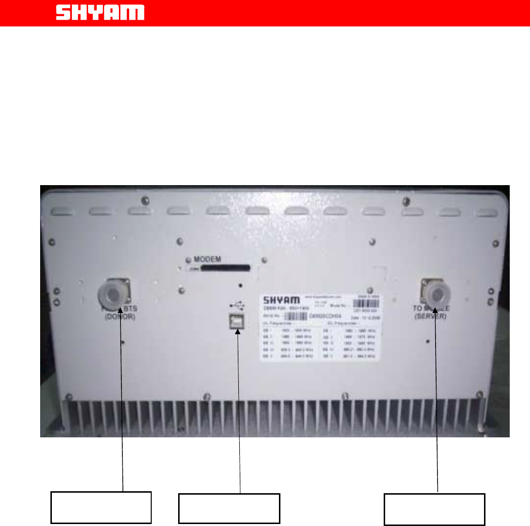
Figure 18: Connections at ports
8.4. Installation Procedure
1. RF cable installation must comply with local or National Electrical Codes.
The cable shall have nominal 50-Ohm impedance. Pull and route the RF
cables as per the site installation plan.
2. Fix the supplied connectors to the RF cable and verify the following:
• The center conductor to outer shield of RF coaxial cable indicates
“Open Circuit” condition.
• Check for any short circuit between center conductor and outer
shield.
Donor Antenna
Port
USB Interface port
Server Antenna
Port

Page
All Rights Reserved Shyam Telecom Limited 33/43
Next Generation
Signal Enhancement
• Place short between the center conductor and outer shield using
a piece of wire temporarily and check the other end of conductor
for any break in the RF cable.
3. Mount the DB6MR20 unit on the intended wall surface using the
appropriate screws.
4. Install the indoor coverage antenna according to the antenna
manufacturer’s instructions. Connect the RF cable between the indoor
antenna and the “MS” port on the DB6MR20 unit.
5. Install the donor antenna (Outdoor antenna) according to the antenna
manufacturer’s instructions. Connect the RF cable between the donor
antenna and the “BTS” port on the DB6MR20 unit.
8.5. Gain Settings
The repeater gain is one of the vital parameters since it also decides the
area to be provided with RF coverage. The noise contribution has to be
minimum while the gain is set.
Signals received by DONOR antenna from BTS and transmitted to the
repeater are termed as DL/Forward signals and the signals originated by
mobile users and intercepted by SERVER antenna for application to
repeater are termed as UL/Reverse signals.
a. Forward Gain Setting
The process of setting the forward gain is carried out automatically (in
automatic mode) through software depending on the threshold settings for
RSSI & maximum RF power.
In manual mode, the setting is carried out through software by observing
the forward signal level strength with any mobile handset loaded with
engineering software.
Alternatively, RSSI can also be observed through LEDs provided on the top
of the cover of repeater.
Once the RF output power has been determined, the attenuation will have
to be modified to reach the desired output signal level.
The gain of repeater can be set using any of the following methods:
a. Local USB serial interface mode (GUI based)
b. Remote through (optional) wireless modem.
b. Reverse Gain Setting
For reverse gain setting, 31dB variable attenuator is inserted in
accordance with the attenuation inserted in the DL.

Page
All Rights Reserved Shyam Telecom Limited 34/43
Next Generation
Signal Enhancement
8.6. Commissioning
Important:-Repeater should not be connected to Power without
termination at the antenna ports. The termination can be carried out
either by the antenna connection as well as a dummy load or the 50
Ω
terminated connection of a measuring instrument (Power Meter,
Spectrum analyzer with appropriate PAD)
1. Plug the power cable to the AC mains and switch ON the unit.
2. Once the repeater is ON, the LEDs will not glow under normal condition.
3. The UL Align indication LED and DL align indication LEDs will blink for
adjusting the DL gain and UL gain automatically.
4. Review the intended coverage area according to the site installation plan.
Measure & monitor signal level at various points within and around the
perimeter of the coverage area with a mobile handset loaded with NET
engineering software and the SIM card of cellular operator.
Page
All Rights Reserved Shyam Telecom Limited 35/43
Next Generation
Signal Enhancement
8.7. Checklist – Post Installation
After completion of installation, points as stated in the checklist may be verified
to ensure that all aspects have been covered.
Service Bands Particulars:
Frequency Band for Band 1 DL
Frequency Band for Band 1 UL
Frequency Band for Band 2 DL
Frequency Band for Band 2 UL
A. Repeater Installation
S.NO. Point(s) To be Verified Remarks
1. Ensure isolation between server and donor
antennas, it has to be 15 dB + Gain set of the
repeater.
2. Actual isolation measured
3. Ensure proper grounding of the unit
4. Cable from donor antenna connected to donor
antenna port
5. Cable from server antenna connected to the
relevant port in the unit
6. Mains cable connected to the repeater unit
7. Cable protection ensured and outdoor connections
are waterproof
B. Repeater Set Up
S.NO. Point(s) To be Verified Remarks
1. Number of sub bands equipped
2. Number of Sub band(s) in Band 1 with frequency
bandwidth of each.
3. Number of Sub band(s) in Band 2 with frequency
bandwidth of each.
4. Repeater switched ON
5. Any error (alarms) observed
6. Gain set
7. Power level in DL
8. Attenuation in DL
9. Power level in UL
10. Attenuation in UL
11. Observation on CMC software & GUI

Page
All Rights Reserved Shyam Telecom Limited 36/43
Next Generation
Signal Enhancement
12. Repeater secured & locked
Any Other Remark/Comment:
Date of Installation: ------------------------ Repeater ID & Site Address: ----------------
Name of the Installer: -----------------------------------------------------
8.8. Dos & Don’t Dos
1. The site should be accessible for maintenance purposes.
2. Arrangement is to be made to avoid unauthorized access to the
repeater.
3. For indoor applications, the housing should be kept away from direct
exposure to the Sunlight & chemical fumes.
4. Stable power supply for repeater unit should be ensured.
5. The route of Cables to/from antennas should be short to minimize the
cable losses and should be free from sharp bends & kinks.
6. There should be adequate separation between antenna system and
power lines to avoid damage to system and humans.
7. Local standard of cabling should be followed.
8. The donor antenna should have proper line of sight with the BTS from
where the signals are to be intercepted for maximum signal strength
and to reduce the effect of fading.
9. The selection of BTS should be made taking other BTSs in the same
vicinity in to consideration to avoid interference.
10. Gain of the repeater should be set after taking antenna isolation in to
consideration.
11. The estimation of coverage area should be confirmed.
12. The system should be made over for normal traffic after actual
measurement of:
a) RF power in the DL
b) RF power in the UL
c) Antenna Isolation
d) Gain settings in DL & UL
13. Feedback regarding performance of the system may be sent to Shyam
Telecom by the user.
Page
All Rights Reserved Shyam Telecom Limited 37/43
Next Generation
Signal Enhancement
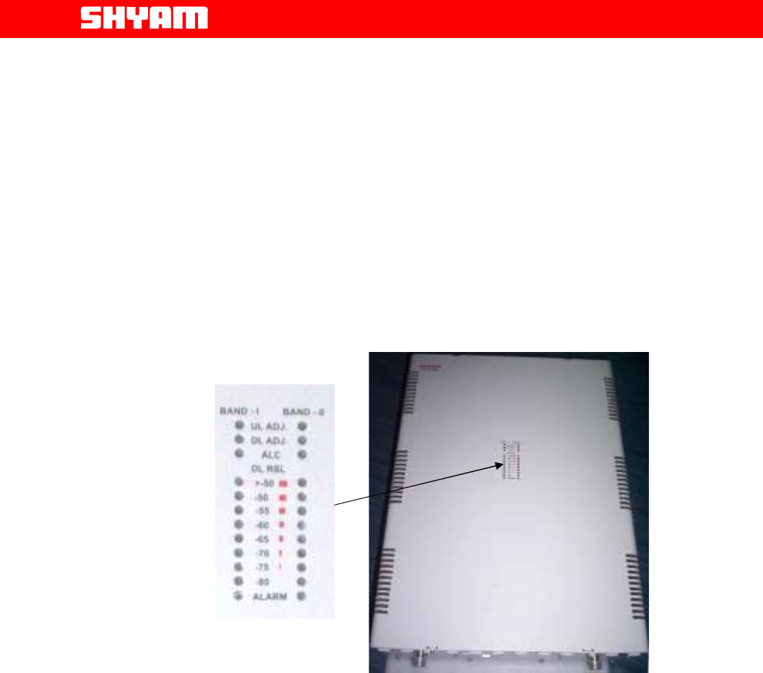
8.9. Display Details of DB6MR20
In order to display the status prevailing in the system, LEDs are provided on
the top cover of the housing. These LEDs display the conditions in both the
bands.
Figure 19: LED Display on DB6MR20
• UL ADJ. will blink when system is in Uplink Alignment mode.
• DL ADJ. will blink when system is in Downlink Alignment mode.
• ALC LED will blink when, when system is in ALC.
• Alarm LED will Glow when the system goes to the shut down mode due to
input power going/out put power going high (beyond ALC) in DL path.
• Downlink RSSI is continuously monitored and level is displayed through 8
LED’s.

Page
All Rights Reserved Shyam Telecom Limited 38/43
Next Generation
Signal Enhancement
9. System Maintenance
9.1. General
The system normally operates without any operator intervention or
maintenance. In the event of fault, the field replaceable units (antenna &
cables) should be checked for faults and the system restored if possible. A
faulty unit can be removed and replaced with a spare while the rest of the
system is still operating. Soldering or local repair of the modules should be
avoided. Faulty module/unit should be replaced with genuine spares from
Shyam Telecom Limited only.
However, the power supply of the faulty unit should be isolated from AC
mains and DC power before any module is replaced. In the event of a
system malfunctioning, the status of the antenna systems should be
checked as well as the continuity of the cabling before replacing any
modules within the repeater.
9.2. Preventative Maintenance
The DB6MR20 repeater does not require any preventative maintenance.
9.3. In-Building Coverage Problems
If the coverage area appears to be smaller than the installation site plan,
there are only a few possibilities that limit the signal level in the area.
I) Physical obstructions degrading the signal level-Visually inspect the
area of weak coverage. If possible, rearrange objects that may be
interfering with the signal path. Pay particular attention to large metallic
objects that reflect or block the signals to the weak coverage area. If
weak coverage area still persists, check the following:
a. Inspect the indoor RF coaxial cable and its connection with
connector
b. Indoor antenna direction and its tilting
c. DB6MR20 repeater gain setting
II) Defective Indoor coaxial cable/Antenna – Check the RF coaxial cable
and antenna. If necessary, replace each individually with a known
functional unit, and verify the respective signal level. This can be
achieved by observing the signal strength indicator on a mobile handset
that has an unobstructed line-of-sight view, 15 to 20 feet (5 to 7 meters)
from the indoor antenna. If the signal level increases at this test location,
re-verify the signal level in the weak coverage area. If the signal level
remains marginal, inspect the unit.

Page
All Rights Reserved Shyam Telecom Limited 39/43
Next Generation
Signal Enhancement
III) Defective Unit – Replace the unit with a known operational unit. Verify
the signal level at the unobstructed test location. If the signal level
increases, re-verify the weak coverage area. If the weak coverage area
remains marginal, an additional indoor antenna or DB6MR20 may be
required to cover the additional area. If the unit is found to be defective,
please contact our Technical support team. The unit serial number must
be available to establish a return authorization. If replacing any part,
Shyam authorized service dealer should replace it and no soldering/
repairing of PCBs should be carried out in the field for reliable service
thereafter.
IV) Signal Quality Problems
Under certain conditions, the signal level on the mobile handset may
indicate adequate signal strength, but the quality of the signal is
degraded (i.e. distortion).The signal level at the donor antenna is
probably too strong. Under these conditions, the service provider’s
exterior signal level is adequate, in such condition, reduce the forward
path signal using the forward attenuation in the repeater and minimize
the forward signal level in step of 1dB until the problem subsides.
But ensure that the In-Building signal level remains adequate for the
coverage area.
V) Antenna Isolation
Antenna isolation is defined by the path loss or attenuation, between the
donor and server antennas. It is important to ensure that the antennas
are sufficiently separated, such that the signal transmitted by donor
antenna is not received by server antenna and vice versa. For optimal
performance, the separation of the two antennas must provide a path
loss of at least 15 dB greater than the set gain of the repeater.
In most cases, isolation will be achieved by properly locating the donor
and server antennas, respectively. The optimal location for the donor
antenna is high above the roofline, and exterior to the building. The
indoor coverage antenna (server) should be installed inside, near or
below the ceiling. Following guidelines should ensure adequate isolation
between antennas.
a) Never mount the donor or server antenna near a window, where
signals can easily pass through the glass.
b) Mount the donor antenna as high as physically possible to the exterior
of the building, maximizing the vertical separation between the donor
and server antennas. The donor antenna should point towards the
base station site.
c) Install the antennas taking advantage of any existing building structure
such as brick walls, metal roofs, or multiple wall structures to
additionally attenuate the path between them.
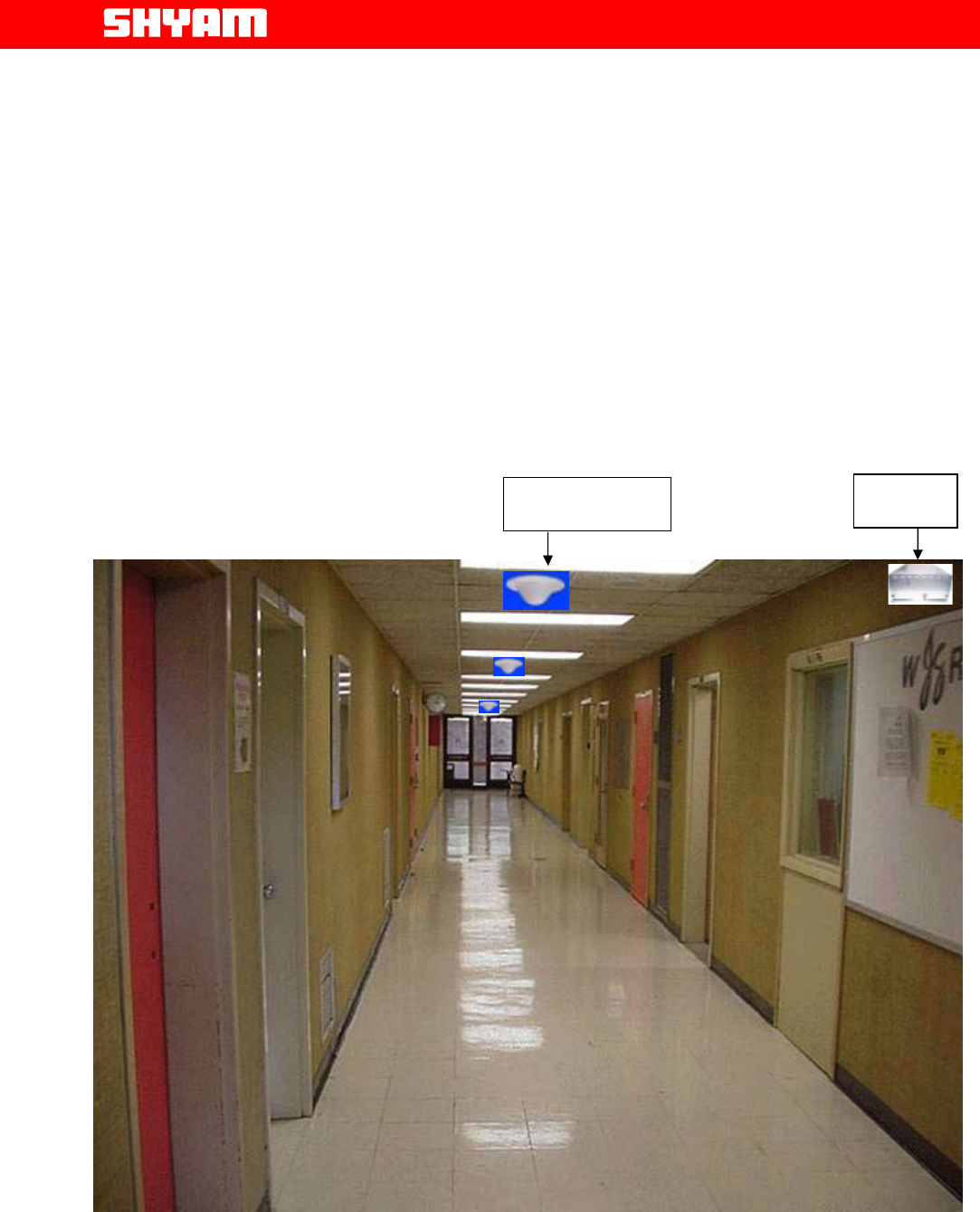
d) Whenever using directional antennas inside the building to cover
corridors and hallways, point the indoor antenna away from the donor
antenna location.
e) In extreme cases, the building configuration may not allow for such
separation and isolation. If additional isolation is required, coaxial
Page
All Rights Reserved Shyam Telecom Limited 40/43
Next Generation
Signal Enhancement
attenuator may be inserted between the donor antenna and the
repeater or reduce the forward path signal using the attenuation
control with the likely compromise to the overall coverage within the
building.
TYPICAL PRODUCT APPLICATION
Figure 20: Indoor Application of DB6MR20 in a room
DB6R20
Celling Antenna
Page
All Rights Reserved Shyam Telecom Limited 41/43
Next Generation
Signal Enhancement
Figure 21: Indoor Application DBR6R20 in a Corridor
DB-6R-20
Ceiling Antenna

Page
All Rights Reserved Shyam Telecom Limited 42/43
Next Generation
Signal Enhancement
FCC Statement:
FCC ID:S3CDB6MR20
This device complies with Part 2, 22,24 of the FCC Rules. Operation is
subject to the following two conditions: (1) this device may not cause harmful
interference and (2) this device must accept any interference received, including
interference that may cause undesired operation.
IC Statement:
Trade Name: SHYAM Dual Band Inddor Repeater
Model No.: DB6MR20
IC: 5751A-DB6MR20
This device complies with RSS-131, RSS-102 of the IC Rules.
Warning
Changes of modifications not expressly approved by the manufacturer could void
the user’s authority to operate the equipments.
Antenna Information:
This device has been designed to operate with the antennas listed below, and having a maximum
gain of 12dBi. Antennas not included in this list or having a gain greater than 16dB are strictly
prohibited for use with this device. The required antenna impedance is 50 ohms.
Antenna (or equivalent) list:
1) Donor Antenna , max. 12 dbi for UPLINK path
2) Server Antenna, max. 9 dbi for DOWNLINK path
To reduce potential radio interference to other users, the antenna type and its gain should be so
chosen that the equivalent isotropically radiated power (e.i.r.p.) is not more than that permitted for
successful communication.
WARNING! This equipment complies with FCC & IC radiation exposure
limits set forth for an uncontrolled environment. This transmitter must not
be co-located or operating in conjunction with any other antenna or transmitter. For
mobile or fixed location transmitters, the minimum separation distance is greater than 20
cm (indoor server antenna), even if calculations that the MPE distance would be less.
Page
All Rights Reserved Shyam Telecom Limited 43/43
Next Generation
Signal Enhancement
For Technical Support, please contact at any of the following addresses:
For Americas
Shyam Telecom Inc.
6, KILMER ROAD, SUIT D,
EDISON, New Jersy-08817 (USA)
For Europe
Shyam Telecom GmbH.
Frohsinnstrasse 16, 63739 Aschaffenburg, Germany
Tel: + 49-6021-45901-0 Fax: + 49-6021-45901-29
For Asia Pacific
Shyam Telecom Ltd.
246, Phase IV, UDYOG VIHAR,
GURGAON – 122015 (INDIA)
Tel: +91-124-4311600 FAX: +91-124-4018117
Email:
contact@shyamtelecom.com