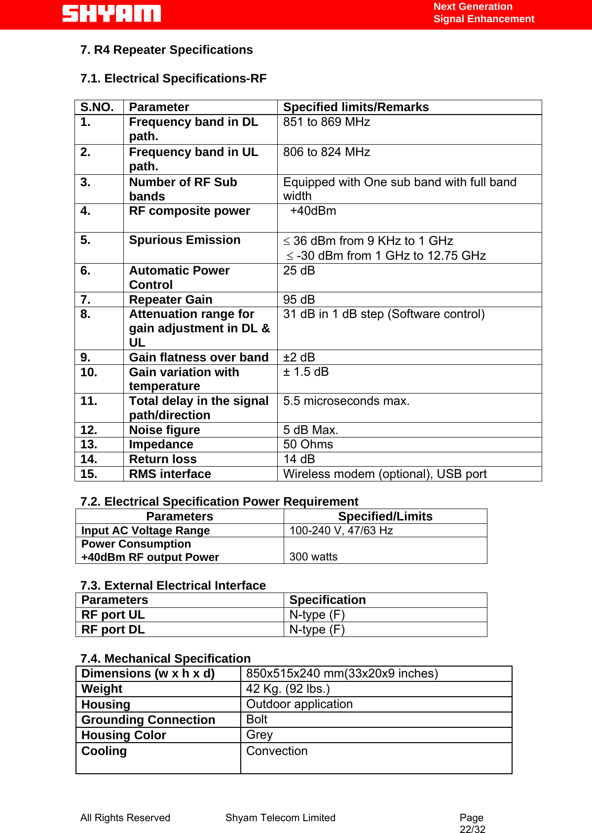
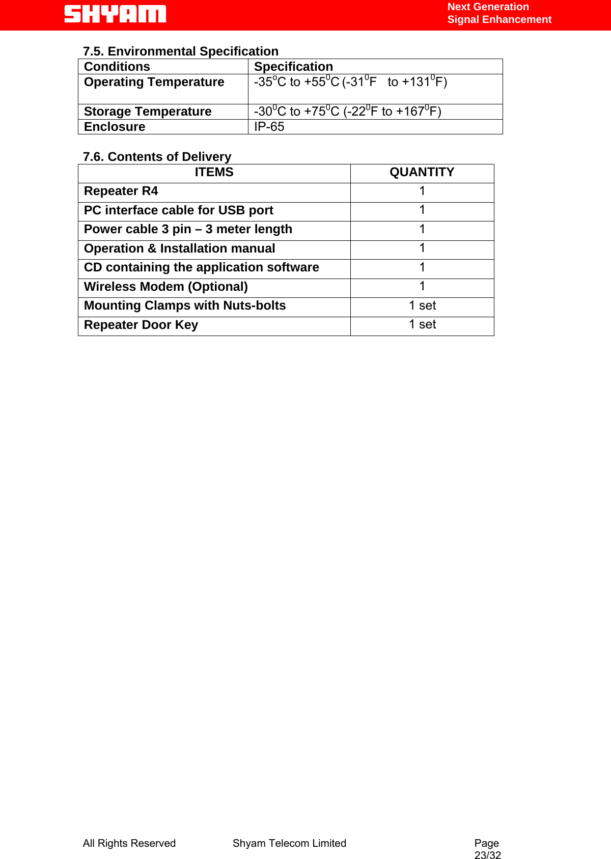
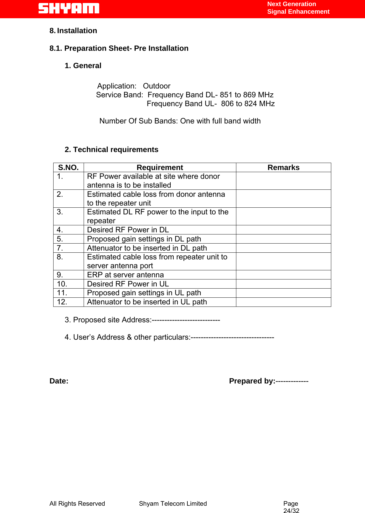
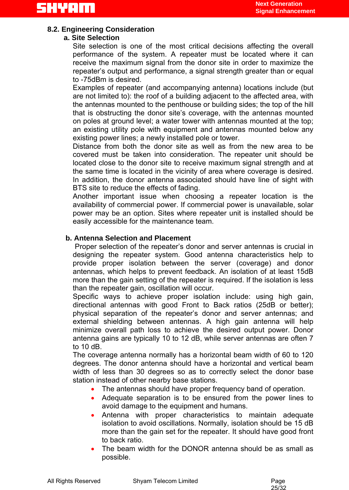
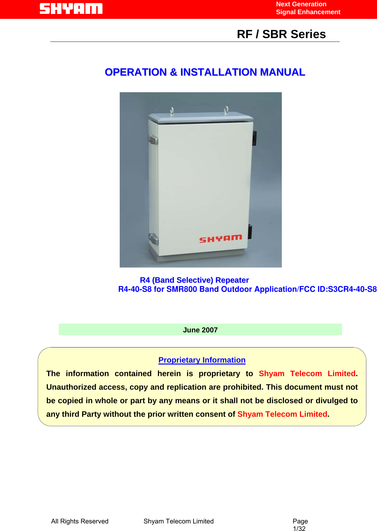
Shyam Telecom R4-40-S8 SMR800 Band Outdoor Repeater R4-40-S8 User Manual User s manual for
Shyam Telecom Inc. SMR800 Band Outdoor Repeater R4-40-S8 User s manual for
UserManual.wiki
>
Shyam Telecom
>
R4 40 S8 User Manual
Manual
Navigation menu
Upload a User Manual
Namespaces
Wiki Guide
HTML
PDF
Info
Views
User Manual
Discussion / Help
Navigation
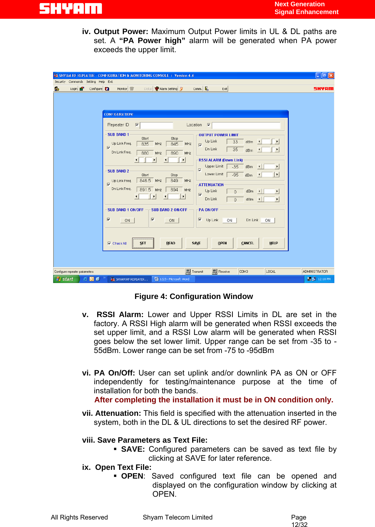
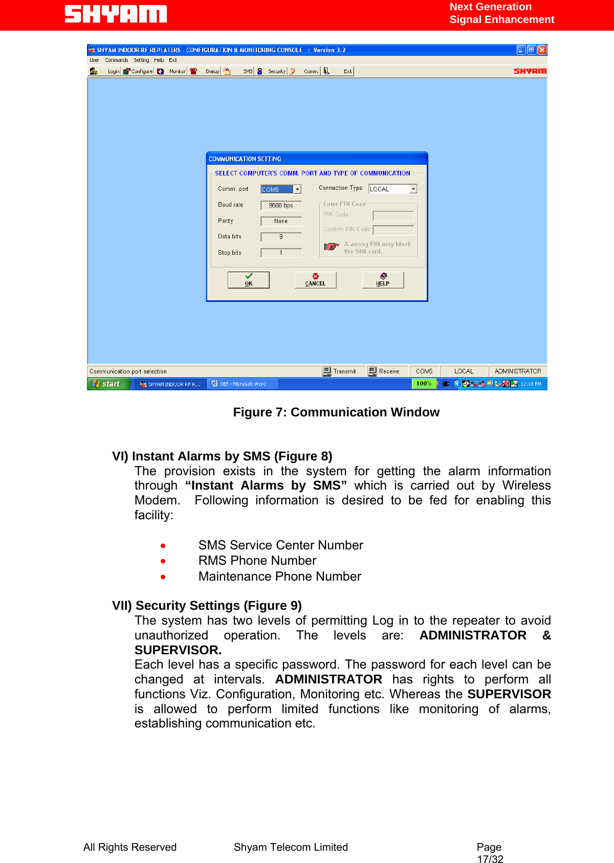
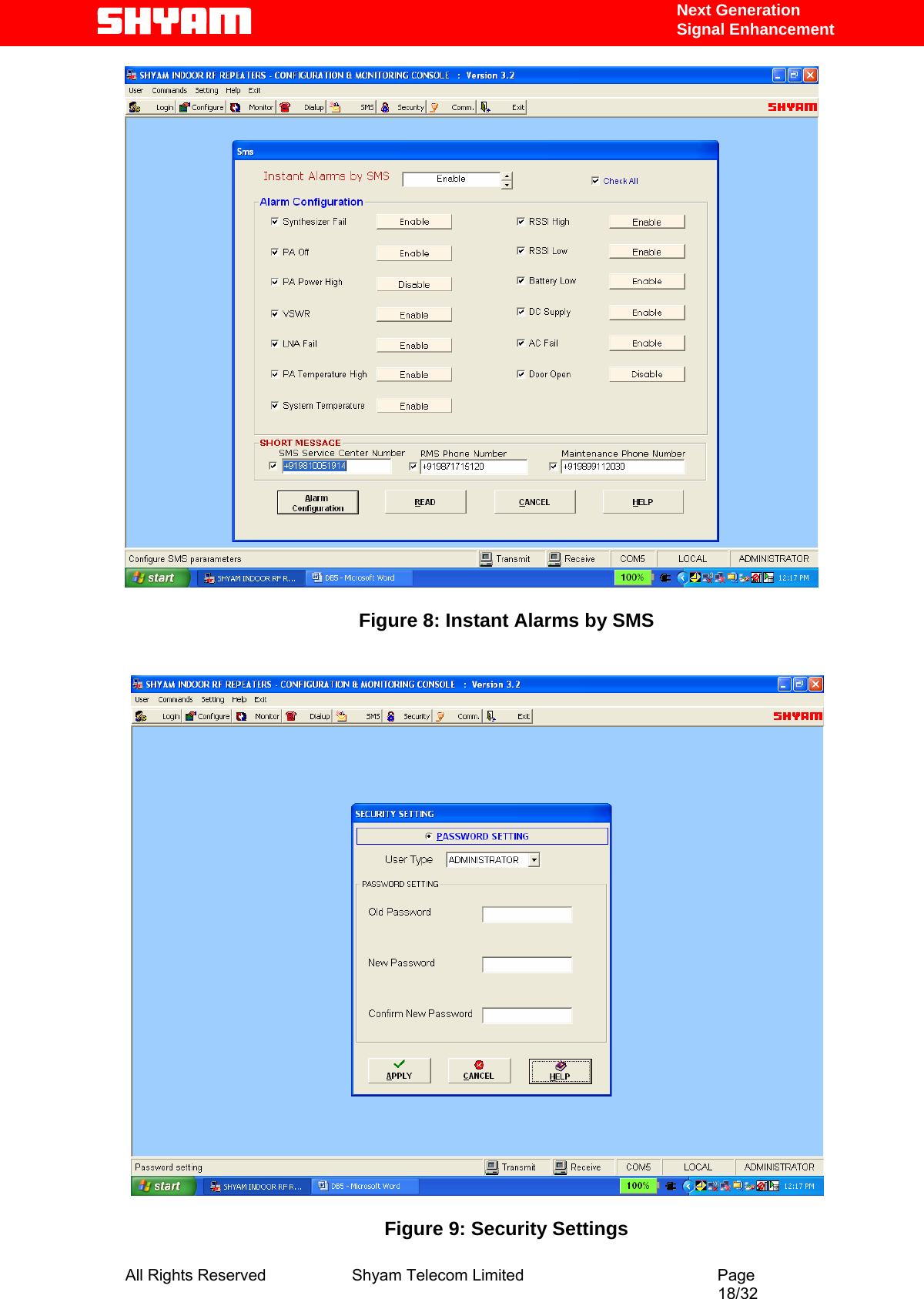
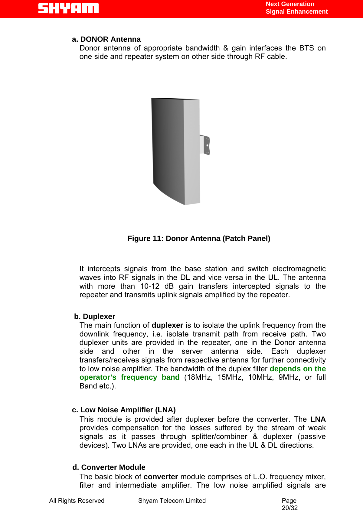
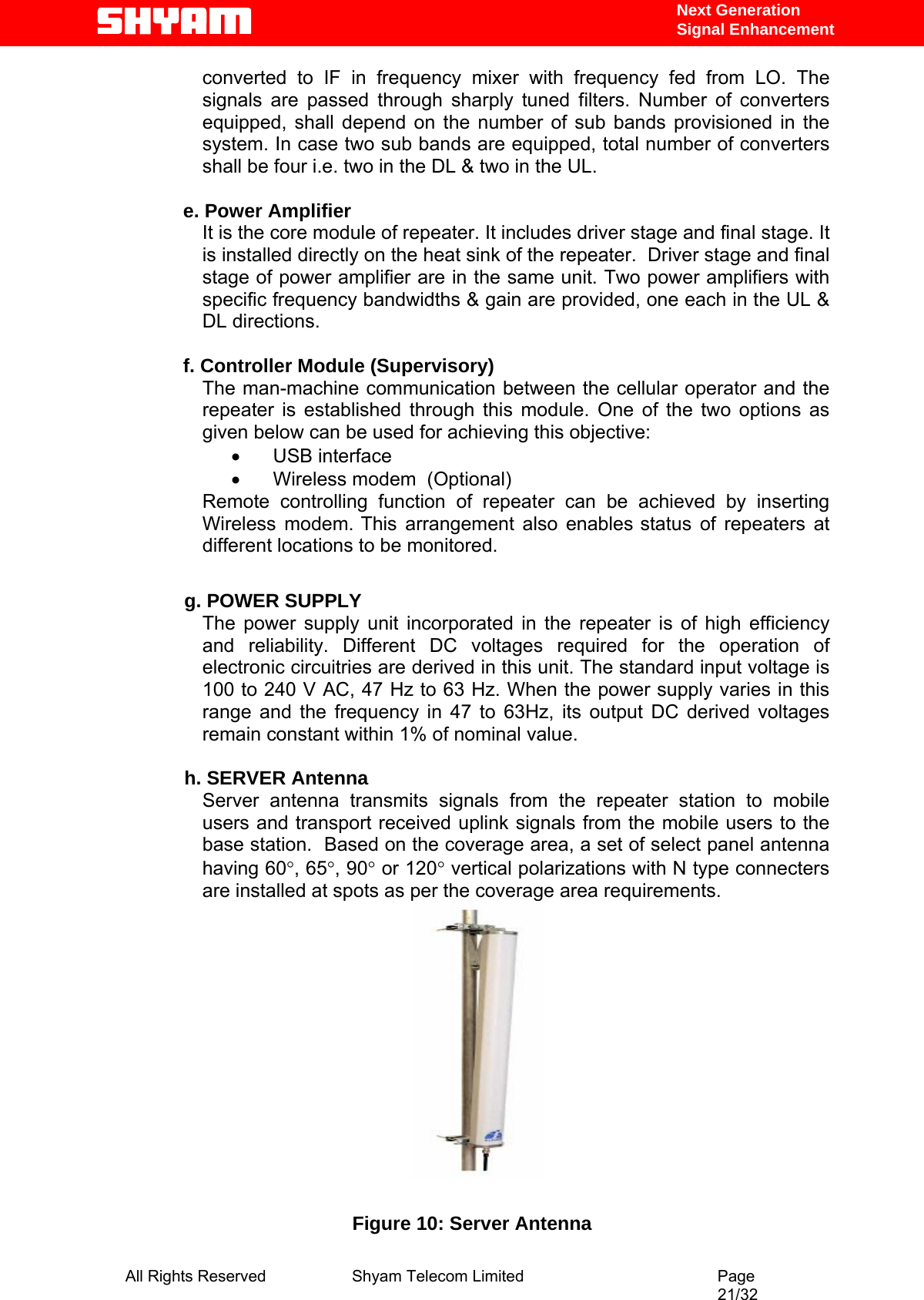
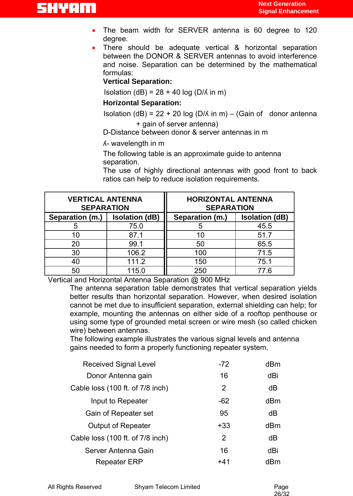
![Next Generation Signal Enhancement 4.4. References [1] ETS 300 086. Radio Equipment and Systems Land mobile service Technical characteristics and test conditions for radio equipment with an internal or external RF connector intended primarily for analogue speech. [2] ETS 300 609-4. Digital cellular telecommunications system (phase 2): Base Station Systems (BSS) equipment specification: Part 4: Repeaters. [3] ETS 300 342-3 Radio Equipment and Systems (RES); Electro-Magnetic Compatibility (EMC) for European Digital Cellular Telecommunications systems. Base Station Radio and ancillary equipment and Repeaters meeting phase 2 GSM requirements. 4.5. General Mobile Communications Systems are planned as cellular systems and each cell of the base station is required to provide RF coverage over a certain geographical area as per defined RF power levels. Due to the RF propagation properties, even using high radiated RF powers or complicated antenna systems, there are zones within the coverage area where the RF signal strength from base station remains inadequate for establishing the desired connectivity to mobile users. Repeaters traditionally are inducted in the Mobile Communication network to fill in the “Dead Zones” caused by blocking of signals by geographic topologies such as mountains, valleys, dense foliage, high rising urban landscapes and other man-made structures. The distance from the base station also adversely affects the RF signal strength. The user views repeaters as a means to extend base station coverage so as to reduce the number of base stations and thereby accelerate network availability. Repeater systems are installed after meticulous planning between BTSs and the mobile users to provide RF coverage in the shadowed regions. Repeater systems are available for different applications and ultimate choice shall depend on some of the factors mentioned below: • Area to be provided with coverage. • Indoor/outdoor coverage. • Availability of BTSs in the vicinity. • Antenna isolation to be achieved. All Rights Reserved Shyam Telecom Limited Page 6/32](https://usermanual.wiki/Shyam-Telecom/R4-40-S8/User-Guide-831188-Page-7.png)
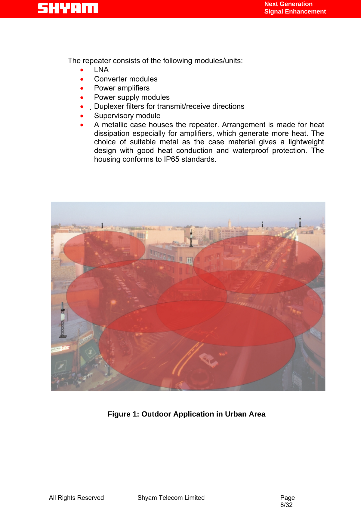
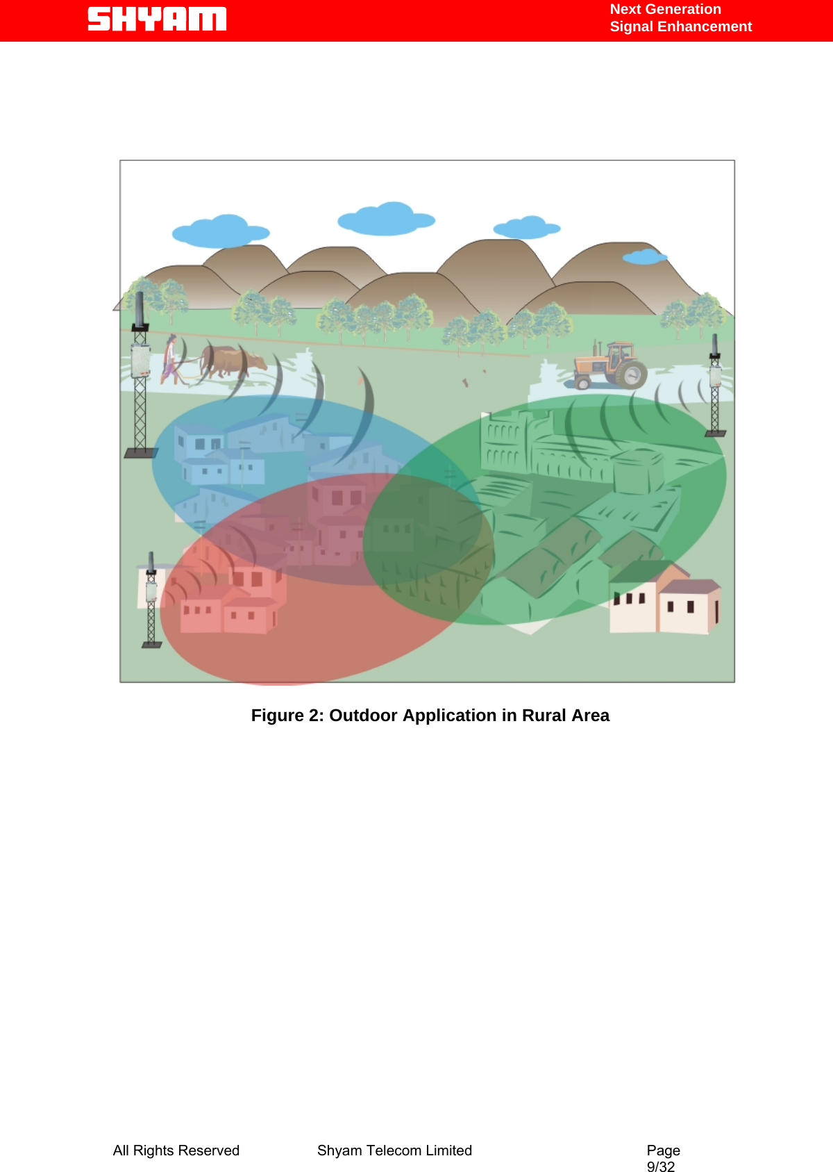
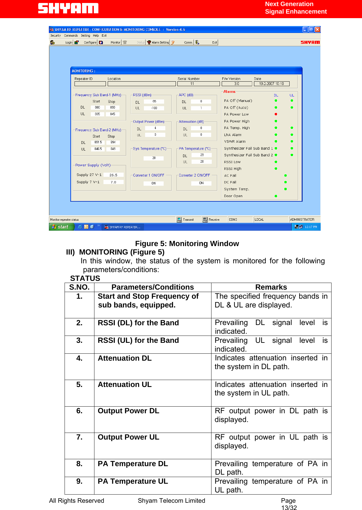
![Next Generation Signal Enhancement 5. Functional Description Of R4 Band Selective Repeater 5.1. General Description The R4 Band Selective Repeater System is designed to provide outdoor coverage and can handle signals up to two sub bands in any one of the service bands, used around the World by various service operators. It provides highly selective amplification in the pre-set band. The details of operating service frequency bands are given below: S.NO. Service Band DL Frequency (MHz) UL Frequency (MHz) 1. SMR 851-869 806-824 2. Cellular 869-894 824-849 3. iDEN 935-941 896-902 4. EGSM 925-960 880-915 5. GSM 900 935-960 890-915 6. DCS 1805-1880 1710-1785 7. PCS 1930-1990 1850-1910 8. UMTS 2110-2170 1920-1980 [The Customer is advised to refer to the packing note giving the details of frequency band set & the bandwidths of different sub bands equipped in the repeater: ony SMR80 Band is subject to this FCC application w/ FCC ID:S3CR4-40-S8] • The repeater adopts duplex mode and bi-directional amplification for U/L & D/L signals between the base station and mobile users. It has been designed for outdoor applications to meet the requirements of large number of users in the targeted area. • It conforms to ETSI standards & safety requirements. • The system can be incorporated with optional Remote Management System (RMS). It enables status monitoring, remote configuration & speedy maintenance. • The system can be customized to meet the requirement of user for coverage by making provision for radiating required RF power in the DL/UL paths to achieve the coverage. The System is incorporated with monitoring facility through USB port with easy GUI interface. • It intercepts signals from the BTS through a DONOR antenna (highly directional outdoor antenna) and distributes the signals to mobile users after amplification through SERVER antennas (omni directional) system in the D/L. • In the U/L, the signals from the mobile users are picked up by SERVER antenna and retransmitted to the BTS after processing & amplification in the repeater. All Rights Reserved Shyam Telecom Limited Page 7/32](https://usermanual.wiki/Shyam-Telecom/R4-40-S8/User-Guide-831188-Page-8.png)