Sicel Technologies DVS-R-100 Dosimetry Verification System User Manual 934 00553 00
Sicel Technologies, Inc. Dosimetry Verification System 934 00553 00
Contents
- 1. Users Manual Part I
- 2. Users Manual Part II
Users Manual Part I

DVS® DOSE VERIFICATION SYSTEM
Operators Manual
Caution: Federal Law restricts the use of this device to sale by or on the order of a physician.
934-00553-00.book Page i Friday, June 16, 2006 8:07 AM

DVS Dose Verification System
ii
© 2006 Sicel Technologies®, Inc. All rights reserved.
Sicel Technologies® is a registered trademark of Sicel Technologies, Inc.
DVS® is a product and registered trademark of Sicel Technologies®, Inc.
Part Number: 934-00553-00 rev. 05
This device complies with Part 15 of the FCC Rules. Operation is subject to the
following two conditions: (1) this device may not cause harmful interference, and
(2) this device must accept any interference received, including interference that
may cause undesired operation.
This product is covered by one or more issued or pending U.S. patents including
one or more of the following:
U.S. Patent Nos. 6,047,214; 6,345,203; 6,263,247; 6,402,689; 6,963,770; 6,963,771;
7,010,340, and 7,011,814.
DVS
DVS-R-100
FCCID TS9-DVS-R-100
934-00553-00.book Page ii Friday, June 16, 2006 8:07 AM

Table of Contents
TABLE OF CONTENTS
1 Welcome . . . . . . . . . . . . . . . . . . . . . . . . . . . . . . . . . . . . . . . . . . . . . . . . . 1
1.1 Product Description . . . . . . . . . . . . . . . . . . . . . . . . . . . . . . . . . . . . . . . . . . .2
1.2 Intended Use . . . . . . . . . . . . . . . . . . . . . . . . . . . . . . . . . . . . . . . . . . . . . . . . .2
1.3 Contraindications, Warnings, Cautions, and Notes . . . . . . . . . . . . . . . . . . .2
Contraindications . . . . . . . . . . . . . . . . . . . . . . . . . . . . . . . . . . . . . . . . . . . .2
Warnings . . . . . . . . . . . . . . . . . . . . . . . . . . . . . . . . . . . . . . . . . . . . . . . . . . .3
Cautions . . . . . . . . . . . . . . . . . . . . . . . . . . . . . . . . . . . . . . . . . . . . . . . . . . . .4
Notes . . . . . . . . . . . . . . . . . . . . . . . . . . . . . . . . . . . . . . . . . . . . . . . . . . . . . .7
1.4 Symbols . . . . . . . . . . . . . . . . . . . . . . . . . . . . . . . . . . . . . . . . . . . . . . . . . . . .7
1.5 Glossary of Terms . . . . . . . . . . . . . . . . . . . . . . . . . . . . . . . . . . . . . . . . . . . . .8
1.6 Statement of Compliance . . . . . . . . . . . . . . . . . . . . . . . . . . . . . . . . . . . . . . .9
Changes or Modifications to the System . . . . . . . . . . . . . . . . . . . . . . . . . .9
1.7 User Equipment Requirements (Not Supplied) . . . . . . . . . . . . . . . . . . . . . .9
2 Dose Verification System Overview . . . . . . . . . . . . . . . . . . . . . . . . . . . 10
2.1 DVS Dosimeter . . . . . . . . . . . . . . . . . . . . . . . . . . . . . . . . . . . . . . . . . . . . . .10
2.2 DVS Reader System . . . . . . . . . . . . . . . . . . . . . . . . . . . . . . . . . . . . . . . . . .11
2.3 DVS Software . . . . . . . . . . . . . . . . . . . . . . . . . . . . . . . . . . . . . . . . . . . . . . .12
2.4 Bar Code Scanner . . . . . . . . . . . . . . . . . . . . . . . . . . . . . . . . . . . . . . . . . . . .13
2.5 DVS Insertion Tool . . . . . . . . . . . . . . . . . . . . . . . . . . . . . . . . . . . . . . . . . . .13
3 Installation and Setup . . . . . . . . . . . . . . . . . . . . . . . . . . . . . . . . . . . . . . 14
3.1 DVS Software Installation Overview . . . . . . . . . . . . . . . . . . . . . . . . . . . . .14
System Requirements . . . . . . . . . . . . . . . . . . . . . . . . . . . . . . . . . . . . . . . .14
Corequisite Software . . . . . . . . . . . . . . . . . . . . . . . . . . . . . . . . . . . . . . . .15
Windows Administrator Login . . . . . . . . . . . . . . . . . . . . . . . . . . . . . . . . .15
3.2 Installing the DVS Plan and Review Software . . . . . . . . . . . . . . . . . . . . . .15
3.3 Installing the DVS Dosimetry Database Server . . . . . . . . . . . . . . . . . . . . .21
3.4 Configuring the DVS Software After Installation . . . . . . . . . . . . . . . . . . .25
Setting up the Database Connection . . . . . . . . . . . . . . . . . . . . . . . . . . . .25
Editing the Admin User . . . . . . . . . . . . . . . . . . . . . . . . . . . . . . . . . . . . . . .27
Entering Institution Information and System Options . . . . . . . . . . . . . .29
3.5 Setting Up the DVS Reader . . . . . . . . . . . . . . . . . . . . . . . . . . . . . . . . . . . . .30
Choose a Location . . . . . . . . . . . . . . . . . . . . . . . . . . . . . . . . . . . . . . . . . . .31
Make the Connections . . . . . . . . . . . . . . . . . . . . . . . . . . . . . . . . . . . . . . . .31
Power on the Reader . . . . . . . . . . . . . . . . . . . . . . . . . . . . . . . . . . . . . . . . .31
Connect to the DVS Dosimetry Database . . . . . . . . . . . . . . . . . . . . . . . . .31
4 Quick Start Instructions . . . . . . . . . . . . . . . . . . . . . . . . . . . . . . . . . . . . 33
4.1 Step 1 - Test Dosimeters . . . . . . . . . . . . . . . . . . . . . . . . . . . . . . . . . . . . . .34
4.2 Step 2 – Implant Dosimeters and Record Implant Information . . . . . . . .34
4.3 Step 3 – Enter Patient Information Into the Plan and Review Software .35
4.4 Step 4 – Measure Radiation Pre-dose and Post-dose Values Using The DVS
Reader . . . . . . . . . . . . . . . . . . . . . . . . . . . . . . . . . . . . . . . . . . . . . . . . . . . .37
934-00553-00.book Page i Friday, June 16, 2006 8:07 AM

DVS Dose Verification System
ii
5 Using the Plan and Review Software . . . . . . . . . . . . . . . . . . . . . . . . . . 38
5.1 Logging into the DVS Plan and Review Software . . . . . . . . . . . . . . . . . . . 38
5.2 DVS Main Menu Overview . . . . . . . . . . . . . . . . . . . . . . . . . . . . . . . . . . . . . 38
5.3 Working With Patient Information . . . . . . . . . . . . . . . . . . . . . . . . . . . . . . 39
Adding, Editing, and Viewing Patients . . . . . . . . . . . . . . . . . . . . . . . . . . 40
Entering Patient, Dosimeter, and Plan Information . . . . . . . . . . . . . . . . 41
Entering Patient and Physician Information . . . . . . . . . . . . . . . . . . . . . . 41
Entering Plans . . . . . . . . . . . . . . . . . . . . . . . . . . . . . . . . . . . . . . . . . . . . . 42
Entering Dosimeters . . . . . . . . . . . . . . . . . . . . . . . . . . . . . . . . . . . . . . . . 43
Changing or Deleting Dosimeters . . . . . . . . . . . . . . . . . . . . . . . . . . . . . . 44
Working with Measurement Fractions and Skipped Fractions . . . . . . . . 45
Deleting a Fraction . . . . . . . . . . . . . . . . . . . . . . . . . . . . . . . . . . . . . . . . . 46
Inserting Skipped Fractions . . . . . . . . . . . . . . . . . . . . . . . . . . . . . . . . . . 46
Changing Information for a Fraction . . . . . . . . . . . . . . . . . . . . . . . . . . . . 47
5.4 Viewing Patient Results . . . . . . . . . . . . . . . . . . . . . . . . . . . . . . . . . . . . . . 48
Displaying a List of Patient Results . . . . . . . . . . . . . . . . . . . . . . . . . . . . 48
Viewing Results Charts . . . . . . . . . . . . . . . . . . . . . . . . . . . . . . . . . . . . . . 49
Viewing Results Reports . . . . . . . . . . . . . . . . . . . . . . . . . . . . . . . . . . . . . 51
5.5 DVS System Administration . . . . . . . . . . . . . . . . . . . . . . . . . . . . . . . . . . . 53
Adding and Editing DVS Users . . . . . . . . . . . . . . . . . . . . . . . . . . . . . . . . . 53
Changing Institutional Information and System Options . . . . . . . . . . . 55
Changing the Database Connections . . . . . . . . . . . . . . . . . . . . . . . . . . . . 56
Backing up and Restoring the DVS Database . . . . . . . . . . . . . . . . . . . . . 57
6 Using the DVS Reader . . . . . . . . . . . . . . . . . . . . . . . . . . . . . . . . . . . . . . 58
6.1 Power On the DVS Reader . . . . . . . . . . . . . . . . . . . . . . . . . . . . . . . . . . . . . 58
6.2 Login to the DVS Reader . . . . . . . . . . . . . . . . . . . . . . . . . . . . . . . . . . . . . . 60
6.3 Test a Dosimeter . . . . . . . . . . . . . . . . . . . . . . . . . . . . . . . . . . . . . . . . . . . . 61
6.4 Scan a Patient . . . . . . . . . . . . . . . . . . . . . . . . . . . . . . . . . . . . . . . . . . . . . . 62
Select a Patient . . . . . . . . . . . . . . . . . . . . . . . . . . . . . . . . . . . . . . . . . . . . 62
Select a Plan/Fraction . . . . . . . . . . . . . . . . . . . . . . . . . . . . . . . . . . . . . . . 63
Take a PRE-Dose Reading . . . . . . . . . . . . . . . . . . . . . . . . . . . . . . . . . . . . 64
Dose the Patient . . . . . . . . . . . . . . . . . . . . . . . . . . . . . . . . . . . . . . . . . . . 66
Take a POST-Dose Reading . . . . . . . . . . . . . . . . . . . . . . . . . . . . . . . . . . . 66
Enter Treatment Notes . . . . . . . . . . . . . . . . . . . . . . . . . . . . . . . . . . . . . . 68
7 Imaging and Therapeutic Compatibility . . . . . . . . . . . . . . . . . . . . . . . . 69
8 Troubleshooting . . . . . . . . . . . . . . . . . . . . . . . . . . . . . . . . . . . . . . . . . . 70
8.1 Troubleshooting the DVS Server System Software Setup . . . . . . . . . . . . 70
8.2 DVS Reader Not Operational . . . . . . . . . . . . . . . . . . . . . . . . . . . . . . . . . . . 70
8.3 Unable to Obtain a Pre-Dose or Post-Dose Reading . . . . . . . . . . . . . . . . 70
8.4 DVS Reader Error Messages . . . . . . . . . . . . . . . . . . . . . . . . . . . . . . . . . . . 70
8.5 Plan and Review Software Error Messages . . . . . . . . . . . . . . . . . . . . . . . 74
9 Maintenance and Technical Support . . . . . . . . . . . . . . . . . . . . . . . . . . . 79
9.1 Dosimeter Maintenance . . . . . . . . . . . . . . . . . . . . . . . . . . . . . . . . . . . . . . 79
9.2 Disinfecting the Reader Wand . . . . . . . . . . . . . . . . . . . . . . . . . . . . . . . . . 79
934-00553-00.book Page ii Friday, June 16, 2006 8:07 AM

DVS Dose Verification System
iii
Table of Contents
9.3 Technical Support . . . . . . . . . . . . . . . . . . . . . . . . . . . . . . . . . . . . . . . . . . . .79
10 Specifications . . . . . . . . . . . . . . . . . . . . . . . . . . . . . . . . . . . . . . . . . . . 80
934-00553-00.book Page iii Friday, June 16, 2006 8:07 AM

DVS Dose Verification System
iv
934-00553-00.book Page iv Friday, June 16, 2006 8:07 AM

Welcome
1WELCOME
The Dose Verification System Operators Manual includes
information about the setup and use of the DVS® (Dose
Verification System). The intended users of this manual are
radiation oncologists, medical physicists, dosimetrists, radiation
therapists, and other personnel that may be assisting in the setup
and use of DVS.
This manual is organized into the following sections:
Section 1 Welcome – provides a brief overview of the product, a
list of indications, contraindications, cautions and warnings, and
summaries of the conventions, symbols and terms used in the
Operators Manual and the device.
Section 2 Dose Verification System Overview – provides a
detailed description of the components of DVS and how it is used.
Section 3 Installation and Setup – provides instructions for
installing and configuring the DVS Software and setting up the
DVS Reader.
Section 4 Quick Start Instructions – provides an overview of the
workflow for testing, implanting, and scanning the DVS
dosimeters.
Section 5 Using the Plan and Review Software – provides the
instructions for using the Plan and Review Software to enter
patient, dosimeter, and plan information and review patient results.
Section 6 Using the DVS Reader – provides the instructions for
using the DVS Reader to test dosimeters and scan patients.
Section 7 Imaging and Therapeutic Compatibility – provides a
chart describing the interactions of an implanted dosimeter with
various imaging and therapeutic modalities.
Section 8 Troubleshooting – provides guidance if you encounter
issues or errors while using DVS.
Section 9 Maintenance and Technical Support – provides
information on maintaining DVS and getting technical support.
Section 10 Specifications – provides the technical specification for
the DVS system.
934-00553-00.book Page 1 Friday, June 16, 2006 8:07 AM

DVS Dose Verification System
2
1.1 Product Description
DVS provides an oncologist with information about the actual
radiation dose delivered to a patient’s tissues and organs, and it
provides charts and statistics for comparing the actual dose to the
prescribed dose. DVS uses an implantable dosimeter and an
external reading system to determine the absorbed dose near a
tumor within a patient. DVS provides the oncologist with dose
information that may be used in conjunction with other clinical
information to make decisions regarding treatment plans or to
identify the need for further investigation.
1.2 Intended Use
DVS is intended for use in radiation therapy to verify treatment
planning and radiation dose to tissue and organs in or near the
irradiated areas of a patient.
1.3 Contraindications, Warnings, Cautions, and Notes
The following section explains the contraindications, warnings,
cautions and notes for DVS.
The terms Warning, Caution, and Note have specific meanings
throughout this manual:
• A Warning advises against actions or situations that could result
in personal injury or death.
• A Caution advises against actions or situations that could
damage equipment or produce inaccurate or invalid data.
• A Note provides useful information regarding the operation or
function of the system.
Contraindications
•DVS may not be used in patients who are already implanted
with other electronic devices such as pacemakers or insulin
pumps. The impact of the potential electronic interference
is unknown.
•Not calibrated for use in electron beam therapy or
brachytherapy. The DVS Dosimeter is pre-calibrated for
external beam photon therapy in the energy range of 6-18 MV
and daily fraction range of 150-250 cGy.
934-00553-00.book Page 2 Friday, June 16, 2006 8:07 AM

DVS Dose Verification System
3
Welcome
• Do not use for patients receiving microwave mediated
therapy.
• Do not use in blood or central nervous system.
• Do not allow patients with a DVS Dosimeter to receive the
following treatments: shortwave diathermy, microwave
diathermy, or therapeutic ultrasound. These could result in
serious injury.
Warnings
• Electric Shock Hazard – Do not remove the covers of the
Reader or Reader Wand assemblies. The DVS Reader and
Reader Wand contain no user serviceable internal parts.
Contact technical support for return information.
• Electric Shock Hazard – The Dose Verification System is
grounded with a three-conductor cable and three-prong
plug. Insert the power cable only into a properly grounded
three-contact outlet.
• Only use the manufacturer-supplied power cord.
• Replace fuse only with same type and rating: 250V 5 AMP,
Type T or 250V 5 AMP, Type 3AG. Failure to replace the
fuse with the same type and rating may pose a fire hazard.
• The DVS system is not suitable for use in the presence of a
flammable anesthetic mixture with air or with oxygen, or
nitrous oxide.
• Be sure that the cables do not pose a trip hazard.
The DVS system is not intended to specify adjustments to
dose.
Dose measurement data obtained using the DVS system
should be used in conjunction with existing planning and
delivery tools to verify delivered dose rather than as a stand
alone tool for determining dose adjustments.
934-00553-00.book Page 3 Friday, June 16, 2006 8:07 AM

DVS Dose Verification System
4
• The Reader Wand is not for use in direct contact with the
patient – especially near wounds. Contact with gowns or
other clothing is acceptable. The Reader Wand is not
intended to be sterile. Disinfect the Reader Wand after
direct skin contact using isopropyl alcohol-based
disinfectants.
• Do not use in a wet environment – could cause
electrocution.
• Only qualified personnel should attempt to implant the
dosimeter.
• The DVS Insertion Tool is extremely sharp. Using medical
imaging, note critical structures in the pre-determined
implant area. Avoid inserting the radiation dosimeter near
critical structures such as veins and arteries.
• Store dosimeters in a cool dry environment.
• Do not use product if there is evidence of sterile packaging
damage, expiration, or contamination of the dosimeter or
insertion tool – inspect for damage or breaches of the
packaging prior to use.
• The dosimeter and insertion tool are single-use devices – do
not attempt to re-use.
• Do not use locking forceps, a hemostat, or a similar locking
instrument to handle the radiation dosimeter; may cause
mechanical damage to the glass.
Cautions
• Proper use of this system depends on careful reading of all
instructions and labels.
• Do not use cellular phones or hand held two-way radios in
close proximity to the DVS Reader.
• Keep CRTs at least 3 feet from the DVS Reader to prevent
the DVS Reader from interfering with the CRT image.
934-00553-00.book Page 4 Friday, June 16, 2006 8:07 AM

DVS Dose Verification System
5
Welcome
• Turn OFF the system power before connecting or
disconnecting any system components or accessories.
Connecting components with power applied may cause
damage to the connectors or connecting circuitry.
• If the dosimeter is tested prior to implantation, (1) do not
remove the dosimeter from its package as this will
compromise sterility and (2) do not place the dosimeters
near metal.
• Do not use a dosimeter near implanted metal objects. Read
range may be compromised.
• Enter the predicted dose in cGy, not monitor units. Entry in
monitor units will cause a false error in the planned vs.
actual dose report.
• The DVS Reader Wand should not be used within 1-2 feet
of large metal objects. Using the Reader Wand close to large
metal objects has the potential to reduce the read range of
the Reader Wand.
• Do not conduct the pre-dose or post-dose reading while the
patient is on a metal table. If the treatment table is metal,
conduct the pre-dose reading before the patient is placed on
the table and the post-dose reading after the patient is
removed from the table. A metal table or other metal
objects will interfere with the functioning of the DVS
Reader Wand.
• Take the post-dose reading within 10 minutes after the end
of therapy. Readings taken beyond 10 minutes decrease
dose accuracy.
• The presence of dosimeters causes MR image artifacts. If an
MRI scan is required in the vicinity of the area in which
dosimeters will be implanted, it is recommended that the
scan be performed prior to dosimeter implantation.
Subsequent imaging of the affected area may require
removal of the dosimeters.
• There are three considerations with regard to implantable
devices and MR imaging: localized heating, movement due
934-00553-00.book Page 5 Friday, June 16, 2006 8:07 AM

DVS Dose Verification System
6
to interaction with the magnetic field, and image distortion
or flare.
Non-clinical testing has demonstrated that the DVS Dosimeter
(device size: 2.1 mm diameter by 20 mm length) is MR
Conditional. It can be scanned safely under the following
conditions:
• Static magnetic field of 1.5 Tesla or less
• Spatial gradient field of 250 Gauss/cm or less
• Maximum whole-body-averaged specific absorption rate
(SAR) of 3.5 W/kg for 15 minutes of scanning
In non-clinical testing, the DVS dosimeter produced a
temperature rise of less than 1.8°C at a maximum whole body
averaged specific absorption rate (SAR) of 3.5 W/kg for 15
minutes of MR scanning in a 1.5 Tesla MR . system: Symphony
Siemens Medical Solutions.
MR image quality may be compromised if the area of interest is
in the exact same area or relatively close to the position of the
DVS dosimeter (following ASTM standard F2119-01 the
largest artifact area in the device long axis: T1 weighted spin
echo, 16.6 cm2; gradient echo, 31.1 cm2). Therefore, it may be
necessary to optimize MR imaging parameters for the presence
of this metallic implant.
It is recommended that where MRI is deemed medically
necessary that MRI be performed prior to implantation of the
dosimeter. Where subsequent MRI is deemed medically
necessary in the vicinity of the dosimeter, the dosimeter may
require removal.
• Do not implant the dosimeter deeper than 12 cm or less
than 3 cm from the surface of the skin. Implanting deeper
than 12 cm may result in the inability of the Reader to
communicate with the implanted dosimeter. Implanting at
least 3 cm deep ensures adequate build-up and minimizes
potential for mechanical damage.
• Do not store dosimeters near stray radiation.
• Implant dosimeters approximately parallel to the long axis
of the body.
934-00553-00.book Page 6 Friday, June 16, 2006 8:07 AM
DVS Dose Verification System
7
Welcome
Notes
The dosimeter is factory calibrated and does not require calibration
during use.
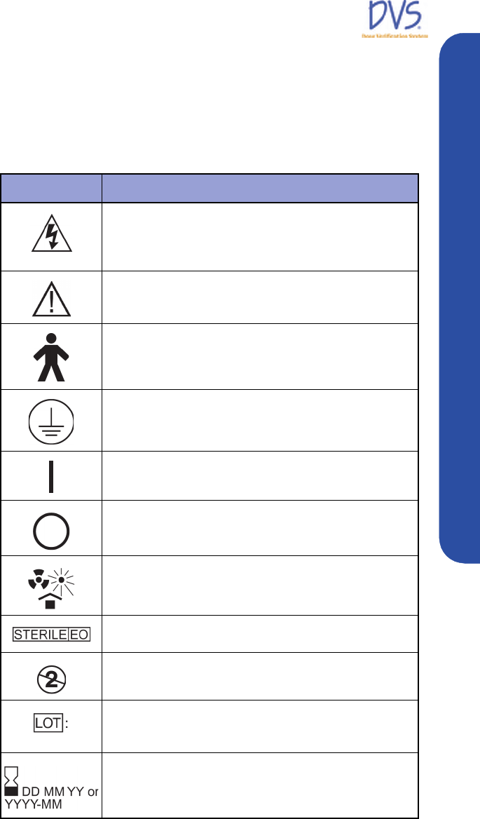
1.4 Symbols
SYMBOL DESCRIPTION
Indicates the Presence of a DANGEROUS VOLTAGE
within the enclosure. This voltage may constitute the risk of
an electric shock if the device is connected to a service
outlet.
Indicates an attention to users to consult accompanying
documents (Operators Manual) for more information on the
device.
Indicates that the Dose Verification System is a Type B
Applied Part.
Protective earth (ground) – Indicates the point where the
safety ground wire connects inside the Reader assembly.
Indicates the ON position of the AC power switch.
Indicates the OFF position of the AC power switch.
Indicates that the parts should be protected from heat and
radioactive sources.
Indicates that the DVS Dosimeter is ethylene-oxide
sterilized.
Indicates the DVS Dosimeter or Insertion Tool is for single
use only.
Indicates the Lot number of the DVS Dosimeter or Insertion
Tool. The ID includes the date of manufacture and a 4-digit
code.
Indicates the sterilization expiration date of the DVS
Dosimeter (DDMMYY) or Insertion Tool (YYYY-MM).
934-00553-00.book Page 7 Friday, June 16, 2006 8:07 AM
DVS Dose Verification System
8
1.5 Glossary of Terms
Base Station – The main part of the DVS Reader, which contains
the touch-screen display for operating the Reader.
cGy – Centi-Gray (hundredths of a Gray (Gy)) unit of radiation
CT – Computed Tomography
Dosimetry Database – The database used by the DVS system for
storing patient, dosimeter, planning, and result information.
Fraction – One radiation treatment session. A treatment plan is
made of one or more fractions.
Isodose Curve – The plot of the radiation dose plan showing lines
of equal radiation dose in cGy.
Insertion Tool – Used for percutaneous and intraoperative implant
procedures.
MRI – Magnetic Resonance Imaging
Plan – A set of fractions where the dose delivered for each fraction
is the same.
Predicted Dose – The dose, in cGy, expected at a dosimeter for a
treatment session.
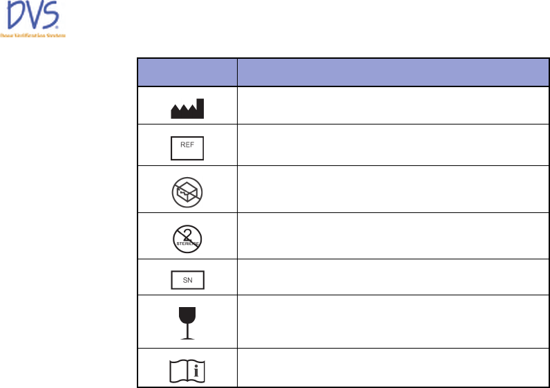
Manufacturer
Catalog Number
Do not use if package is damaged.
Do not re-sterilize
Serial Number
Fragile
Consult Instructions for Use
SYMBOL DESCRIPTION
934-00553-00.book Page 8 Friday, June 16, 2006 8:07 AM

DVS Dose Verification System
9
Welcome
Reader – The DVS Reader system, which is composed of the Base
Station and the Reader Wand.
Reader Wand – The hand-held part of the DVS Reader that
contains the electronics to read the dose measurement from a
dosimeter.
1.6 Statement of Compliance
DVS has been tested and complies with the following safety
standards:
• UL 60601-1
• CSA C22.2 No. 601-M90
• Medical Directive 93/42/EEC
• FCC Part CFR 15
Note: This equipment has been tested and found to comply with
the limits for a Class A digital device, pursuant to Part 15 of the
FCC Rules. These limits are designed to provide reasonable
protection against harmful interference when the equipment is
operated in a commercial environment. This equipment generates,
uses, and can radiate radio frequency energy and, if not installed
and used in accordance with the instruction manual, may cause
harmful interference to radio communications. Operation of this
equipment in a residential area is likely to cause harmful
interference in which case the user will be required to correct the
interference at his own expense.
Changes or Modifications to the System
Changes or modifications to the DVS system not expressly
approved by Sicel Technologies could void the user's authority to
operate the equipment.
1.7 User Equipment Requirements (Not Supplied)
The following equipment and software are required to use DVS:
• Personal Computer with LAN or network access for DVS
Dosimetry Database
• Operating System Requirements:
• Windows XP Pro or later version
934-00553-00.book Page 9 Friday, June 16, 2006 8:07 AM

DVS Dose Verification System
10
2DOSE VERIFICATION SYSTEM OVERVIEW
The Dose Verification System consists of five components:
• DVS Dosimeter
• DVS Insertion Tool
• DVS Reader
• DVS Software (Plan and Review Software and Dosimetry
Database)
• Bar Code Scanner
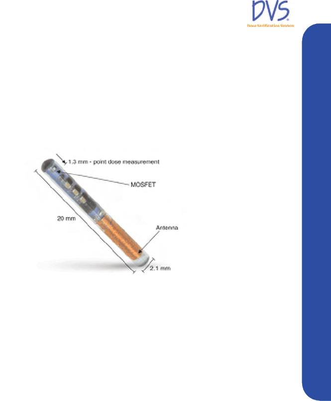
The implantable dosimeter measures in vivo dose from external
beam, photon radiation therapy. The dosimeter uses a
semiconductor device called a MOSFET (metal oxide
semiconductor field effect transistor) to measure radiation.
Radiation within the human therapeutic dose range causes a shift in
the threshold voltage of the MOSFET. By measuring the threshold
voltage before and after radiation dose therapy, the dose fraction
can be calculated. Cumulative dose can be calculated by tabulating
the radiation dose measured at each fraction.
To measure absorbed dose, a pre-dose and post-dose reading must
be taken. The pre-dose reading is taken before the radiation
treatment and the post-dose reading is taken after the radiation
treatment. The pre-dose and post-dose threshold voltage readings
are then used to calculate the daily dose fraction that is reported for
each treatment session. The daily fractional dose values are stored
in the Dosimetry Database and are added together to calculate a
cumulative dose.
The dosimeter is powered by the Reader Wand utilizing
electromagnetic energy and does not contain a battery. The
dosimeter derives all power from the Reader-generated
electromagnetic field. The dosimeter modulates the
electromagnetic field to send the digitized threshold voltage
readings back to the Reader.
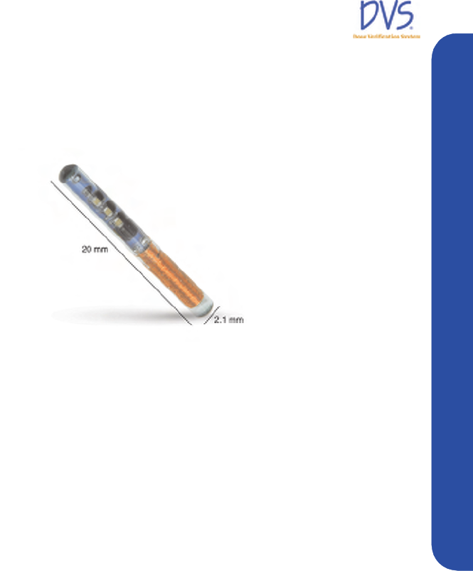
2.1 DVS Dosimeter
The dosimeter is powered telemetrically and measures the radiation
using two MOSFETs. The MOSFETs are hermetically sealed in a
biocompatible glass capsule. The dosimeter is covered by a
polyester surgical mesh for handling, suturing, or fixating the
dosimeter in vivo. The dosimeter is subsequently sterilized with
934-00553-00.book Page 10 Friday, June 16, 2006 8:07 AM
DVS Dose Verification System
11
Dose Verification System Overview
ethylene oxide. In the tissue, the dosimeter provides a radio-opaque
image that registers on a dose planning computed tomography
(CT). The measured dose data can be compared with the prescribed
dose plan.
Figure 1 — DVS Dosimeter
Each dosimeter is factory calibrated by correlating to a NIST-
traceable ion chamber. The calibration information for each
dosimeter is included in a bar code on pre-printed calibration labels.
Dosimeters are provided in sterile packages. The expiration date
printed on the dosimeter package is the date when the dosimeter is
no longer considered sterile. Electrical functionality of the
dosimeter is not affected by the sterility expiration.
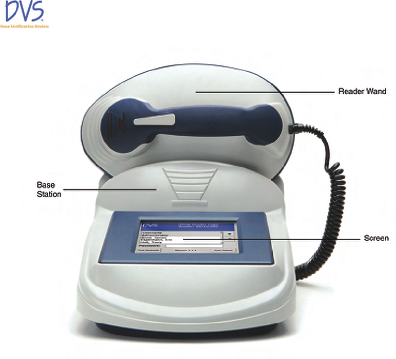
2.2 DVS Reader System
The DVS Reader system is used to take the pre-dose and post-dose
readings from the dosimeter during each treatment session. The
DVS Reader system consists of a Reader Wand and a Base Station
(Figure 2). The Base Station includes a touch screen to view
instructions and enter data. The Reader Wand sits in the cradle of
the Base Station and is removed for reading a patient’s radiation
dose. The highlighted end of the Reader Wand under the LED
indicators is the active reading area.
The DVS Reader can be used on a table top or on a pole mounted to
the wall. The pole should be 1.25” in diameter and able to support
25 pounds.
934-00553-00.book Page 11 Friday, June 16, 2006 8:07 AM
DVS Dose Verification System
12
Figure 2 — DVS Reader
2.3 DVS Software
The DVS Software consists of Plan and Review Software and a
Dosimetry Database. The Plan And Review Software is used to
enter patient treatment information and to access patient data for
viewing and reporting. The Dosimetry Database is a centralized
database to which the Plan and Review Software and the DVS
Reader connect through a local area network (LAN) connection.
All patient information and dosimeter measurements are stored in
the database. A bar code scanner is used to enter calibration
information for the dosimeter. Up to 25 users can simultaneously
access the database.
934-00553-00.book Page 12 Friday, June 16, 2006 8:07 AM
DVS Dose Verification System
13
Dose Verification System Overview
2.4 Bar Code Scanner
The bar code scanner is used to read the dosimeter serial number
and calibration values from a 2D bar code into the Dosimetry
Database. The 2D bar code is packaged with each dosimeter so it is
easy to scan the calibration values into the DVS system. The bar
code scanner does not require any external power.
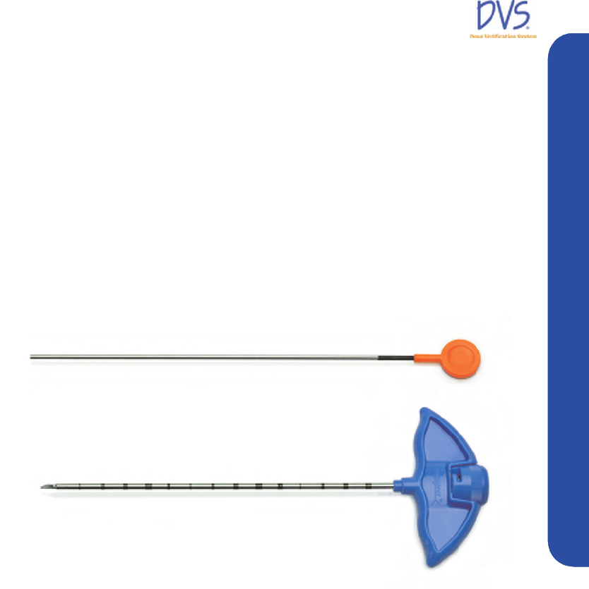
2.5 DVS Insertion Tool
The Insertion Tool is an 11 (eleven) gauge needle similar in design
to a bone biopsy needle. It is used for percutaneous and
intraoperative implant procedures and consists of a cannula, trocar,
and plunger.
Figure 3 — Insertion Tool
934-00553-00.book Page 13 Friday, June 16, 2006 8:07 AM

DVS Dose Verification System
14
3INSTALLATION AND SETUP
The Dose Verification System has three main components that you
need to setup:
• DVS Plan and Review Software
• DVS Dosimetry Database Server
• DVS Reader
This section contains the following steps for installing and setting
up the DVS Software and Reader:
• DVS Software Installation Overview
• Installing the DVS Plan and Review Software
• Installing the DVS Dosimetry Database Server
• Configuring the DVS Software after Installation
• Setting up the DVS Reader
3.1 DVS Software Installation Overview
The DVS Software has two parts: the DVS Plan and Review
Software (client), and the DVS Dosimetry Database (server). You
can install the DVS Dosimetry Database on the same computer as
the Plan and Review Software or you can install it on a separate
computer on a network. For example, you can install the DVS
Dosimetry Database Server on a computer in the server room and
then install the Plan and Review Software on a workstation or
laptop in a central location. You can install the Plan and Review
Software on multiple computers and connect to the one database
server. For administrative purposes, a version of the Plan and
Review Software needs to be installed on the same computer as the
DVS Dosimetry Database Server.
System Requirements
• Plan and Review Software – must be installed on computers
running Windows XP with a minimum of 200 MB of disk
space.
• Dosimetry Database – must be installed on a computer running
Windows XP Pro with a recommended minimum of 5 GB of
disk space. The Windows XP Firewall must be turned off on the
computer where the Dosimetry Database is installed.
934-00553-00.book Page 14 Friday, June 16, 2006 8:07 AM

DVS Dose Verification System
15
Installation and Setup
Corequisite Software
The two parts of the DVS Software each have several corequisite
software components that are installed with the DVS Software:
DVS Plan and Review Software
• Microsoft .NET Framework (.NET)
• Microsoft Data Access Components (MDAC)
DVS Dosimetry Database Server - This uses Microsoft SQL Server.
• Microsoft .NET Framework (.NET)
• Microsoft Data Access Components (MDAC)
• Microsoft SQL Server Desktop Engine (MSDE)
• Microsoft Internet Information Services Web Server (IIS)
• Microsoft SQL Server CE Tools (CE Tools)
Windows Administrator Login
To install the DVS Software, you must be logged into the computer
with Administrator privileges. Check with your system
administrator for instructions on setting up a user ID with
Administrator privileges.
3.2 Installing the DVS Plan and Review Software
The DVS Plan and Review Software is installed on a laptop or
workstation connected to your network. It is the interface for
accessing the patient and dosimeter information stored in the DVS
Dosimetry Database.
To install the DVS Plan and Review Software, perform the
following steps:
1. Place the DVS Software Installation CD into the CD-ROM
drive. The installation program should start automatically. If it
doesn’t, browse to the CD-ROM drive using Windows Explorer
and double-click setup.exe.
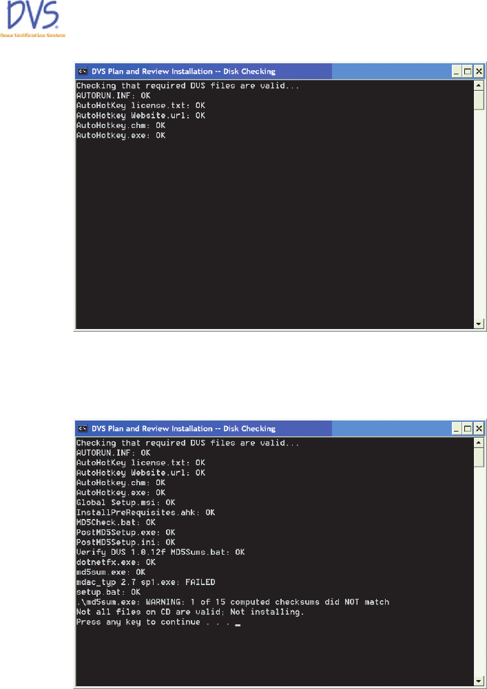
Shortly after inserting the DVS Software Installation CD, a
command window appears. The installation program
automatically verifies the files on the CD-ROM.
934-00553-00.book Page 15 Friday, June 16, 2006 8:07 AM
DVS Dose Verification System
16
Figure 4 — CD File Checking
If the verification process ends with a failure message, press
any key to exit the program, and contact Technical Support.
Figure 5 — CD File Checking Failed
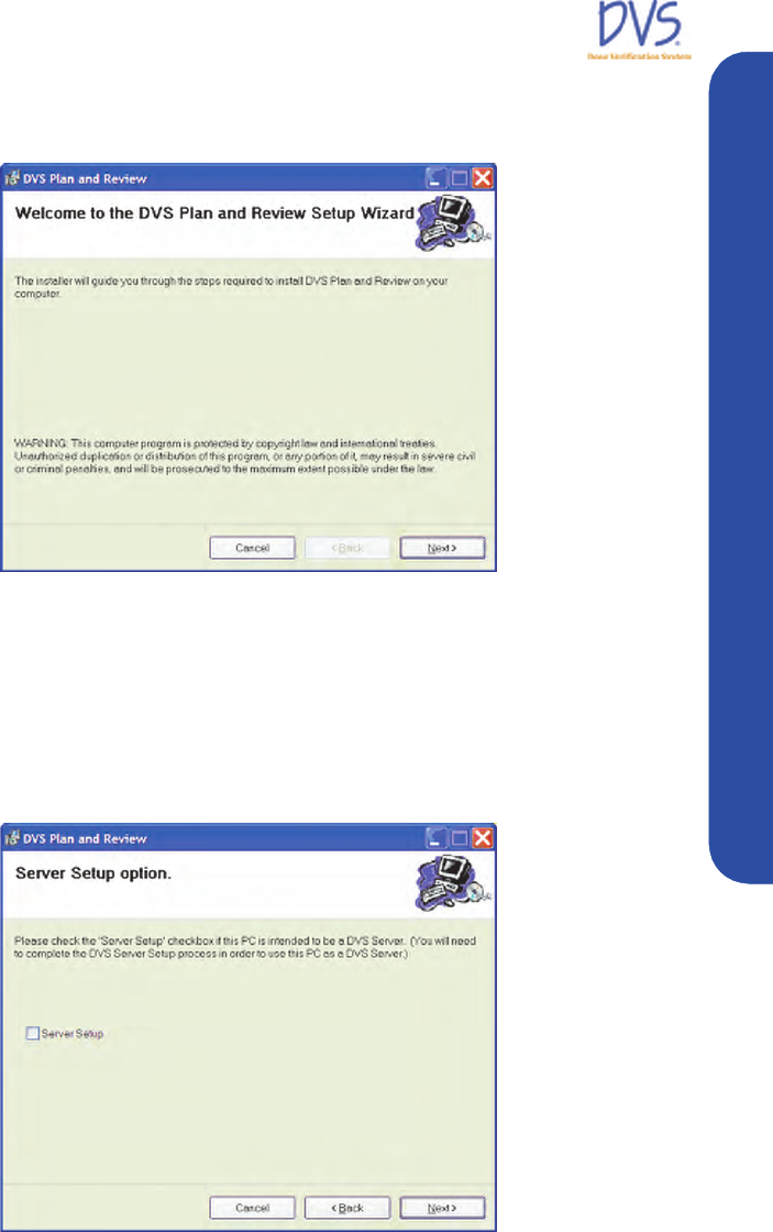
If all files are verified, the DVS Plan and Review Setup
Wizard opens and displays the Welcome panel.
2. On the Welcome panel, click Next. You can click the Next and
Back buttons on the setup wizard to move forward or backward
934-00553-00.book Page 16 Friday, June 16, 2006 8:07 AM
DVS Dose Verification System
17
Installation and Setup
through the setup panels. You can click Cancel to exit the setup
wizard without making any changes to your computer.
Figure 6 — Welcome
3. On the Server Setup Option panel, select the Server Setup
check box if you want to install the DVS Dosimetry Database
on the computer. If selected, the DVS System Server Setup
program installs the database after the Plan and Review
Software installation finishes. If you want to install only the
Plan and Review Software, clear this check box.
Figure 7 — Server Setup Option
934-00553-00.book Page 17 Friday, June 16, 2006 8:07 AM
DVS Dose Verification System
18
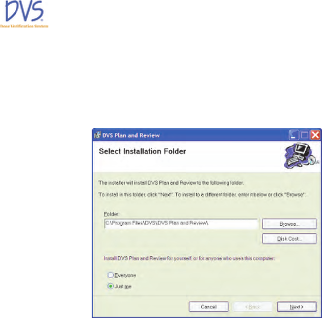
4. Click Next to display the Select Installation Folder panel. By
default, the setup wizard installs the Plan and Review Software
in the C:\Program Files\DVS\DVS Plan and Review folder. To
change the location where the Plan and Review Software is
installed, click Browse to select a new location using the Open
dialog box.
Figure 8 — Select Installation Folder
5. Select Everyone or Just Me to indicate whether everyone who
logs into this computer can use the Plan and Review Software
or just users logged in with the current user ID.
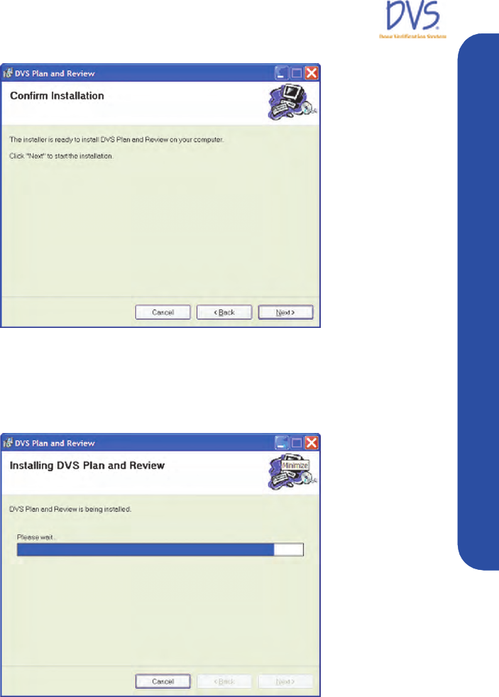
6. Click Next to display the Confirm Installation panel. If you
want to change any of the setup information you entered into
the setup wizard, click Back to change the information.
7. When you are ready to start installing the software, click Next.
934-00553-00.book Page 18 Friday, June 16, 2006 8:07 AM
DVS Dose Verification System
19
Installation and Setup
Figure 9 — Confirm Installation Panel
The next panel that appears displays a progress bar for the
installation program. If you need to stop the installation before it
finishes, click Cancel.
Figure 10 — Installing DVS Plan and Review Software
If the installation program encounters any errors during
installation, the installation is aborted and an error message
appears. If an error occurs, fix the problem and restart the
installation program. The following issues may prevent the
software from installing and result in an error message:
934-00553-00.book Page 19 Friday, June 16, 2006 8:07 AM
DVS Dose Verification System
20
• Low disk space – reinstall the software in a location where
you have enough disk space. The Plan and Review
Software requires at least 200 MB of disk space.
• Inadequate write permissions. – Make sure the user ID you
used to log into the computer has Administrator privileges.
The user ID needs the rights to install applications and
modify the application folders.
• Corrupted files on the installation CD—Contact Technical
Support.
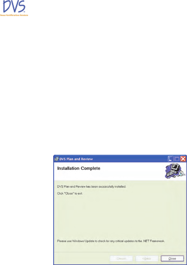
8. When the DVS Plan and Review Software installation finishes,
the Installation Complete panel appears. Click Close to exit
the setup wizard.
If the Server Setup checkbox was selected, the DVS System
Server Setup starts. See section 3.3 Installing the DVS
Dosimetry Database Server on page 21.
Figure 11 — Installation Complete
If you already installed the DVS Dosimetry Database Server or
installed it with the DVS Plan and Review Software, perform the
steps in Configuring the DVS Software after Installation. If the
DVS Dosimetry Database Server has not been setup, see section 3.3
Installing the DVS Dosimetry Database Server on page 21.
934-00553-00.book Page 20 Friday, June 16, 2006 8:07 AM
DVS Dose Verification System
21
Installation and Setup
3.3 Installing the DVS Dosimetry Database Server
The DVS Dosimetry Database stores the client and dosimeter
measurement data. It is accessed using the DVS Plan and Review
Software. Even if you plan to use the Plan and Review Software on
a separate computer, you need to install the Plan and Review
Software on the same computer as the DVS Dosimetry Database
Server.
To install the DVS Dosimetry Database Server and the Dosimetry
Database, perform the following steps:
1. On the computer where you want to install the DVS Dosimetry
Database Server, perform the steps for Installing the DVS Plan
and Review Software on page 15. Be sure to select the Server
Setup check box on the Server Setup Option panel in the
DVS Plan and Review Setup Wizard.
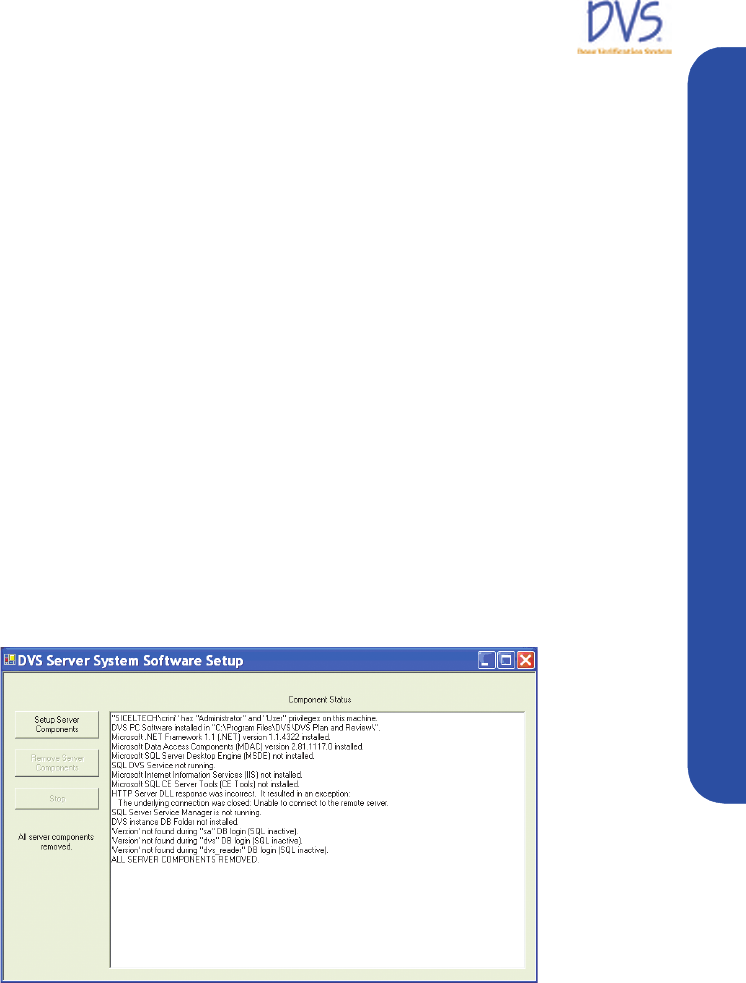
2. When the DVS Plan and Review Setup Wizard completes,
the DVS Server System Software Setup window appears. If
the DVS Server System Software Setup window does not
appear, rerun the installation program and make sure you
selected the Server Setup check box on the Server Setup
Option panel.
Figure 12 — DVS Server System Software Setup
3. Click Setup Server Components. Several windows appear
while SQL Server Desktop Engine installs.
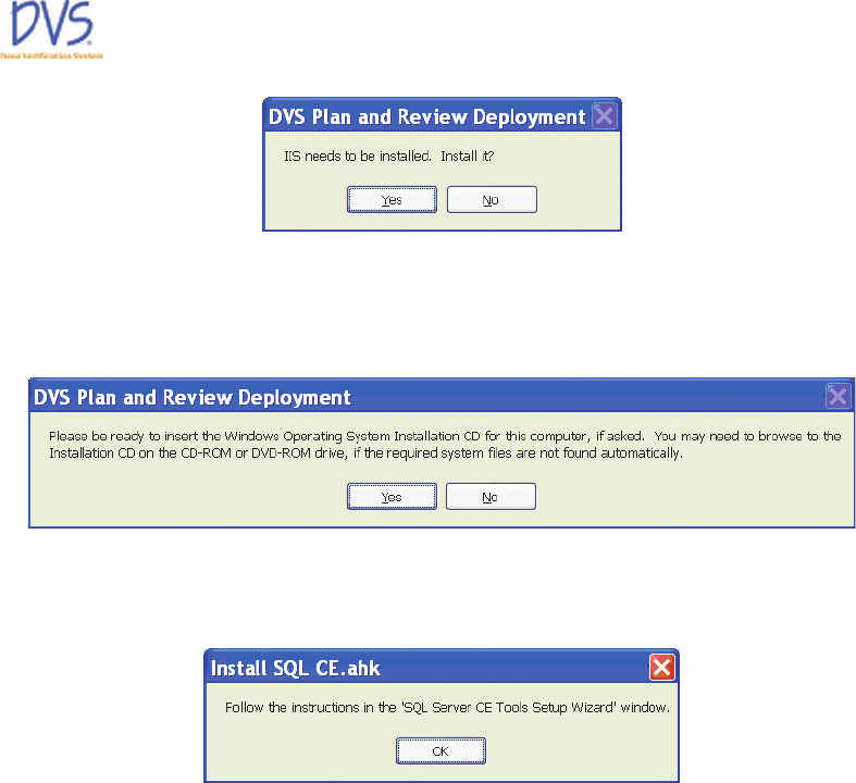
4. If the setup program determines that you need to install
Microsoft Internet Information Services Web Server (IIS), the
following dialog box appears. Click Yes .
934-00553-00.book Page 21 Friday, June 16, 2006 8:07 AM
DVS Dose Verification System
22
5. For the IIS installation, the following dialog box appears to
alert you that the setup program might need system files from
the Windows XP Operating System Installation CD if they are
not found on the computer. Click Yes .
6. When the IIS installation completes, the following dialog box
appears. Click OK to start the SQL Server CE Tools Setup
Wizard.
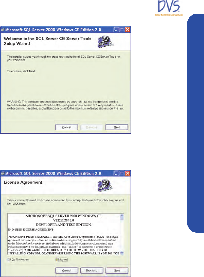
7. Click Next on the first panel of the SQL Server CE Tools
Setup Wizard.
934-00553-00.book Page 22 Friday, June 16, 2006 8:07 AM
DVS Dose Verification System
23
Installation and Setup
Figure 13 — Welcome
8. On the License Agreement panel, select I Agree and click
Next.
Figure 14 — License Agreement Panel
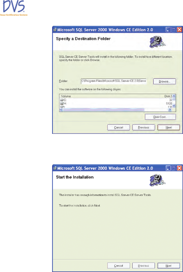
9. On the Specify a Destination Folder panel, click Next.
934-00553-00.book Page 23 Friday, June 16, 2006 8:07 AM
DVS Dose Verification System
24
Figure 15 — Specify a Destination Folder
10. On the Start the Installation panel, click Next.
Figure 16 — Start the Installation
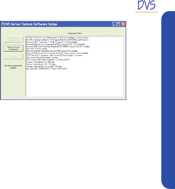
When the SQL Server CE Tools Setup Wizard begins, the
setup program displays a number of windows as it completes
the installation. When the setup program completes, the DVS
Server System Software Setup window displays ALL
SERVER COMPONENTS FULLY INSTALLED in the last
line of Component Status window.
934-00553-00.book Page 24 Friday, June 16, 2006 8:07 AM
DVS Dose Verification System
25
Installation and Setup
Figure 17 — All Server Components Fully Installed
11. Click close (X) to exit the setup program.
3.4 Configuring the DVS Software After Installation
After you have installed the DVS Plan and Review Software and
the DVS Dosimetry Database, you need to configure the DVS
system. Configuration steps include the following:
• Setting up the Database Connection (only required if the Plan
and Review Software is installed on a different computer than
the database server)
• Editing the Admin User
• Entering Institution Information and Preferences
Setting up the Database Connection
If you installed the Plan and Review Software on a different
computer than the DVS Dosimetry Database Server, you must set
up the connection to the database. If the Plan and Review Software
is only installed on the same computer as the DVS Dosimetry
Database Server, skip this section and perform the steps in Editing
the Admin User and Entering Institution Information and
Preferences.
On the computer (or computers) where the Plan and Review
Software is installed without the database server, perform the
following steps:
934-00553-00.book Page 25 Friday, June 16, 2006 8:07 AM
DVS Dose Verification System
26
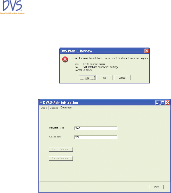
1. Click the DVS Plan and Review icon on the Desktop or select
Start>Programs>DVS>DVS Plan and Review. After a 30
second pause, the following error dialog box appears.
2. Click No. The DVS Administration window appears.
Figure 18 — DVS Administration
3. Click the Database tab.
4. Enter the name of the SQL Server instance with the DVS
Dosimetry Database in the Database Server field. For
example:
<servername>
\DVS
By default, the Database Server field is set to .\DVS which
indicates that the DVS Database is installed locally on the same
computer as the Plan and Review Software.
5. Click Done. The DVS Login dialog box appears.
934-00553-00.book Page 26 Friday, June 16, 2006 8:07 AM
DVS Dose Verification System
27
Installation and Setup
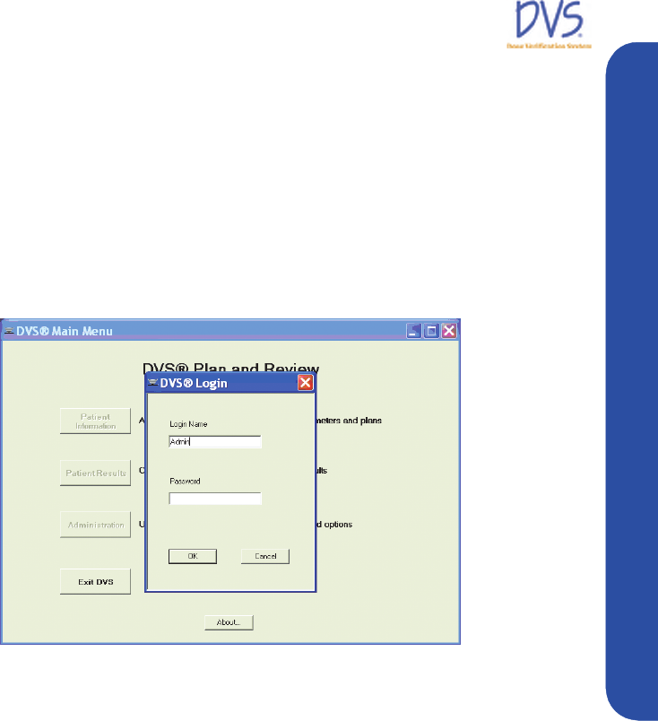
Editing the Admin User
By default, an Admin login name with no password is setup in the
DVS system so that you can login to the DVS Software initially.
After installation, you should login using the Admin login and set
the Admin user password, user information, and authorizations.
To edit the Admin user, perform the following steps:
1. Click the DVS Plan and Review icon on the Desktop or select
Start>Programs>DVS>DVS Plan and Review. The DVS
Main Menu and DVS Login dialog box appears.
Figure 19 — DVS Login
2. In the Login field, enter Admin (case sensitive) and leave the
Password field blank.
3. Click OK. The DVS Main Menu for the DVS Plan and
Review Software appears.
934-00553-00.book Page 27 Friday, June 16, 2006 8:07 AM
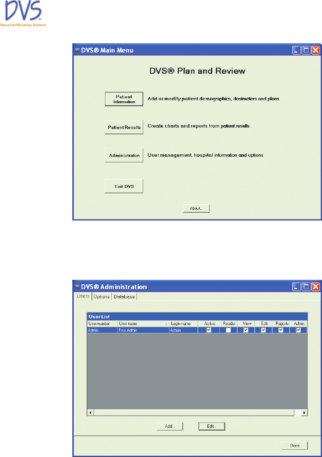
DVS Dose Verification System
28
Figure 20 — DVS Main Menu
4. Click Administration to display the DVS Administration
window.
Figure 21 — DVS Administration
5. Click the Users tab.
6. Select the Admin user from the User List and click Edit.
934-00553-00.book Page 28 Friday, June 16, 2006 8:07 AM
DVS Dose Verification System
29
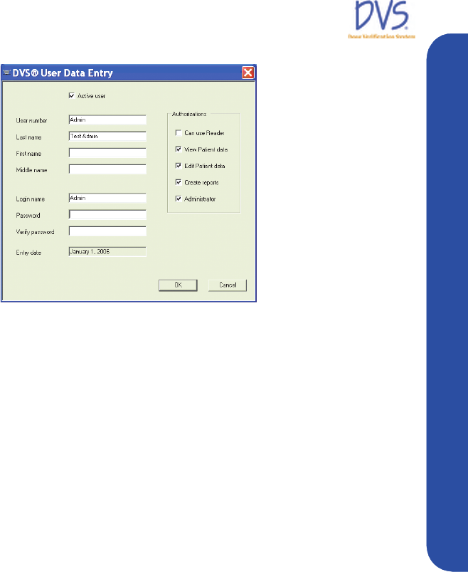
Installation and Setup
Figure 22 — User Data Entry
7. In the User Data Entry dialog box, edit the user information,
password, and authorizations.
• Password - must be numeric (0-9) and at least 4 digits long.
Be sure to set a secure password for the default Admin user.
• Authorizations – select the tasks you want the user to be
able to perform. The Admin user should only have
Administrator authorization. Administrator authorizations
let the user access the Administration dialog box.
8. When you are finished editing the user, click OK to close the
dialog box and return to the Users tab.
9. Click Done.
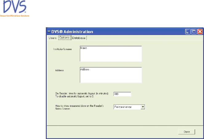
Entering Institution Information and System Options
To enter institution information and set the options for DVS,
perform the following steps:
1. Click the DVS Plan and Review icon on the Desktop or select
Start>Programs>DVS>DVS Plan and Review. The DVS
Main Menu and DVS Login dialog box appears.
2. In the DVS Login dialog box, enter the Admin login name and
password.
3. Click OK. The DVS Main Menu for the DVS Plan and
Review Software appears.
4. Click Administration.
5. Click the Options tab.
934-00553-00.book Page 29 Friday, June 16, 2006 8:07 AM
DVS Dose Verification System
30
Figure 23 — Options
6. Enter the Institution Name and Address.
7. Enter the time in minutes after which you want the DVS Reader
to automatically logout. To disable automatic logout, set the
value to 0 (zero).
8. Select how you want to display measured doses on the DVS
Reader Notes screen:
• None
• Percent Error
• Absolute Dose
9. Click Done when finished.
3.5 Setting Up the DVS Reader
To set up the DVS reader perform the following steps:
• Choose a Location
• Make the Connections
• Power on the Reader
• Connect to the DVS Dosimetry Database
934-00553-00.book Page 30 Friday, June 16, 2006 8:07 AM

DVS Dose Verification System
31
Installation and Setup
Choose a Location
Find a location for the DVS Reader in or near the treatment room.
The DVS Reader can be placed on a counter top or attached to a
pole mounted to the wall. The pole should be 1.25” in diameter and
able to support 25 pounds.
Choose a place that is:
• Near an electrical outlet
• Near a local area network (LAN) connection
•Not in the radiation path of the linear accelerator
Make the Connections
There are three connections that you must make:
• Reader Wand - Connect the Reader Wand cable to the back of
the Reader Base Station. Turn the connector 1/4-turn to lock it
in place.
• Ethernet Cable - Connect the Ethernet cable to the back of the
base station and then to a LAN connection in the room.
• Power cord - Connect the power cord to the back of the base
station and then to the wall outlet.
Note: The USB connection on the back of the Base Station is for
field service.
Power on the Reader
To power on the Reader, use the switch on the back of the base
station near the power cord.
Connect to the DVS Dosimetry Database
After powering on the reader, you need to setup the connection to
the DVS Dosimetry Database.
1. Contact Sicel Technical Support, and get the Administrator
password-of-the-day.
2. Power on the DVS Reader. The Power On screen appears
briefly.
934-00553-00.book Page 31 Friday, June 16, 2006 8:07 AM
DVS Dose Verification System
32
Figure 24 — Power On
3. On the Initializing DVS Reader screen, press Login as
Administrator.
Figure 25 — Initializing DVS Reader
4. Select the Administrator user in the users list.
5. Enter the password-of-the-day received from Technical
Support.
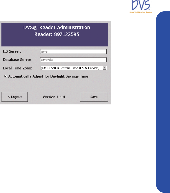
6. On the Reader Administrator screen, enter the name of the
server computer in the IIS Server field. This is typically the
same as the name of the server entered in the Database Server
field, but without the \DVS instance name.
934-00553-00.book Page 32 Friday, June 16, 2006 8:07 AM
DVS Dose Verification System
33
Quick Start Instructions
Figure 26 — Administration
7. In the Database Server field, enter the server name and SQL
server instance . For example:
<server>\DVS
where <server> is the name of the database server computer.
8. Select the local time zone from the drop-down list box.
9. (Optional) Select the Automatically Adjust for Daylight
Saving Time check box. The date and time is automatically set
when the DVS Reader connects to the DVS Dosimetry
Database Server.
10. Press Save.
11. Wait for the Initializing DVS Reader screen to appear and
then turn off the power to the DVS Reader.
12. Power on the DVS Reader.
4QUICK START INSTRUCTIONS
This section provides an overview of the workflow for using the
DVS system:
• Step 1 – Test Dosimeters (optional)
• Step 2 – Implant Dosimeter and Record Implant Information
• Step 3 – Enter Patient Information into the Plan and Review
Software
934-00553-00.book Page 33 Friday, June 16, 2006 8:07 AM

DVS Dose Verification System
34
• Step 4 – Measure Radiation Pre-Dose and Post-Dose Values
Using the DVS Reader
4.1 Step 1 - Test Dosimeters
Using the DVS Reader, you can test dosimeters before sending
them to surgery. This assures that the dosimeters are working
properly. This step is encouraged but not required.
Important: Do not remove the dosimeters from the package
because this will compromise sterility. Dosimeters can be scanned
through the package. Check the expiration date on the outer
package to ensure sterility.
1. Login to the DVS Reader.
2. Press Test Dosimeter on the Reader Login screen.
3. Hold the Reader Wand near the dosimeter.
4. Press the button on the Reader Wand to scan the dosimeter.
Below the status bar, the DVS Reader displays one of the
following messages:
• Dosimeter <number> was found – the dosimeter is
functional
• No Dosimeter found – the dosimeter could not be read
5. Press Logout to exit.
4.2 Step 2 – Implant Dosimeters and Record Implant Information
Verify that the DVS Dosimeter and insertion tool package sterility
have not been compromised, are not expired, and that the items
have not been contaminated prior to implantation.
At surgery, specify the implant location of each dosimeter on the
transfer labels provided. The transfer label information aids the
dosimetrist in identifying the dosimeters on a CT scan. For each
dosimeter, retain one transfer label in the surgical records and
return the other to Radiation Oncology.
934-00553-00.book Page 34 Friday, June 16, 2006 8:07 AM
DVS Dose Verification System
35
Quick Start Instructions
4.3 Step 3 – Enter Patient Information Into the Plan and Review Software
Using the Plan and Review Software, enter the patient’s
demographic information and dose planning information. Ensure
that the predicted dose at the dosimeter was obtained by measuring
the point dose 1.3 mm from the end of the capsule opposite the
antenna (Figure 27). Use a CT scout film or radiograph to
determine dosimeter orientation within the patient (Figure 28).
Figure 27 — DVS Dosimeter Sensitive Volume
934-00553-00.book Page 35 Friday, June 16, 2006 8:07 AM