Sicel Technologies DVS-R-200 Low Frequency RFID User Manual Installation Manual
Sicel Technologies, Inc. Low Frequency RFID Installation Manual
UserManual.wiki
>
Sicel Technologies
>
DVS-R-200 User Manual
>
Installation Manual
Contents
1.
Installation Manual
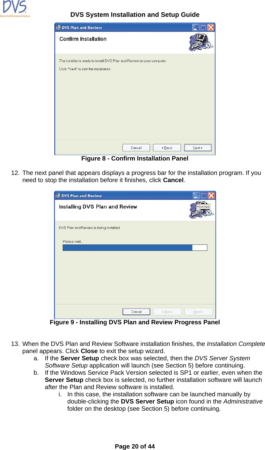
2.
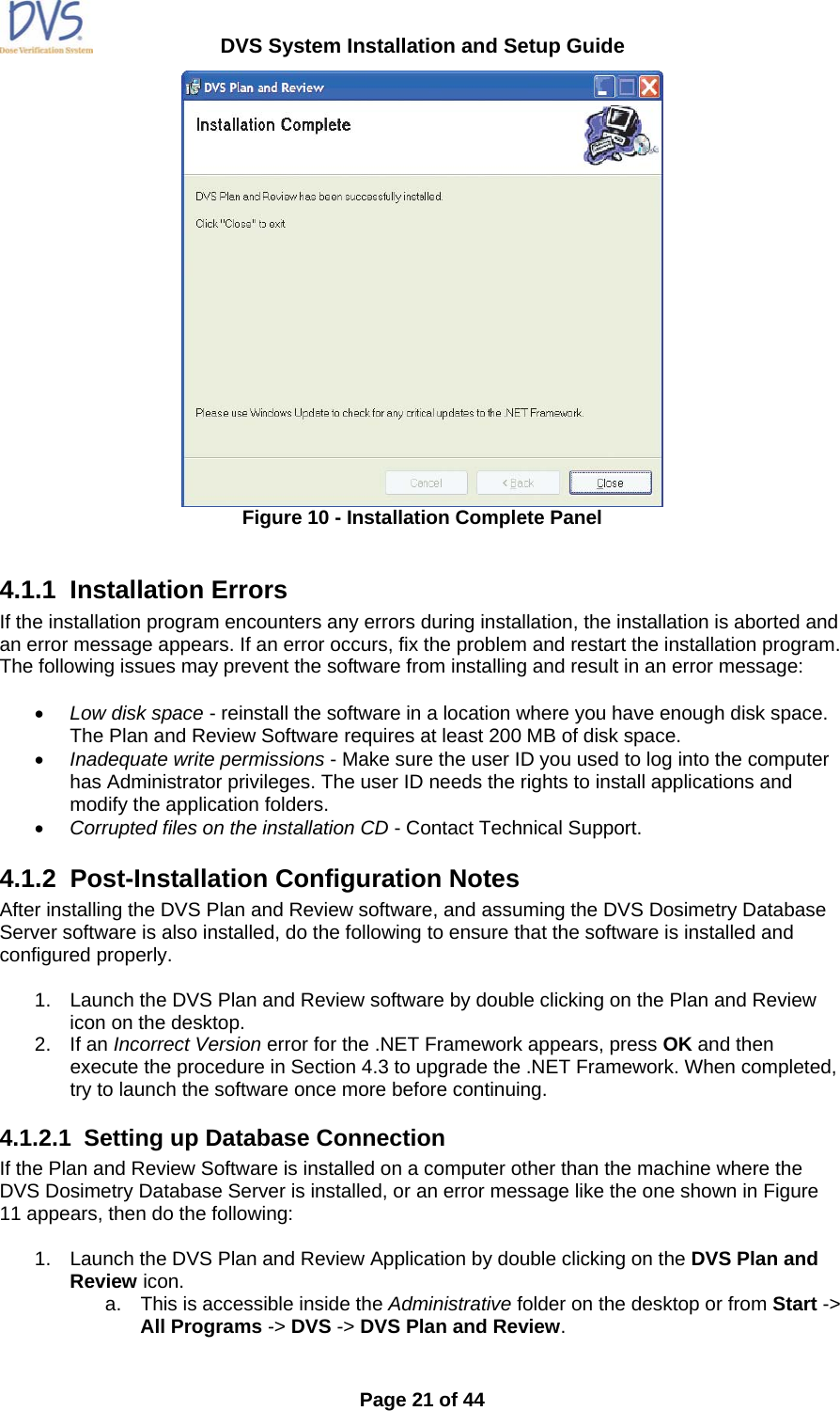
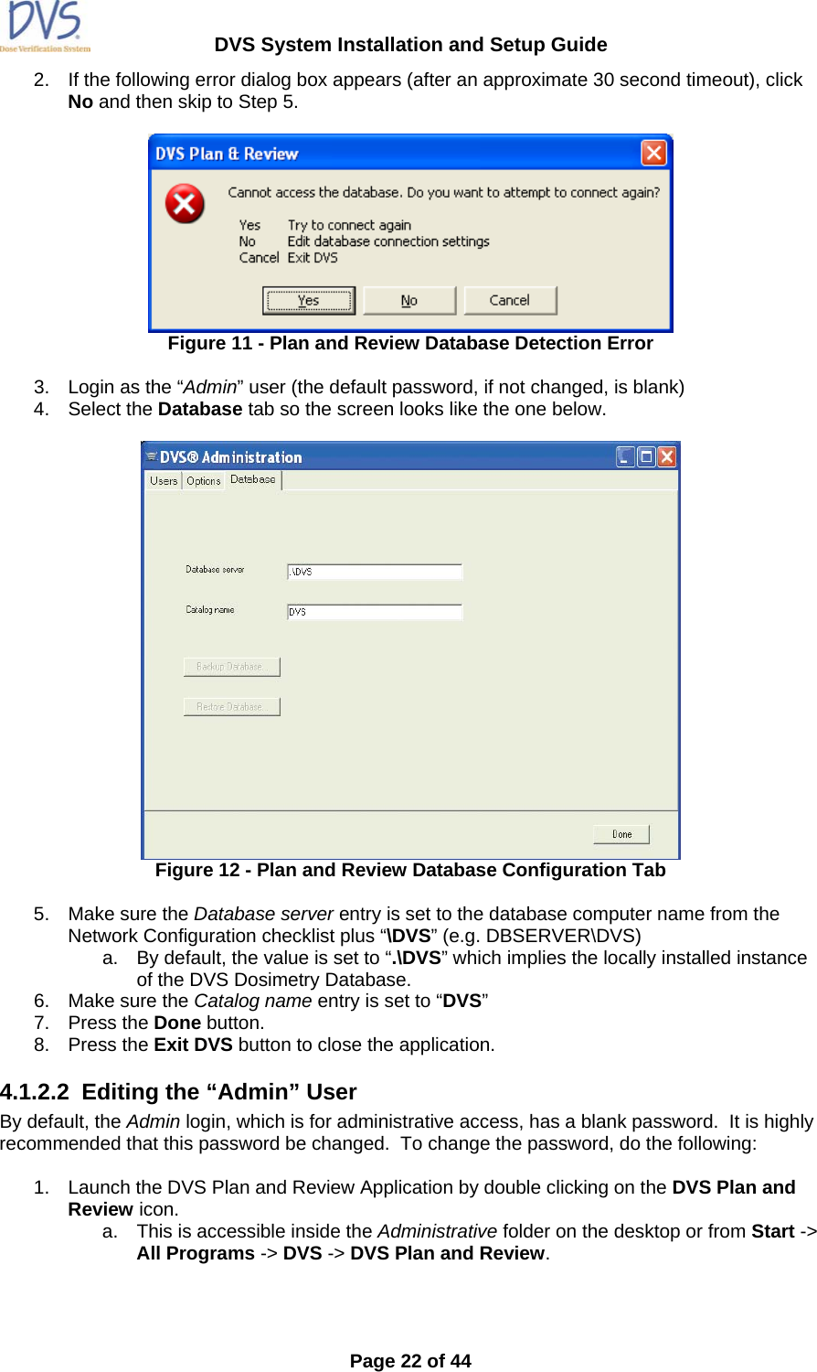
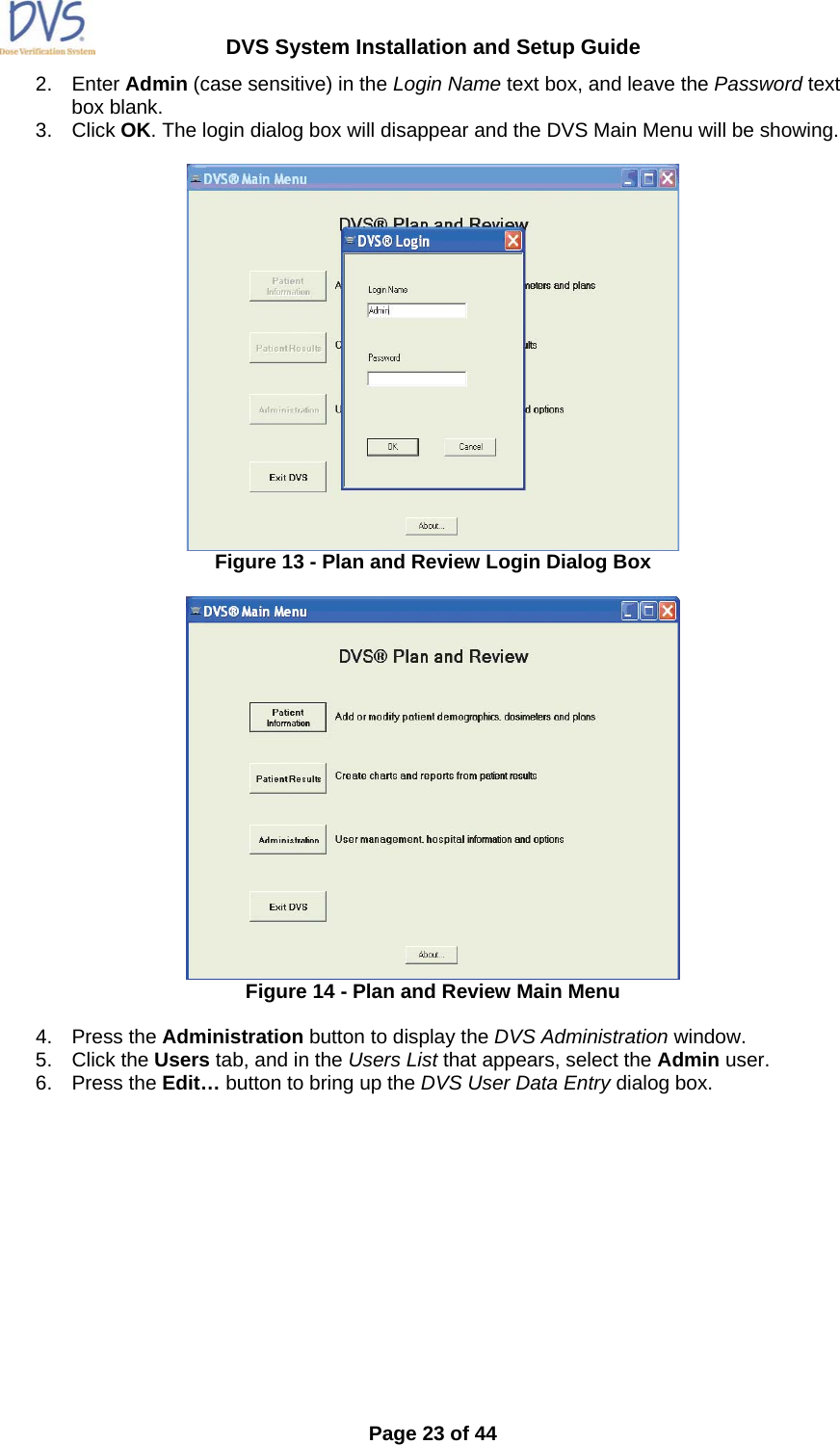
User Manual
Installation Manual
Navigation menu
Upload a User Manual
Namespaces
Wiki Guide
HTML
PDF
Info
Views
User Manual
Discussion / Help
Navigation

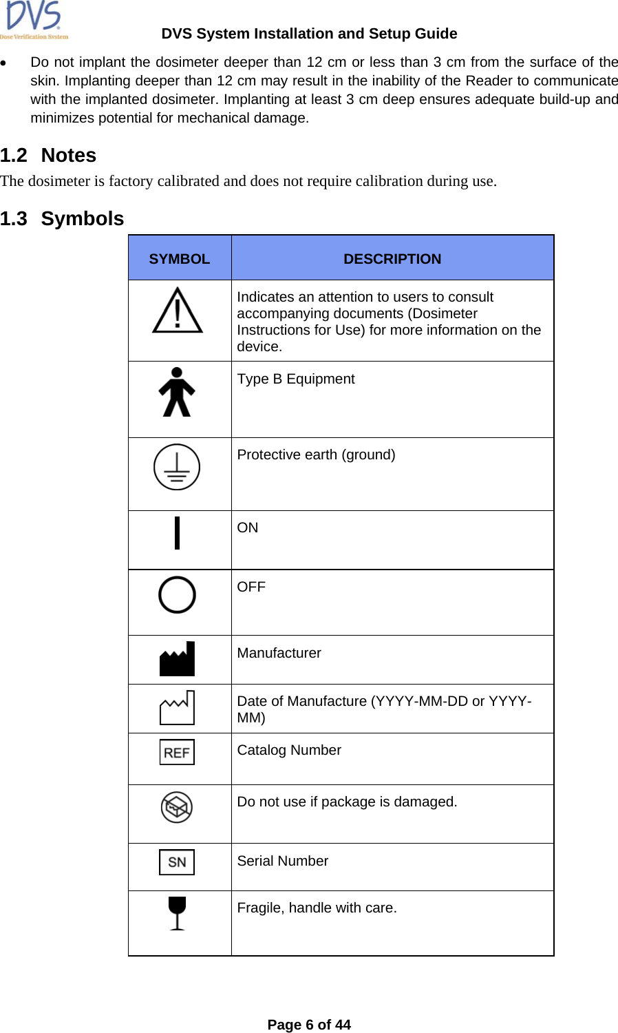
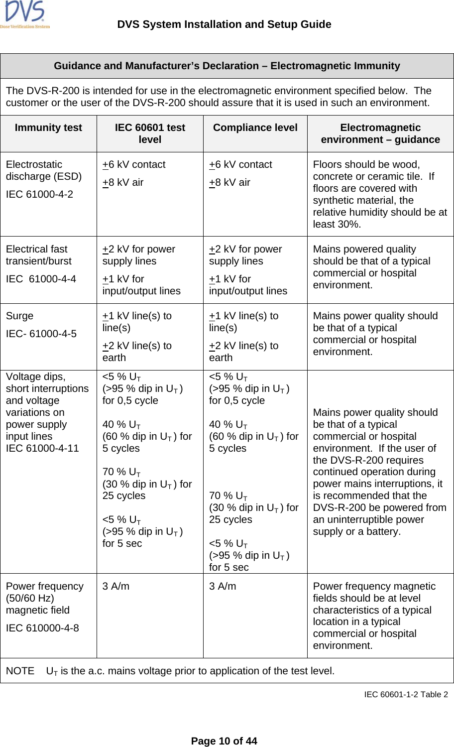
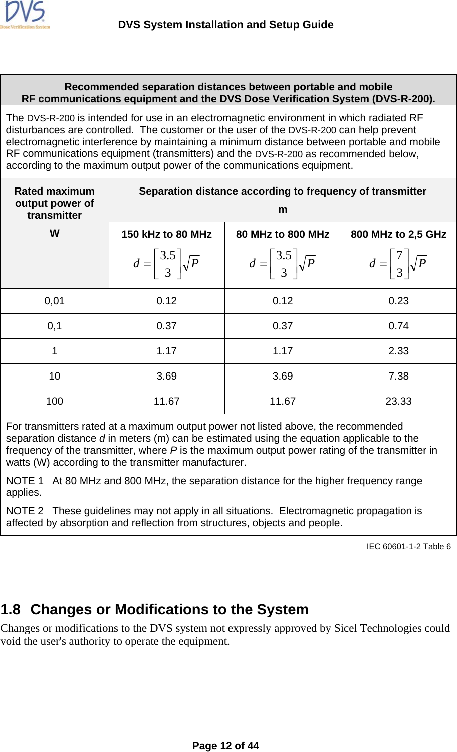
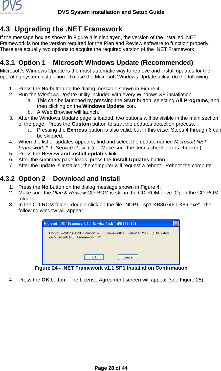
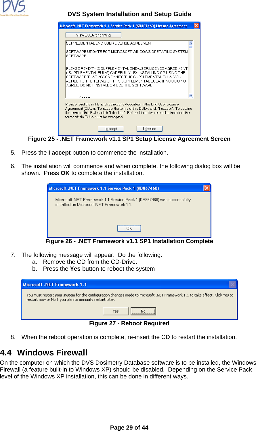
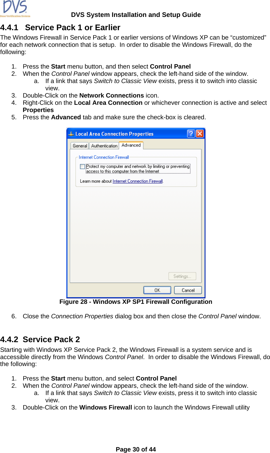
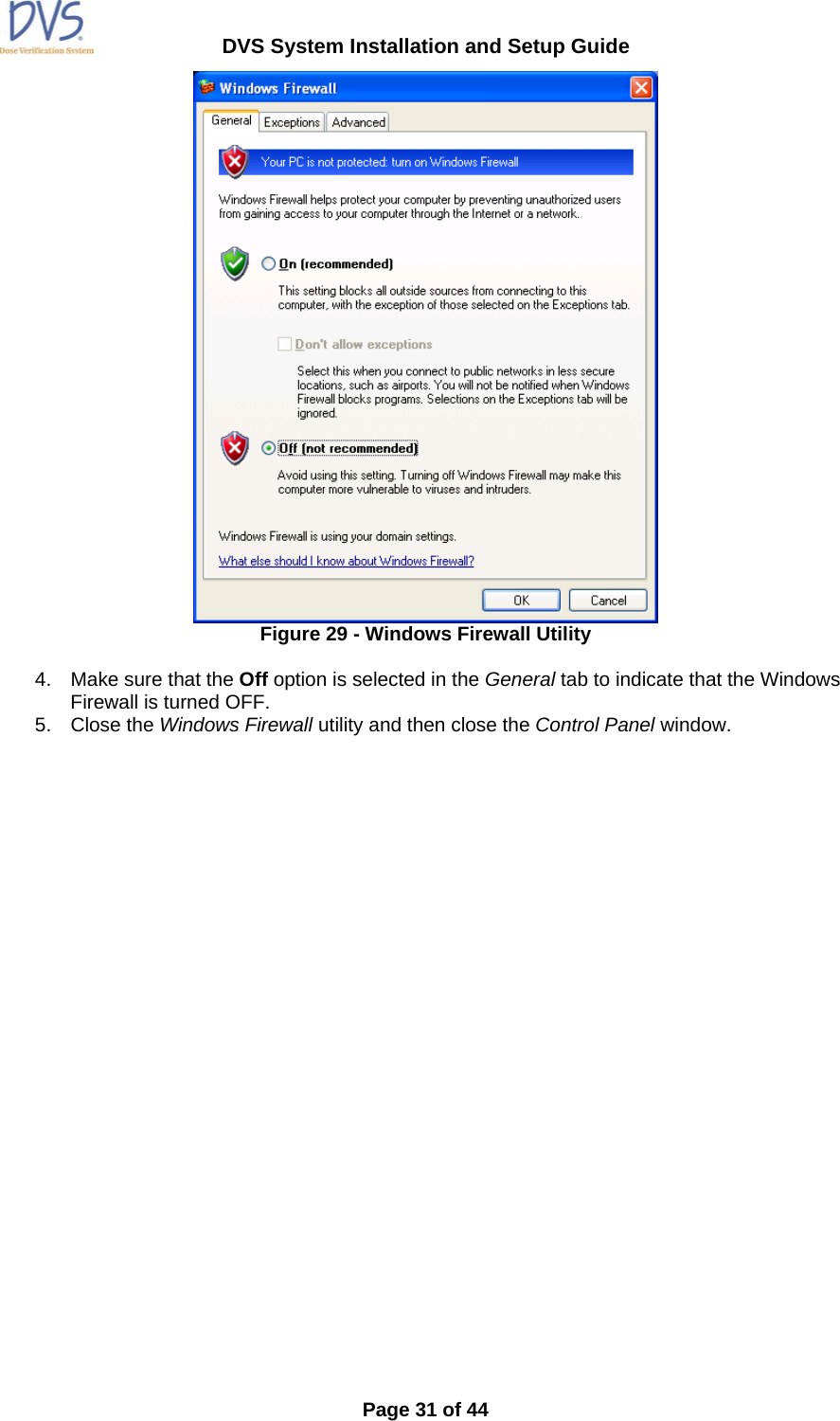
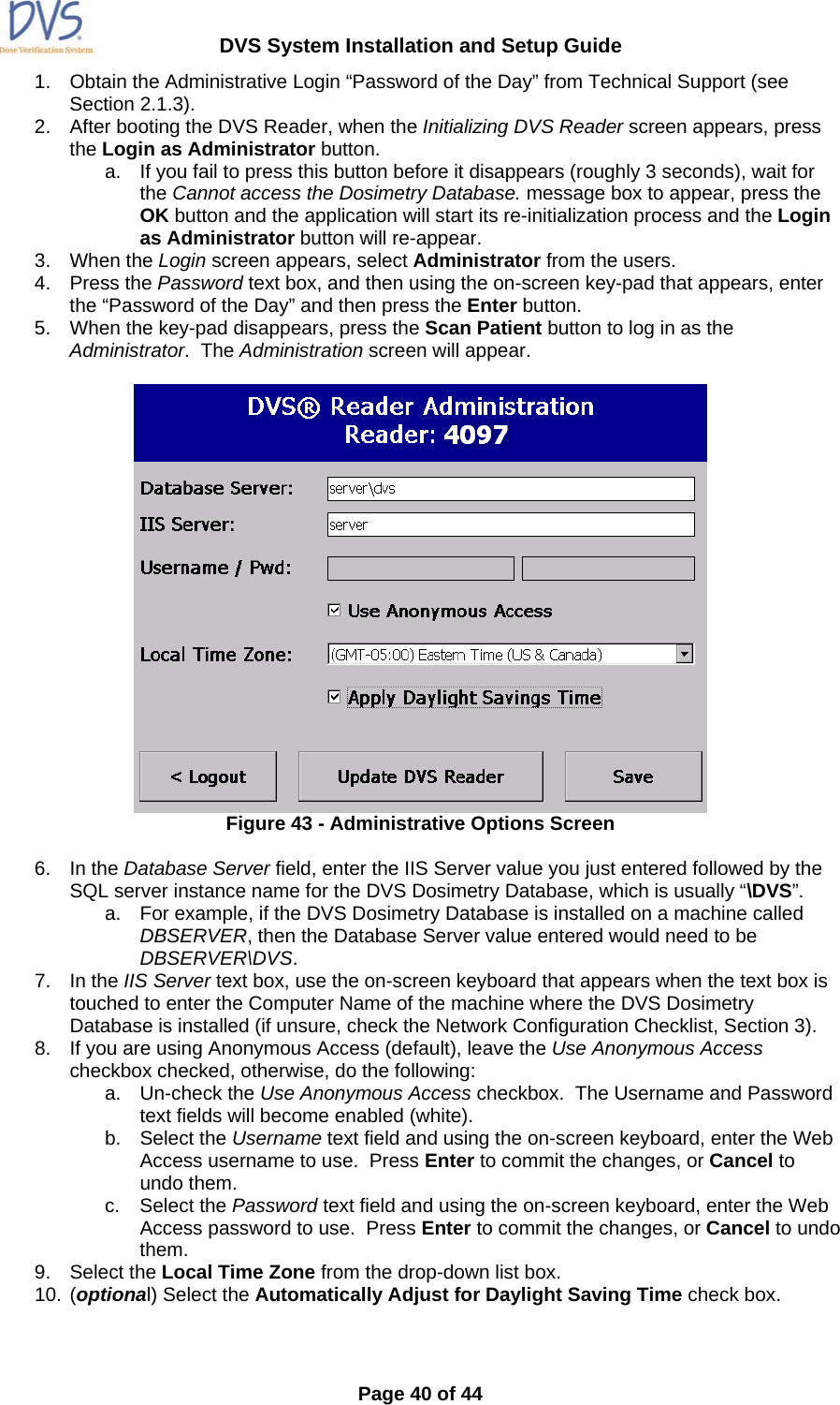
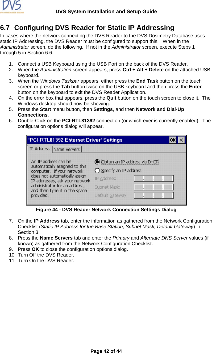
![DVS System Installation and Setup Guide Page 11 of 44 Guidance and Manufacturer’s Declaration – Electromagnetic Immunity The DVS-R-200 is intended for use in the electromagnetic environment specified below. The customer or the user of the DVS-R-200 should assure that it is used in such and environment. Immunity Test IEC 60601 test level Compliance level Electromagnetic environment – guidance Portable and mobile RF communications equipment should be used no closer to any part of the DVS System, including cables, than the recommended separation distance calculated from the equation applicable to the frequency of the transmitter. Recommended separation distances Conducted RF IEC 61000-4-6 3 Vrms 150 kHz to 80 MHz [3] V Pd ⎥⎦⎤⎢⎣⎡=35.3 Radiated RF IEC 61000-4-3 3 V/m 80 MHz to 2,5 GHz [3] V/m Pd ⎥⎦⎤⎢⎣⎡=35.3 80 MHZ to 800 MHz Pd ⎥⎦⎤⎢⎣⎡=37 800 MHz to 2,5 GHz where P is the maximum output power rating of the transmitter in watts (W) according to the transmitter manufacturer and d is the recommended separation distance in metres (m). Field strengths from fixed RF transmitter, as determined by an electromagnetic site survey a, should be less than the compliance level in each frequency range. b Interference may occur in the vicinity of equipment marked with the following symbol: Note 1 At 80 MHz and 800 MHz, the higher frequency range applies. Note 2 These guidelines may not apply in all situations. Electromagnetic propagation is affected by absorption and reflection from structures, objects and people. a field strengths from fixed transmitters, such as base stations for radio (cellular/cordless) telephones and land mobile radios, amateur radio, AM and FM radio broadcast and TV broadcast cannot be predicted theoretically with accuracy. To assess the electromagnetic environment due to fixed RF transmitters, and electromagnetic site survey should be considered. If the measured field strength in the location in which the DVS-R-200 is used exceeds the applicable RF compliance level above, the DVS-R-200 should be observed to verify normal operation. If abnormal performance is observed, additional measures may be necessary, such as re-orienting or relocating the DVS-R-200. b Over the frequency range 150 KHz to 80 MHz, field strengths should be less than 3 V/m. IEC 60601-1-2 Table 4](https://usermanual.wiki/Sicel-Technologies/DVS-R-200.Installation-Manual/User-Guide-1001273-Page-12.png)