Contents
user manual

State: 2010-03-01
Vers. no.: 1.10
m. dudde hochfrequenz-technik Rottland 5a D-51429 Bergisch Gladbach/ Germany Tel. +49 2207-96890 Fax +49 2207 968920
Annex no. 5
User Manual
Subject to change without noticeSICK AGWaldkirchGermanywww.sick.com
Correct use
The RFH630 interrogator is an intelligent sensor for
automatic, xed identication and data feeding of wireless
data carriers on moving or stationary objects. The RFH630
is designed as a compact read/write unit with integrated
antenna and operates with all standard ISO/IEC15693-
compatible transponders in the frequency range 13.56 MHz,
wither as a standalone device or coupled into a network. The
RFH630 uses its host interface to transmit the read results to
an overriding computer for further processing or it can receive
corresponding commands for editing the data carrier (read,
write, etc.).
The purpose of this instruction manual is to allow you to put
the RFH630 into operation quickly and easily and to achieve
initial read results with transponders. They describe the com-
missioning process for an application with a single RFH630.
The technical information contains more detailed information
pertaining to the mechanical and electrical installation for the
RFH630. Detailed information about conguration is available
in the online help function of the SOPAS ET conguration
software.
All information can be accessed on the enclosed data carrier
(DVD) or from the product site on the web (www.mysick.com/
de/RFH6xx).
Safety information
• Read these instructions before commissioning the
RFH630 in order to familiarize yourself with the device and
its functions.
• Electrical connections between the RFH630 and other
devices may only be connected or disconnected when the
system is not live. Otherwise the devices may be damaged.
• Wire cross sections of the supply cable from the cus-
tomer's power system should be designed in accordance
with the applicable standards.
• Only use the RFH630 under permissible ambient condi-
tions (e.g. temperature, ground potential) ( see "Device
structure RFH630", page 5).
• Protect the RFH630 against moisture and dust when the
cover to the MicroSD card slot is open. The cover on the
housing must be secured with screws in order to comply
with enclosure rating IP 67 in operation. The same applies
for protective caps/plugs on unused electrical connec-
tions.
• Do not open the RFH630 housing. If opened, any warranty
claims against SICK AG are void.
Commissioning and conguration
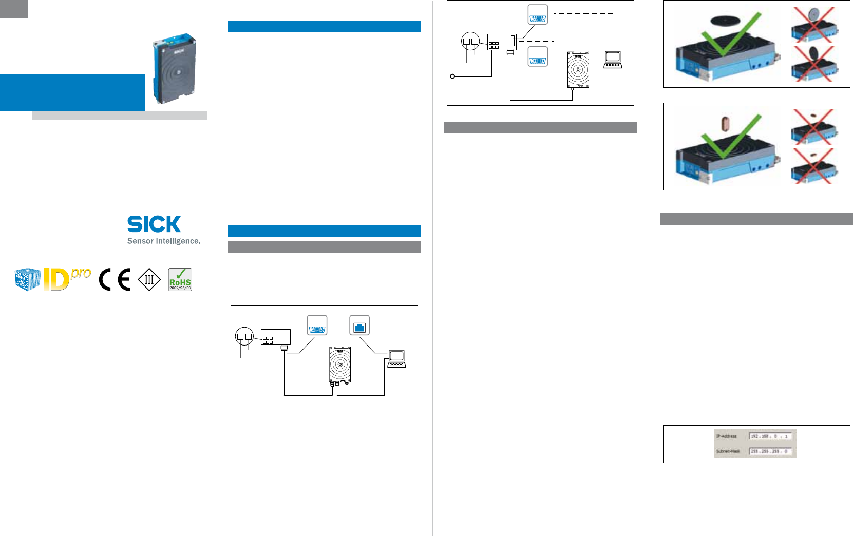
Step 1: Electrical installation
1. Connect the communication interface of the RFH630 to
the PC (e.g. Ethernet).
2. If the external antenna is being used (e.g. RFA332-2032,
No. 1054399), connect it to the antenna input on the
RFH630-1102101.
Connection Module
CDB620-001
SOPASSOPAS
RFH630
12
DC 10 ... 30 V
GND
Configuration
Diagnostics
Power e.g. Ethernet
e.g. cable
No. 2055419 (2 m)
e.g. cable
No. 6034414 (2 m)
EthernetEthernet
SerialSerial
...
...
PC
Electrical connection RFH630-1102101
Connection Module
CDB620-001
SOPASSOPAS
RFH630
12
DC 10 to 30 V
GND
Configuration
Diagnostics
SerialSerial
...
...
e.g. no. 1042256
Power/Serial Data/
CAN/I/O (AUX, HOST)
PC
e.g. cable
no. 2014054 (2 m)
„Serial RS-232“ (AUX)
DC 10 ... 30 V
SerialSerial
Electrical connection RFH630-1000001
Step 2: Mounting and alignment
1. Fix the mounting kit (optional accessory no. 2048551) to
the RFH630.
( see Technical Information, "Mounting" chapter).
Alternatively, mount the RFH630 with 3 screws type M6
to a bracket supplied by the customer. Screw in the M6
screws to max. 6.5 mm into the mounting thread ( see
"Device description", page 2).
2. Align the surface of the integrated antenna on the RFH630
(front face) and where applicable the external antenna of
the data carrier to the object. In doing so, take into con-
sideration the alignment and dimensions of the antenna
lobes. Avoid as far as possible any large metal surfaces
positioned to the front.
3. Supply power to the RFH630.
After successful initialization, the "Ready" LED illuminates
green.
4. Ensure that no electrically conductive objects are posi-
tioned between the RFH630/antenna and the transponder
during the read/write process. This would attenuate the
generated HF eld and thereby reduce the range of the
RFH630.
Scanning range of the read/write eld on the RFH630
The maximum scanning range for communication between
the RFH630 and transponder depends on various factors.
Primarily, the dimensions of the transponder's antenna
positively affects the scanning range. An additional factor
for the scanning range is the quality of the transponder, for
example, the antenna gain, the integrated transponder IC and
its associated sensitivity. The specic reading eld diagrams
are available on the product website (www.mysick.com). The
diagrams shown on page 4 depict the associated reading
ranges for three different transponders ( see "Reading eld
diagrams RFH630", page 4).
Important
The specied values can only be achieved if the transponder
is aligned parallel and evenly to the RFH630 antenna.
Alignment of RFH630 for discs, coins and ISO cards
Alignment of RFH630 for on-metal transponders and glass transpon-
ders
Step 3: Conguration to PC
Conguration of the RFH630 to the application as well as
diagnostics in the event of malfunctions is undertaken by
default with the SOPAS ET conguration software.
Install and launch the SOPAS ET conguration software
1. Install the software on the PC from the enclosed "Software
& Manuals Auto Ident" DVD (alternatively, download and
install it from the website "www.sick.com/software-und-
downloads"). In this case, select the "Complete" option as
selected by the install wizard. Administrator rights may be
required on the PC to install the software.
2. Start the "SOPAS ET" program after completing the instal-
lation.
Path: Start > Programs > SICK > SOPAS ET Engineering
Tool > SOPAS.
3. Establish communication between SOPAS ET and RFH630
with the automatically launching wizard. In order to do so,
select the available devices in accordance with the con-
nected data interface, e.g. Ethernet on the RFH630.
4. The following IP address is congured by default on the
RFH630:
5. SOPAS ET establishes communication with the RFH63x
and loads the associated device description le for the
RFH63x. The "Quickstart" tab opens automatically.
RFID Interrogator (HF)
EN
DRAFT
Subject to change without noticeSICK AGWaldkirchGermanywww.sick.com
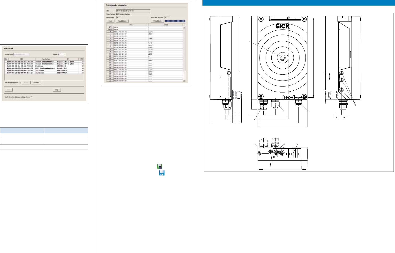
Identifying the transponder
1. Bring one or more standards-compliant HF transponders
into the working area of the internal antenna or where ap-
plicable the external antenna of the RFH630.
2. Click the "Start" button on the Quickstart page of the
SOPAS ET. SOPAS ET generates an automatic reading cycle
and lists the identied transponders one after the other on
the Quickstart page.
SOPAS ET Program Window
Display of six identied transponders in the Quickstart window
The process feedback LED in the center of the RFH630
device cover signies in the default conguration if an HF eld
is available and a transponder is detected.
Lamp signal behavior blue LED Meaning
Lights up with medium intensity HF eld available
High intensity slow ashing 1 transponder in eld
High intensity rapid ashing More than 1 transponder in eld
Accessing the data on a transponder
1. In order to access the memory area of a transponder in
the RFH630 database (read/write), click the stop button
in Quickstart.
2. Mark the desired transponder (click it with the mouse).
3. Click the transponder access button.
The transponder user data tab displays the content of the
selected transponder.
Display window transponder user data
Important
The UID (Unique Identier) of the transponder cannot be
changed.
Continuing conguration
1. Use the navigation tree in SOPAS ET and with the help of
the other entries under parameter, edit the required tabs
for the application (among other things, transponder com-
munication, trigger control, data processing and output,
data output interface(s) as well as switching inputs and
outputs.
2. Test and if necessary modify the settings made when
operating the system under real conditions.
Complete the conguration
>Permanently save the entire conguration:
Parameter set in RFH630: click the button
Conguration le on the PC: click the button.
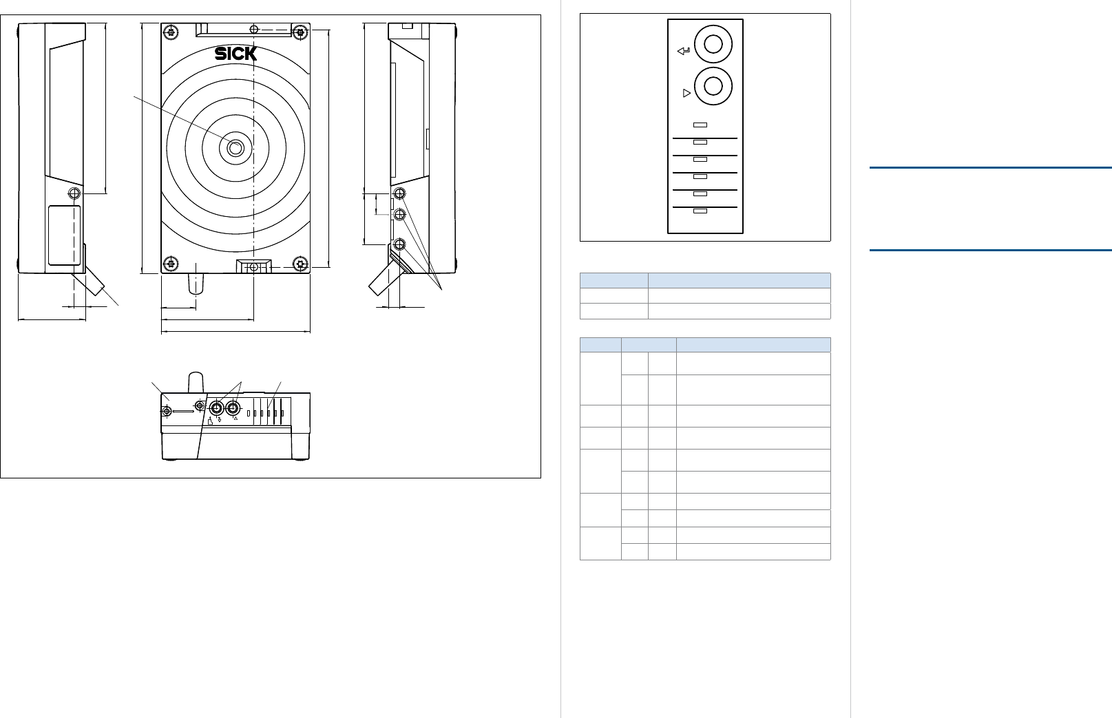
Description of the device
Device structure RFH630-1102101
39.3 16.1
6.5 10.4
17.4 147
100
100
139.6
12.5
30
7.8
20.6
54.5
71.9
6.4
9.1
87.5
12.3
5
34 7
6
1
2
8
mircoSD
Ready
Result
LNK TX
CAN
Data
RF
Read Diagn
Antenna
Sync
Userdef.
TeachIn
Enter
Stop
1 connection "Power / Serial Data / CAN / I/Os"
(17-pin M12-plug, A-coded)
2 "Ethernet" connection (4-pin M12 socket, D coded)
3 Function keys ▾ (Step) and p (Enter)
4 Slot for MicroSD card, behind threaded cover
5 Process Feedback LED
6 Antenna output (TNC socket)
7 6 x status LEDs
8 Mounting thread M6, 6.5 mm depth
DRAFT
Subject to change without noticeSICK AGWaldkirchGermanywww.sick.com
Device structure RFH630-1000001
39.3
6.5
147
100
100
139.6
12.5
30
20.7
54.5
6.5
87.5
mircoSD
Ready
Result
LNK TX
CAN
Data
RF
Read Diagn
Antenna
Sync
Userdef.
TeachIn
Enter
Stop
4
23 5
1
6
1 Cable 0.9 m with D-Sub-HD plug (15-pin)
2 Function keys ▾ (Step) and p (Enter)
3 Slot for MicroSD card, behind threaded cover
4 Process Feedback LED
5 6 x status LEDs
6 Mounting thread M6, 6.5 mm depth
Status indicators, function keys, functions
Ready
Result
LNK TX
CAN
Data
RF
Read Diagn
Antenna
Sync
Userdef.
TeachIn
Enter
Stop
LED status indicators and function keys
Key Function
▸ Select function.
p Start or quit function.
Display LED Status
OGreen Lights up constantly after switching on
and completion of successful self-test.
Goes out when downloading or upload-
ing conguration data from and to the
RFH630
OGreen Successful read process
(good read, 100 ms)
OGreen Antenna eld activated
(dependent on read cycle)
Green Data transfer via serial host interface
(RxD)
Yellow Data transfer via serial host interface
(TxD)
OGreen CAN-interface activated
Green Data transfer via CAN interface
Green Data transfer via Ethernet interface
OYellow Physical Ethernet connection
O = illuminated; = ashes
MicroSD memory card (optional accessory)
Function
An insertable memory card can be used with the RFH630
to store the last modied parameter set (cloning). The
memory card is not included in the scope of delivery.
Insert memory card
Only use types approved by SICK to ensure reliable function
of the memory card.
The card slot ( see "Device Description", page 2) can be
accessed on the RFH630 behind the aluminum cover.
NOTE
Risk of data loss or irreparable damage to the memory
card
>Never remove the memory card during the write process.
>Do not turn off the supply voltage.
DRAFT
Subject to change without noticeSICK AGWaldkirchGermanywww.sick.com
Overview of pin assignment
4
3
2
1TD+
TD–
RD+
RD–
4
3 2
1
Connection “Power/Serial Data/CAN/I/0” Ethernet connection
17-pin plug on RFH630 4-pin socket on RFH63015-pin plug on cable e.g. no. 2055419 (2 m)
CAN L
CAN H
TD+ (RS-422), HOST
TD– (RS-422),
TxD (RS-232), HOST
DC 12 to 30 V
TxD (RS-232), AUX
RxD (RS-232), AUX
RD+ (RS-422), HOST
GND
RD– (RS-422),
RxD (RS-232), HOST
Result 1 (switch output 1)
Result 2 (switch output 2)
7
6
Sensor 2 (switch input 2)
Sensor 1 (switch input 1)
SensGND
4
3
2
1
5
8
9
10
11
12
13
14
15
CAN L
CAN H
TD+ (RS-422), HOST
TD– (RS-422),
TxD (RS-232), HOST
DC 12 to 30 V
TxD (RS-232), AUX
RxD (RS-232), AUX
RD+ (RS-422), HOST
GND
RD– (RS-422),
RxD (RS-232), HOST
Result 1 (switch output 1)
n. c.
n. c.
Result 2 (switch output 2)
7
6
Sensor 2 (switch input 2)
Sensor 1 (switch input 1)
SensGND
4
3
2
1
5
8
9
10
11
12
13
14
15
16
17
6110
5
11 15
D-Sub-HD
87 15
614
5
17
4
13
3
2
12
1
11
10
9
16
M12, A coded
M12,D coded
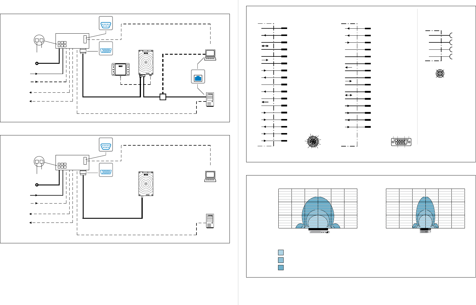
Reading eld diagrams RFH630
Coin 16
Disc 30
ISO Card
300
200
100
0
0–100–200–300 100 200 300
Reading field width in mm
Reading distance
in mm
300
200
100
0
0–100–200–300 100 200 300
Reading field width in mm
Reading distance
in mm
RFH630 RFH630
Overview of all interfaces and connection options
RFH630-1102101
„Ethernet“ (HOST)
read result
Input 2
(e.g. encoder)
Input 1
(e.g. external read cycle)
Output 1
(e.g. LED)
Output 2
RFU630
e.g. cable no. 2055419 (2 m)
Serial RS-232/422/485 (HOST), read result alternative to Ethernet
CDB620-001
SerialSerial
e.g. cable
no. 6034414 (2 m)
Configuration
Diagnostics
SOPASSOPAS
EthernetEthernet
SerialSerial
„Power/Serial Data/CAN/I/O“
(AUX, HOST)
e.g 1042256
...
...
12
DC 10 to 30 V
GND
HOST
PC
Further
data processing
e.g. cable no. 2014054 (2 m)
Serial RS-232 (AUX), alternative to Ethernet AUX-Port
Ethernet (AUX)
DC 10 to 30 V
inputs/outputs = digital
Additional excternal inputs/outputs
via parameter storage module CMC600
External antennnas
(optional e.g. RFA332)
RFH630-1000001
Input 2
(e.g. encoder)
Input 1
(e.g. external read cycle)
Output 1
(e.g. LED)
Output 2
RFU630
Serial RS-232/422/485 (HOST)
CDB620-001
SerialSerial
Configuration
Diagnostics
SOPASSOPAS
SerialSerial
„Power/Serial Data/CAN/I/O“
(AUX, HOST)
e.g 1042256
...
...
12
DC 10 to 30 V
GND
HOST
PC
Further
data processing
e.g. cable no. 2014054 (2 m)
Serial RS-232 (AUX)
DC 10 to 30 V
inputs/outputs = digital
Additional excternal inputs/outputs
via parameter storage module CMC600
DRAFT
Subject to change without noticeSICK AGWaldkirchGermanywww.sick.com
Items supplied
• RFH630 of the type ordered, equipped with protective
caps / plugs on the electrical connections
• "Software & Manuals Auto Ident" DVD (no. 2039442)
• Printed operating instructions in German and English; in
other languages as PDF on the DVD if required
• Optionally ordered accessories if applicable
Maintenance and care
The RFH630 does not contain any components that require
maintenance.
Sources for obtaining additional information
Additional information about the RFH630 and its optional
accessories can be found in the following places:
"Software & Manuals Auto Ident" DVD (no. 2039442)
• RFH630 technical information (supplementary informa-
tion, e.g. for mounting, electrical installation)
• These operating instructions in German and English
• Conguration software SOPAS ET with integrated online
help function
• Ordering information in the product information RFH630
• Product catalog identication solutions
• Publications dealing with the accessories
Product web page for the RFH630
(www.mysick.com/de/rfh63x)
• Suitable accessories
• Detailed technical specications (online data sheet)
• Dimensional drawing and 3D CAD dimension models in
various electronic formats
• Product catalog identication solutions
• RFH630 product information
• RFH630 operating instructions in German and English, in
other languages if necessary
• EC-Declaration of Conformity
• SOPAS ET conguration software updates
• All publications contained on the aforementioned DVD
(via links)
Support is also available from your sales partner: www.sick.
com/worldwide.
Documents on request
• Overview of RFH630 command strings
Support is also available from your sales partner:
www.sick.com/worldwide.
Model name RFH630
RFH630-1102101:
• 712 g
RFH630-1000001:
• 756 g
IP 67 (EN 60529: 1991-10/A2: 2000-02)
Operation: –20 °C to +50 °C
Storage: –25 °C to +70 °C
0 to 95%, non-condensing
EN 60068-2-6: 2008-02
EN 60068-2-27: 2009-05
III, (EN 61140: 2011-01)
EN 60950-1: 2006-04/A11: 2009-03
EN 301 489-3 V1.4.1 Receiver Class 2
Europe EN 300 330-2 (V1.5.1)/FCC Part 15
1) with RFID ISO card transponder in plane parallel alignment to RFH630
antenna; depending on dimensions and quality of transponder
For further technical specications, see the Online data sheet
on the product site on the web (www.mysick.com/de/rfh63x)
Warnings
aaWARNING
Danger of potential equalization currents
The RFH630 is designed to be operated in a system with
procient grounding of all connected devices and mounting
surfaces to the same ground potential. If this condition is not
met, potential equalization currents may ow along the cable
shields, leading to the following dangers:
• Dangerous contact voltage on the metal housing
• Malfunction or destruction of the RFH630
• Heating of the cables until spontaneous combustion
>See the "Electrical installation" chapter in the Technical
information on the enclosed DVD or on the product site
on the web (www.mysick.com/de/rfh63x) for measures to
eliminate hazards.
FCC approval
The RFH630 fullls part 15 of the FCC regulations:
The following prerequisites must be met:
• This device may not cause harmful interference, and
• this device must accept any interference received, includ-
ing interference that may cause undesired operation.
• Any changes or modications not expressly approved by
the party responsible for compliance could void the user's
authority to operate this equipment.
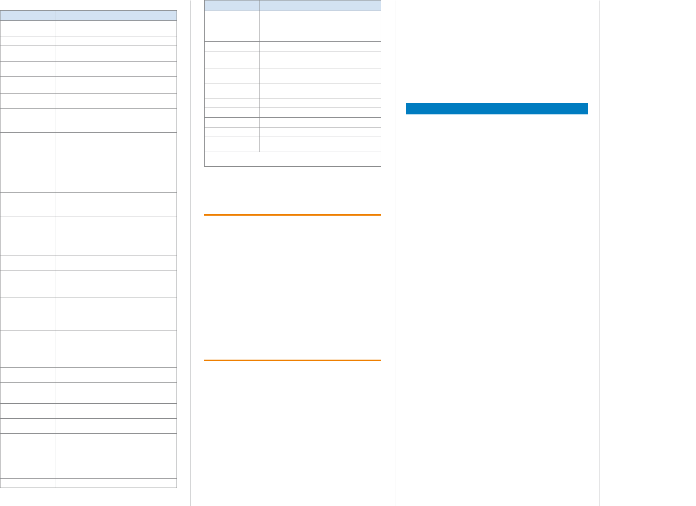
Technical specications (excerpt)
Model name RFH630
ISO/IEC 15693 Interrogator
(read/write unit)
HF (13.56 MHz)
ISO/IEC 1569, 18000-3M1 ("mandatory" and
"optional" command set)
1000 mW
Internal antenna: up to 240 mm
External antenna: RFA332: up to 360 mm
26 kBit/s
UID read (64 bit/8 byte): 18 ms
1 block read (32 bit/4 byte): 13 ms
1 Block write (32 bit/4 byte): 16 ms
RFH630-1000001:
• RS-232/422/485 (0.3 to 115.2 kBd)
• CANopen (20 to 1000 kBd)
RFH630-1102101:
• RS-232/422/485 (0.3 to 115.2 kBd)
• Ethernet TCP/IP (10/100 MBit/s)
• Ethernet IP (10/100 MBit/s)
• CANopen (20 to 1000 kBd)
PROFIBUS via CDF600-0100
PROFINET via CDM425
EtherCAT via CDF600-0300
RFH630-1000001:
• RS-232 (57.6 kBd)
RFH630-1102101:
• RS-232 (57.6 kBd)
• Ethernet TCP/IP (10/100 MBit/s)
Via CAN interface
2 x IN (Ue = max. 32 V, Ie = max. 5 mA), opto-
decoupled, debouncing time congurable,
2 additional inputs via module CMC600 in
module CDB620
2 x OUT (each Ia = ≤ 100 mA), not galvanically
isolated from the supply voltage, short-circuit
protection/temperature protection, 2 ad-
ditional inputs via module CMC600 in module
CDB620
Beeper, function congurable via SOPAS
1 x LED (Process Feedback) center front, func-
tion/color congurable via SOPAS
6 x LEDs for status signaling (Ready, Result,
RF, Data, CAN, LNK TX)
2 x, Read Diagnosis, additional functions
congurable via SOPAS
MicroSD card (optional) or external via module
CMC600 in connection module
CDB620-001
DC 10 ... 30 V, PELV according to EN 61140
(2002-03)
Max. < 6 W (with output signal switching
device unloaded and full transmission power)
RFH630-1102101:
• 1 x 17-pin. M12 round plug
• 1 x 4-pin. M12 round socket
• 1 x TNC
RFH630-1000001:
• 1 x 15-pin. Cable with D-sub-HD plug
Cast aluminum, plastic (PPS)
DRAFT

Subject to change without noticeSICK AGWaldkirchGermanywww.sick.com
8014953/2012-03-14 ∙ BGA/HE ∙ Printed in Germany (2012-03) ∙ All rights reserved ∙ Subject to change without notice
DRAFT