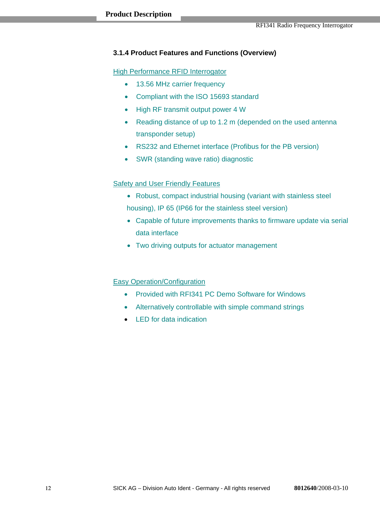
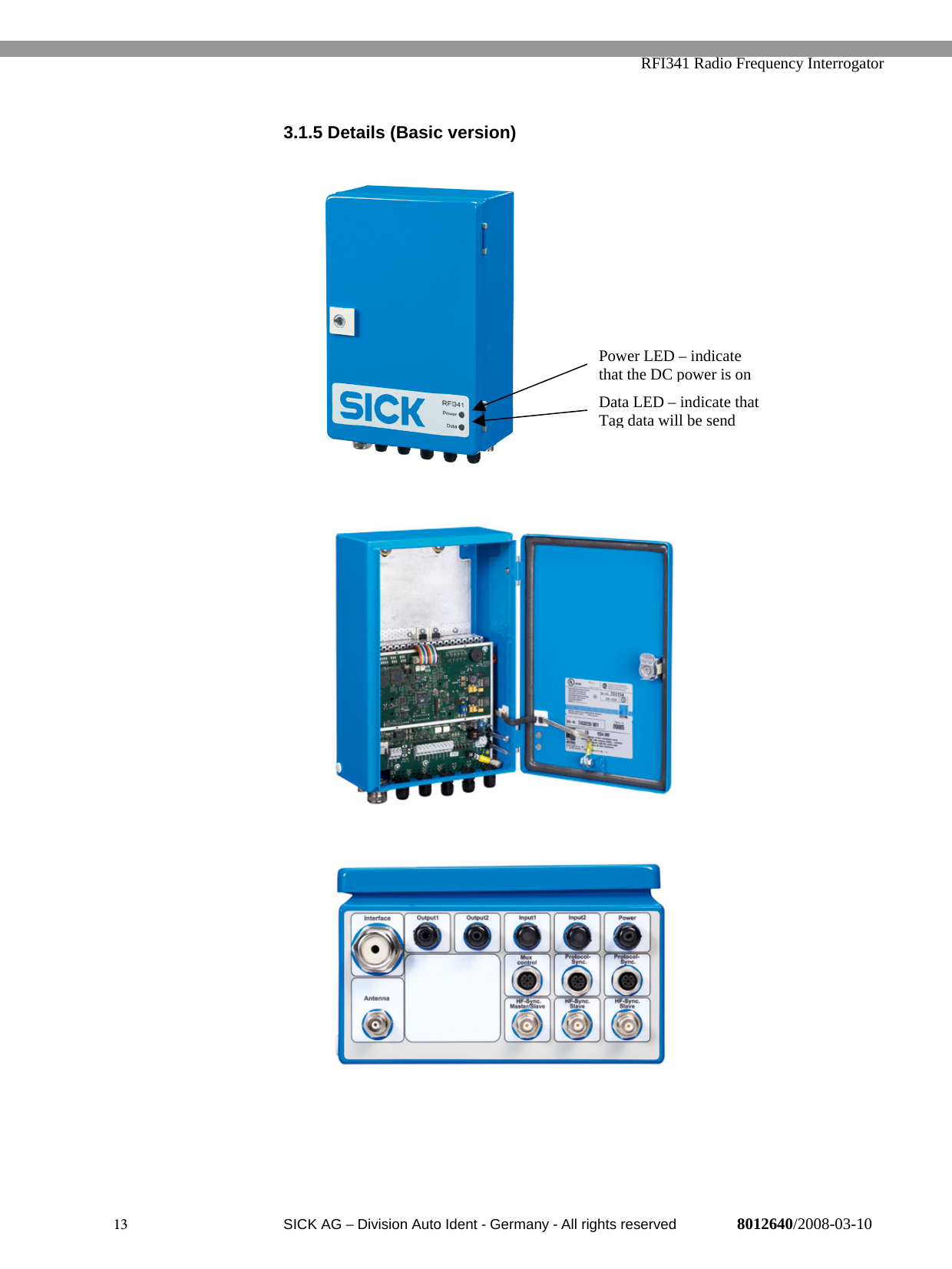
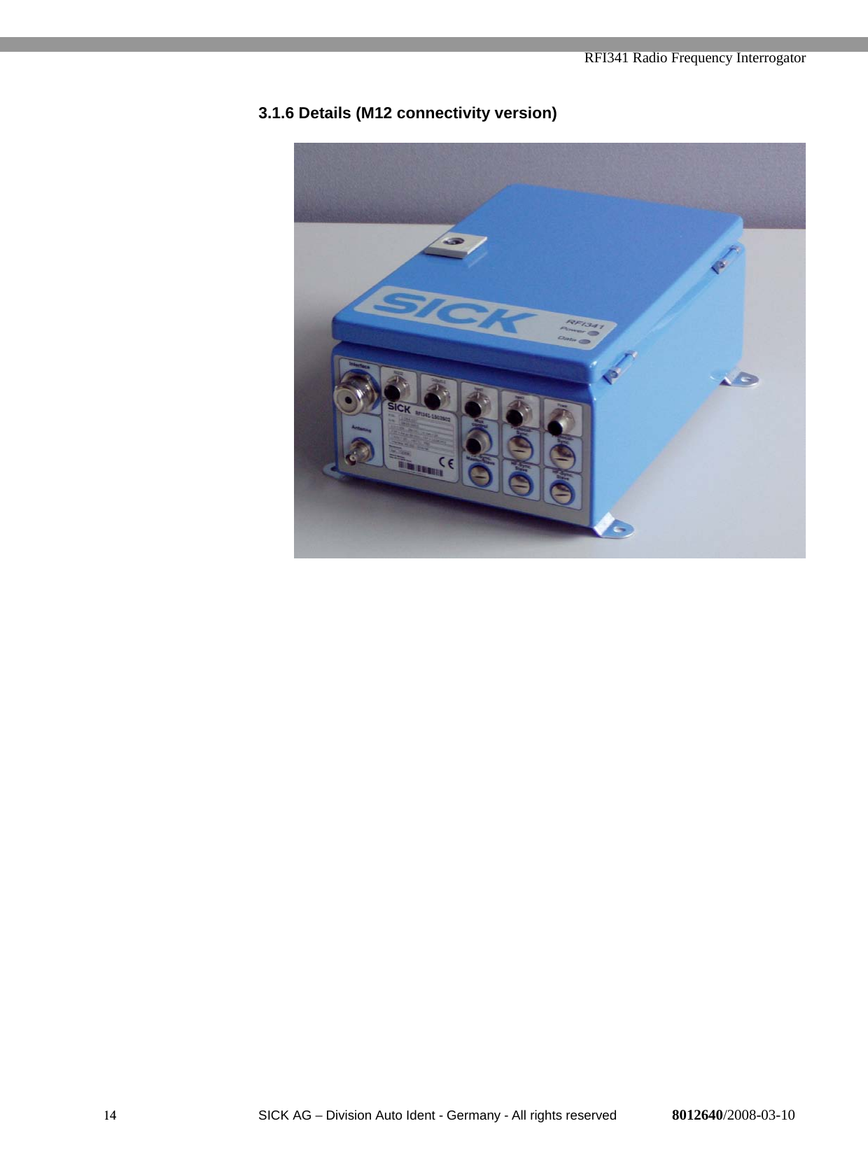
Sick RFI3411503S04 RFID (Radio frequency interrogator) User Manual Users manual

Sick AG RFID (Radio frequency interrogator) Users manual

Users manual

Annex No.5 Page 1 of 46                     Functional description  RFI341-1503S04
Preliminary8012640/2008-03-10 © SICK AG • Division Auto Ident • Germany • All rights reservedOPERATING INSTRUCTIONSRFI341-1503Radio Frequency Interrogator
  RFI341 Radio Frequency Interrogator2  SICK AG − Division Auto Ident - Germany - All rights reserved 8012640/2008-03-10Software VersionsSoftware VersionDSP Firmware V1.2.10ARM7 Firmware V0.24CopyrightCopyright © 2007SICK AG WaldkirchAuto Ident, Reute PlantNimburger Strasse 1179276 ReuteGermanyTrademarksWindowsTM is a registered trademark or trademark of the Microsoft Corporation inthe USA and other countries.Latest Manual VersionFor the latest version of this manual (PDF), see www.sick.com. Software Versions
  RFI341 Radio Frequency Interrogator3  SICK AG − Division Auto Ident - Germany - All rights reserved 8012640/2008-03-10ContentsSOFTWARE VERSIONS 2ABOUT THIS DOCUMENT 61.1 Purpose 61.2 Target Application Group 61.3 Symbols used 6SAFETY INFORMATION 72.1 Authorized Personnel 72.1.1 Assembly and maintenance 72.1.2 Electrical Connection and Replacement 72.1.3 Start-up, Operation and Configuration 72.1.4 Intended Use 82.2 General Safety Instructions and Protective Measures 92.3 Quick Stop and Restart 92.4 Environmental Conditions 92.4.1 Power Requirements 92.4.2 Disposal after Final Placing out of Operation 9PRODUCT DESCRIPTION 103.1 Design 103.1.1 Scope of Delivery 103.1.2 Variants 113.1.3 System Requirements 113.1.4 Product Features and Functions (Overview) 123.1.5 Details (Basic version) 133.1.6 Details (M12 connectivity version) 143.1.7 Details (Profibus stainless steel version) 15Inside View (main board, profibus CMF gateway, Profibus connection) 153.1.7 Details (FCC Version) 163.1.8 View of Details (Splitter) 183.1.9 View of Details (Mutliplexer) 183.2 Functional Description of the device 193.3 Operating Elements and Indicators 203.3.1 Operating Elements 203.3.2 Function of the LEDs 214. ASSEMBLY 224.1 Overview about the Assembly Steps 224.2 Preparation for Installation 224.2.1 Component required 224.2.2 Accessories 22Content
  RFI341 Radio Frequency Interrogator4  SICK AG − Division Auto Ident - Germany - All rights reserved 8012640/2008-03-104.2.3 Selecting the Installation Location 224.2.4 Brackets 235. ELECTRICAL INSTALLATION 245.1 Overview of the Installation Steps 245.2 Electrical Connections (basic version) 245.3 Electrical Connections (M12 connectivity version) 255.4 Preparations for Electrical Installation 255.4.1 Requirements for the RS-232 HOST interface 255.4.2 Requirements for the Profi-Bus interface 255.4.3 Main Power supply 265.4.4 Connect the RS-232 interface 265.4.5 Connecting the “Input 1” Switching Input 275.4.6 Connecting the Switching Output 285.4.7 Ethernet 285.5 Performing Electrical Installation (Basic-Version) 295.5.1 Overview of the Connection Procedure 295.6 Performing Electrical Installation (Profibus-Version) 295.6.1 Overview of the Connection Procedure 295.6.2 Connect the earth ground 295.6.3 Connect the RS232 Interface 305.6.4 Connect the Profi-Bus Interface 30 OPERATION 316.1 Overview of the Start-up Steps 316.2 Factory Default Settings 316.3 Configuration (Parameterisation) 326.3.1 Antenna Output Power 326.3.2 RS232 Data Interface 326.3.3 Oscillator Switch off delay 336.3.4 Read after Write Verify 336.3.5 HF Reset for Inventory Commands 336.4 ISO/IEC 15693 settings 347. MAINTANANCE 357.1 Maintenance 357.2 Disposal 358. TROUBLESHOOTING 368.1 Installation errors 368.2 Electrical Connection Errors 368.3 Parameterisation Errors 36
  RFI341 Radio Frequency Interrogator5  SICK AG − Division Auto Ident - Germany - All rights reserved 8012640/2008-03-109. TECHNICAL DATA 379.1 RFI341-1503 379.2 Dimensional Drawing 3810. APPENDIX 3910.1 Accessories 3910.2 Glossary, Standard Basics, and Abbreviations 3910.3 ISO/IEC 15693 – ISO/IEC 18000-3 Mode 1 Basics 41
  RFI341 Radio Frequency Interrogator6  SICK AG − Division Auto Ident - Germany - All rights reserved 8012640/2008-03-101. About this Document1.1 PurposeThis document provides information on placing the RFI341 Interrogator.This document contains information about:• Mounting and electrical installation• Start-up• Use and configuration• Maintenance• Special applications and practices1.2 Target Application GroupThe target groups for this user guide are:• Operating electricians• Technicians and engineers1.3 Symbols usedSome of the information in this document is especially marked so that it canbe accessed quickly.Warning!Warnings are provided to prevent injury to operating personnel or seriousdamage to the RFID Interrogator.→ Always read warnings carefully and observe them at all times.Notes provide information on special features or characteristics.Explanations provide background information on technical aspects.Recommendations provide advice on how to carry out a task more effectivelyThis symbol refers to additional technical documentation.NoteExplanationRecommendationAbout this Document
  RFI341 Radio Frequency Interrogator7  SICK AG − Division Auto Ident - Germany - All rights reserved 8012640/2008-03-102. Safety Information2.1 Authorized Personnel•  For the RFI341 to function correctly and safely, it must be installedand operated by sufficiently qualified personnel.•  The end user must be supplied with the operating instructions.•  The end user must be provided with expert training and is advised toread the operating instructions.•  The following qualifications are required for the various tasksinvolved.2.1.1 Assembly and maintenance•  Practical basic technical training•  Knowledge of the standard guidelines relating to safety in theworkplace2.1.2 Electrical Connection and ReplacementPractical training in electrical technology•  Knowledge of the standard safety guidelines relating to electricaltechnology•  Knowledge regarding the operation of the devices in the relevantapplication (e.g. conveyor belt)2.1.3 Start-up, Operation and ConfigurationKnowledge regarding the operation of the devices in the relevant application(e.g. conveyor belt)•  Knowledge of the software and hardware environment of the relevantApplication•  Basic understanding of data transfer methods• Basic understanding of RFID technologySafety information
  RFI341 Radio Frequency Interrogator8  SICK AG − Division Auto Ident - Germany - All rights reserved 8012640/2008-03-102.1.4 Intended UseThe RFI341 is designed to detect and decode 13.56 MHz, ISO 15693compliant RFID transponder signals. It is used together with antennasinstalled in a reading station and reads from and writes to RFID transponderson objects positioned, e.g., on a conveyor belt.The RFI341 enables the bi-directional communication with a host for, e.g.,further processing.Any warranty claims against SICK AG will be rendered invalid if the device isused for any other purpose or if changes are made to the device includingchanges made during the installation and electrical connection procedures.Safety information
  RFI341 Radio Frequency Interrogator9  SICK AG − Division Auto Ident - Germany - All rights reserved 8012640/2008-03-102.2 General Safety Instructions and Protective MeasuresRead carefully the general safety instructions and observe them at all times.This also applies to the warnings provided for the activities described in eachchapter of this document.Risk of injury by electrical current!The power supply is connected to the main voltages 24V DC.→  When working with electrical equipment, always follow the relevantsafety instructions.2.3 Quick Stop and RestartSwitching off the power supply of the RFI341 can result in loss of thefollowing:•  The specific application parameter set, if it was set only temporarily•  The last reading in the result buffer2.4 Environmental ConditionsThe RFI341 is designed to cause minimum impact to the environment.2.4.1 Power RequirementsThe RFI341 has a maximum power consumption of 50W.2.4.2 Disposal after Final Placing out of OperationAlways dispose of unusable or irreparable devices in a manner that is notharmful to the environment and in accordance with the applicable nationalwaste disposal regulations. The RFI341 can be separated into recyclablesecondary raw materials and special category waste (electronic scrap).At present, SICK does not accept the return of unusable or irreparabledevices.Safety information
  RFI341 Radio Frequency Interrogator10  SICK AG − Division Auto Ident - Germany - All rights reserved 8012640/2008-03-103. Product DescriptionTHE RFI341 RFID System is used for wireless identification of a variety ofobjects. It works at a frequency of 13.56 MHz and reads passive ISO/IEC15693 tags. For a working RFID system, antennas and transponders as wellas a host computer are required in addition to the product itself.3.1 Design3.1.1 Scope of DeliveryIn the packaging, the RFI3411 is supplied with:- 3-core RS 232 data cable (9-pin Sub D socket, open end), length 1.5 m- An information sheet with terminal diagram and quick-start instructions- CD-ROM with:RFI341 PC Software for WindowsTMRFI341 Telegram ListingRFI341 Operating instructionsRFA3xx Antenna Operation InstructionsThe latest versions of all applicable publications/programs on the CD-ROMcan be also downloaded from www.sick.comChapter 10.1, “Accessories” provides an overview of the availableinstallation accessories and standard antenna types as well as measurementequipment and sensors for reading pulse generation.NoteProduct Description
  RFI341 Radio Frequency Interrogator11  SICK AG − Division Auto Ident - Germany - All rights reserved 8012640/2008-03-103.1.2 VariantsType Order No. DescriptionRFI341-1503 1043330 RFI341 13,56MHz basicRFI341-1503S01 1043981 RFI341; Stainless steel withintegrated ProfibusRFI341-1503S02 1044537 RFI341 with M12 connectivityRFI341-1503S04 1045449 RFI341 his device complieswith Part 15 of the FCC Rules.Operation is subject to thefollowing two conditions:Additional Filter to be used asshown in this spec. In case Muxis used the FCC Version needto be used.Splitter 6036000 One (4W) to two (2W) antennasplitter (passive) ; not for usewith ProfiBus-VersionMultiplexer 6036002 One (4W) to up to 4 Antenna(each 4W) mulitplexerMultiplexer FCC 6037325 FCC Version of the mulitplexerFilter FCC 6037324 Filter to be used in case FCCPart 15 need to be addressedAntenna adapter 2046653 Bulgin to BNC antennaconnector converter.Interface cableRS232 tbd M12 to RS232 interface cableInterface cable MuxControl 6035859 Control interface betweenRFI341 and external multiplexer3.1.3 System RequirementsThe following are required to start up and operate the RFI341:1.  24V DC mains power source2.  Using external clock pulse (start/stop interval) e.g. via the sensor inputs,suitable reading pulse sensors for signalling the presence of an object orthe end of a reading/writing interval, e.g., a photoelectric reflex switch arerequired.3.  A higher level computer (host system) with a Ethernet or RS232 to runthe PC Demo Software on a PC (Windows XP)4.  A SICK 13.56 MHz antenna, Type RFA3xxProduct Description
  RFI341 Radio Frequency Interrogator12  SICK AG − Division Auto Ident - Germany - All rights reserved 8012640/2008-03-103.1.4 Product Features and Functions (Overview)High Performance RFID Interrogator•  13.56 MHz carrier frequency•  Compliant with the ISO 15693 standard•  High RF transmit output power 4 W•  Reading distance of up to 1.2 m (depended on the used antennatransponder setup)•  RS232 and Ethernet interface (Profibus for the PB version)•  SWR (standing wave ratio) diagnosticSafety and User Friendly Features•  Robust, compact industrial housing (variant with stainless steelhousing), IP 65 (IP66 for the stainless steel version)•  Capable of future improvements thanks to firmware update via serialdata interface•  Two driving outputs for actuator managementEasy Operation/Configuration•  Provided with RFI341 PC Demo Software for Windows•  Alternatively controllable with simple command strings• LED for data indicationProduct Description
  RFI341 Radio Frequency Interrogator13  SICK AG − Division Auto Ident - Germany - All rights reserved 8012640/2008-03-103.1.5 Details (Basic version)Power LED – indicatethat the DC power is onData LED – indicate thatTag data will be send
  RFI341 Radio Frequency Interrogator14  SICK AG − Division Auto Ident - Germany - All rights reserved 8012640/2008-03-103.1.6 Details (M12 connectivity version)
  RFI341 Radio Frequency Interrogator15  SICK AG − Division Auto Ident - Germany - All rights reserved 8012640/2008-03-103.1.7 Details (Profibus stainless steel version)Inside View (main board, profibus CMF gateway, Profibus connection)
  RFI341 Radio Frequency Interrogator16  SICK AG − Division Auto Ident - Germany - All rights reserved 8012640/2008-03-103.1.7 Details (FCC Version)This device complies with Part 15 of the FCC Rules. Operation is subjectto the following two conditions:(1) This device may not cause harmful interference, and(2) this device must accept any interference received, including     interference that may cause undesired operation.Any changes or modifications not expressly approved by SICK AG couldvoid the user's authority to operate this equipment.To address the FCC requirements the power supply cable as well as theinterface cable must be a shielded version. It need  to be ensured, thatthe shield is direct connected to the PG glant.The FCC device is only addressing the FCC rules with the antennaRFA331-1020 and RFA341-3520.Usage of additional Filters required to address FCC rules. The number ofFilters required depends on the usage of external components/antennas:1.)  One antenna used direct at the antenna output of the RFI341 requirethe usage of an FCC Filter at the RFI341 antenna output.2.)  If the splitter is used a Filter is required at the RFI341 antenna output3.)  If a Multiplexer is used a Filter need to be used at the RFI341Antenna output and at each RF outputs of the Multiplexer.RFI341-1503S04ANTFilterRFI341-1503S04ANTSplitterANTRFI341-1503S04ANTMultiplexerANTFilterFilterFilterANT ANTFilterFilterStandard one antenna Splittertwo antenna Multiplexer1-4 antennaFilter
  RFI341 Radio Frequency Interrogator17  SICK AG − Division Auto Ident - Germany - All rights reserved 8012640/2008-03-10Inside view RFI341-1503S04 The FCC Version require a shielded power supply cable.Note
  RFI341 Radio Frequency Interrogator18  SICK AG − Division Auto Ident - Germany - All rights reserved 8012640/2008-03-103.1.8 View of Details (Splitter)3.1.9 View of Details (Mutliplexer)Mux Control interface –must be connected to theRFI Mux Control outputAntenna Mux input –must be connected to theRFI341 antenna outputMux – Antenna output 1 to 4Antenna input – must be connectedto RFI341 antenna output Antenna output – each0,5 x Tx input power
  RFI341 Radio Frequency Interrogator19  SICK AG − Division Auto Ident - Germany - All rights reserved 8012640/2008-03-103.2 Functional Description of the deviceThe device operates according the reader/interrogator “talks first” (ITF)method as defined in the ISO/IEC 15693 Standard. Each transponder inthe field remains silent until a request is received. The interrogator canidentify simultaneously a number of tags present in the antenna field. Theinterrogator can write data to and read data from the transponders.Transponders can be addressed by e.g. using the factory programmed,unique read only number (64 bit length). If the data in the user memory ofthe tag are not write protected, the read/write feature enables therewriting of the data stored in this memory.The RFI341 is controlled by the data interface. The commands aredescribed in the document “Telegram Listing RFI341” which enables theuse of the features defined in ISO/IEC 15693. Additional commandssupport the use of sensor inputs and/or actuators. After configuration thedevice could either work in a mode where the host in controlling the unitor in trigger mode. Configuration in trigger mode means: The device iswaiting for a start condition to start reading automatically. Reading resultswill be transmitted directly or with closing the read window. If the deviceis running in background mode only a valid escape sequence willterminate this and brings the device back in command mode (see alsotelegram listing).To start a reading process, when an object with a transponder is in thefield, the RFI341 must be clocked by one of the following:•  A command sequence via the data interface•  The execution (based on a suitable trigger) of a previouslydefined background commandIf a transponder is detected, the relevant data can be send via the datainterface to the host. The “Data LED” indicates the presence of tag data.Product Description
  RFI341 Radio Frequency Interrogator20  SICK AG − Division Auto Ident - Germany - All rights reserved 8012640/2008-03-103.3 Operating Elements and Indicators3.3.1 Operating ElementsThe RFI341 is operated and configured via the data interface (host) usingthe PC Demo Software (RS232), or command strings send via the hostinterface. A variety of parameterisation options allows for the adaptationof the device to a wide range of applications.The following can be set:ISO Settings including:• Modulation depth•  Tag modulation type•  Tag data rate•  AFI (Application Field Identifier)•  DSFID (Data Storage Field Identifier)RFI341 Settings Including:•  RF output power•  Communication parameters for the interface•  Switching on of the RF field (test)•  Port time-out valueDetailed information could be found in the telegram listingProduct Description
  RFI341 Radio Frequency Interrogator21  SICK AG − Division Auto Ident - Germany - All rights reserved 8012640/2008-03-103.3.2 Function of the LEDsThe RFI341 does have several LEDs on the main PCB board. A few ofthem could be useful for device service functions.Closed to the terminals there is an indicator for:•  RXT and TXD (Data will be sent from and to Host)•  Input and output LED’s indicate the status of the IN/OUT ports•  LED bar indicates the SWR value if measurement manuallyactivatedProduct Description         Out-1 Out-2 In-1 In-2LED: TXD  RXDPower LED‘sLED’s forSWRmeasurement
  RFI341 Radio Frequency Interrogator22  SICK AG − Division Auto Ident - Germany - All rights reserved 8012640/2008-03-104. Assembly4.1 Overview about the Assembly Steps•  First, select the installation location for the RFA3xx antenna•  Select the installation location for the RFI341•  If used, select the installation location for the sensor(s)4.2 Preparation for Installation4.2.1 Component required• RFI341• RFA3xx (antenna)• Antenna connector converter•  Probably a splitter or mulitplexer4.2.2 Accessories• Screws•  Reading pulse sensor (if used)•  Warning labels (if required, not included with the RFI341)4.2.3 Selecting the Installation LocationFor the selection of the installation location, the distance between the RFI341and the RFA3xx antennas as well as the distance between the RFI341 andthe host are important.Assembly
  RFI341 Radio Frequency Interrogator23  SICK AG − Division Auto Ident - Germany - All rights reserved 8012640/2008-03-10Distance Between the RFI341 and the HostThe RFI341 can be installed with a maximum data cable length depended onthe used interface and the chosen data rate (see chapter 5.4.1)Distance Between the RFI341 and the RFA321 AntennasThe RFI341 can be installed at a maximum distance given by the antennacable length. Increasing the cable length will have an impact to the operatingperformance.4.2.4 BracketsThe housing can be mounted by using the pre-assembled mounting bracketswhich are pre-mounted.  The position of the brackets can not be changed bythe customer. The basic do have the brackets to the left and right whereasthe Profibus version does have them on the top and bottom.Assembly
  RFI341 Radio Frequency Interrogator24  SICK AG − Division Auto Ident - Germany - All rights reserved 8012640/2008-03-105. Electrical Installation5.1 Overview of the Installation Steps•  Connect the RFI341 with the Antenna•  Connect the sensors to the RFI341 inputs (if used)•  Connect the actuators to the RFI341 outputs (if used)•  Connect the PC or Profibus data interface of the RFI341•  Connect the power supply to the RFI3415.2 Electrical Connections (basic version)The electrical connections of the RFI341 consist of:•  Socket for the RFA3xx antenna connection• Mux-Control interface•  PG’s for cable connections for:o  Two galvanic separated switching input terminals with each aseparate referenceo  Two switching outputs - 24 V DC in referenceo  Three terminals for the RS 232 data interface, Ethernet RJ45plugo  Two terminals for the main supply (24V DC) and Terminals forgrounding (PE)See 5.4.5 / 5.4.6 for In- Output connectionsElectrical InstallationRXD InTXD out GNDVSGND Out 1GNDOUT 2 GNDIN 1GND 1 IN 2GND 2+24V in GNDEthernetFUSE 2A/T  Power switch
  RFI341 Radio Frequency Interrogator25  SICK AG − Division Auto Ident - Germany - All rights reserved 8012640/2008-03-105.3 Electrical Connections (M12 connectivity version)The M12 Connectivity Version consist out of one PG plug for e.g. Ethernetand M12 plugs for power, RS232, Output and 2 for the Trigger Input. Theindividual pinning could be found on a sticker that is placed inside the devicedoor.5.4 Preparations for Electrical Installation5.4.1 Requirements for the RS-232 HOST interfaceThe host interface can be operated as a RS 232 data interface. Themaximum cable lengths are a function of the selected data transfer rate:To prevent interference, do not lay the cable parallel to the mains supply andmotor cables over long distances, e.g., in cable ducts.5.4.2 Requirements for the Profi-Bus interfaceThe Bus termination is realised with 3 resistors mounted at the terminals. If adevice is not the last station in a Profi-Bus network those resistors have to beremoved.  The shielding need to be fixed with the available shieldingbrackets at the PG glands.Note
  RFI341 Radio Frequency Interrogator26  SICK AG − Division Auto Ident - Germany - All rights reserved 8012640/2008-03-105.4.3 Main Power supplyThe main power supply is 24V DC with a max input current of less than 2Ampere (<50W). The power cable need to be shielded if the length extend3m. The Shield need to be connected with the “Function earth”.Power-up DelayAfter the RFI341 is powered, the device will do an internal diagnostic. Afterthe diagnostic is finished the interrogator sends the start-up message or willexecute the background mode. This start-up time can be within a window ofless than 3 seconds. Refer to the document “Telegram Listing RFI341” fordetails.5.4.4 Connect the RS-232 interfaceRisk of damage to the interface module!Electronic components in the RFI341 can be damaged if the host isconnected incorrectly.•  Connect the host as shown in the figure above.•  Check the connections carefully before switching on the RFI341.•  Connect the host interface to the RFI341 using shielded cable (EMCrequirement). Ensure that the maximum cable length is not exceeded.Parameter ValueInterface model RS 232Data transfer rate 9600 bd (factory setting)Start bit 1Data bits 8Stop bits 1Parity No parityProtocol SICK STX/ETXElectrical Installation
  RFI341 Radio Frequency Interrogator27  SICK AG − Division Auto Ident - Germany - All rights reserved 8012640/2008-03-105.4.5 Connecting the “Input 1” Switching InputIf a reading procedure of the RFI341 shall be triggered by an externalsensor, then the reading pulse sensor must be connected, e.g., to the Input 1switching input. The triggering feature is set by the background function asdescribed in the document “Telegram Listing RFI341”. The GND1 isgalvanically separated. Therefore the reference for the Input 1 level must beprovided by the customer. OK1 not assembled.Electrical InstallationInput 1Gnd 1Input 2Gnd 2+ 24VGND ScematicExternal Sensor 1External Sensor 2Power supplySwitching LevelImax,U min,U maxSee 9.1 1GND1 ≠ GND2
  RFI341 Radio Frequency Interrogator28  SICK AG − Division Auto Ident - Germany - All rights reserved 8012640/2008-03-105.4.6 Connecting the Switching OutputThe two switching outputs are completely user defined and controlled byspecial command strings as described in the document “Telegram ListingRFI341”. The maximum load current is 400 mA. The outputs are driven withsupply power (24V DC norminal). The output drivers are powered with theDC input voltage of nominal 24V DC and with the Dc power supplyreference. There is a direct connection between VS0 clamp to 24V DC clampand from Gnd0 to GND. Optional the output driver could be driven with anexternal power source.  Please contact the application team for furtherinformation.5.4.7 EthernetBy default the IP address will be organised by the DHCP server (dynamic mode). Ifit is intended to use the device in static-IP-address mode the IP address and SubnetMask must be programmed before according to the used sub-net. For this please usethe available parameterisation software or the related STX/ETX commands asdescribed in the telegram-listing.In Stand-Alone use with a Laptop an cross cable is required and the static IP addressmust be used. In standard Network configuration a standard patch cable is required.ScematicVSGNDOut 1GNDOut 2GNDSupply OutputOutput Level see 9.1Remark: GND1 (In1) ≠GND2 (In2)  ≠ GND (Out1/2)
  RFI341 Radio Frequency Interrogator29  SICK AG − Division Auto Ident - Germany - All rights reserved 8012640/2008-03-105.5 Performing Electrical Installation (Basic-Version)5.5.1 Overview of the Connection Procedure•  Connect the earth grounding•  Connect the RS-232 data interface or the Ethernet Interface•  Connect the switching inputs “Input 1 and 2”, if necessary•  Connect the switching outputs “Output 1 and 2”, if necessary•  Connect the splitter to the RFI341 if required•  Connect the multiplexer to the device using the Mux-control interface, ifrequired•  Connect the RFA3xx antenna(s)•  Connect the main supply of 24V DC5.6 Performing Electrical Installation (Profibus-Version)5.6.1 Overview of the Connection Procedure•  Connect the earth grounding•  Connect the RS-232 data interface or the Profibus Interface•  Connect the switching inputs “Input 1 and 2”, if necessary•  Connect the switching outputs “Output 1 and 2”, if necessary•  Connect the RFA321 antenna• Connect the mains supply 24V DC5.6.2 Connect the earth groundElectrical Installation
  RFI341 Radio Frequency Interrogator30  SICK AG − Division Auto Ident - Germany - All rights reserved 8012640/2008-03-105.6.3 Connect the RS232 InterfaceIf the RS-232 interface is intended to be use, e.g for parameterisation withthe SICK software, it needs to be ensured that the Profibus interfaceinterface is disabled (switch at the CMF, see CMF documentation).5.6.4 Connect the Profi-Bus InterfaceIf the Profibus interface should be used than the terminals needs to beconnected. Dependent of the position in a network the terminal resistorsneed to be removed. For detailed information please refer to the CMFgateway documentation (8010461). The max datarate of the Profibusinterface is limited to 1,5Mbit/sec.
  RFI341 Radio Frequency Interrogator31  SICK AG − Division Auto Ident - Germany - All rights reserved 8012640/2008-03-106.  Operation6.1 Overview of the Start-up Steps•  Start the RFI341 with the default settings (Quick start)•  Connect to the PC or HOST•  Use the Demo/Parameterisation-Software to run the device or•  Control the device by using the related command strings or•  Configure (parameterise) the RFI341 for the desired application6.2 Factory Default SettingsThe table below shows the factory setting of the RFI341. The factory defaultparameters are such that the RFI341 can be put into operation immediatelyor following a few minor adjustments.The default settings of the parameters are stored permanently in the RFI341EEPROM memory. To display the stored settings, use either the PC andexecute the “REQUEST SYSTEM SETTINGS, 1010” command as describedin the document “Telegram Listing RFI341” or the PC Software and requestthe display of the system settings. To change the settings, use the software“EDIT SYSTEM SETTINGS, 1011” command.Operation
  RFI341 Radio Frequency Interrogator32  SICK AG − Division Auto Ident - Germany - All rights reserved 8012640/2008-03-106.3 Configuration (Parameterisation)The RFI341 is configured locally in accordance with the existing application.The read, evaluation and output characteristic, can be parameterised asrequired. The factory default settings or the application specific parameterset is in affect before changes are made.The RFI341 can be configured by using either the PC Demo Software or thespecific commands sent by the user host software.6.3.1 Antenna Output PowerThe output power of the RFA3xx antennas can be changed in four steps.When the maximum power is not required to meet the system requirements,this can be used to prevent reader interference.(available steps:  4W / 2W / 1W / 0,75W )6.3.2 RS232 Data InterfaceThe RS 232 data interface data rate can be set to different speeds. TheRFI341 supports the following settings.ProtocolOperation
  RFI341 Radio Frequency Interrogator33  SICK AG − Division Auto Ident - Germany - All rights reserved 8012640/2008-03-106.3.3 Oscillator Switch off delaySwitching off the HF-field results in a power-on reset of all tags present in thereader field. The length of time set should be checked very carefully. In theworse case scenario, the tags which are in the selected or quiet mode willloose this status. Depending on the application, it could be necessary to setthis time to a lower value. The factory default setting is 500 ms.6.3.4 Read after Write VerifyThe interrogator can be set so that it will automatically execute a read afterwrite if  data is written to the transponder. This requires some time and theuser can define whether or not he wants to receive this verification. Thefactory default setting is set “ON”.6.3.5 HF Reset for Inventory CommandsSetting this feature to “ON” results in a HF reset before an inventorycommand is executed. The factory default setting is “ON”.Operation
  RFI341 Radio Frequency Interrogator34  SICK AG − Division Auto Ident - Germany - All rights reserved 8012640/2008-03-106.4 ISO/IEC 15693 settingsThe ISO/IEC 15693 Standard allows various settings. To configure correctlyfor the specific application, it is recommended that the user have a basicunderstanding of the features described in this standard. Supported functionsare:•  Changing of the forward link modulation depth. The factorydefault setting is 20/100 %•  Changing of the return link modulation type (ASK/FSK). The factorydefault setting is FSK.•  Transponder response data rate (high or low). The factory default settingis high.•  AFI (Application Field Identifier). If this byte is set to 00h, the interrogatorwill ignore the AFI, otherwise it will use the set value.•  Inverse UID (start with the LSB instead the MSB). The factory defaultsetting is reverse byte order.•  One Slot inventory: If this value is set to one, the inventory command willstart with one time-slot.• Others (refer to document “Telegram Listing RFI341”)Operation
  RFI341 Radio Frequency Interrogator35  SICK AG − Division Auto Ident - Germany - All rights reserved 8012640/2008-03-107. Maintanance7.1 MaintenanceThe RFI341 does not require maintenance.7.2 DisposalIrreparable devices or devices that are no longer required are to be disposedof in an environmentally-friendly manner:1. Always observe the applicable national waste disposal regulations.2. Remove the RFI341 housing.3. Remove the electronic modules and the connection cables.4. Send the metal housing to be recycled.5. Send the electronic modules and connection cables for disposal as specialwaste. At present, SICK AG does not accept the returning of unusable orirreparable devices.Maintanance
  RFI341 Radio Frequency Interrogator36  SICK AG − Division Auto Ident - Germany - All rights reserved 8012640/2008-03-108. Troubleshooting8.1 Installation errorsThe RFA3xx antenna is installed incorrectly with respect to the objectcarrying the transponder, e.g., the relationship between the transmittedpower, antenna size and transponder form factor is unfavourable.•  The RFA3xx antenna is installed close to metal that de-tunes the antenna circuit. This can be checked either bythe SWR measurement inside the device. To start thisthe background function need to be interrupted. Thanthe SWR bottom need to be switched. The LED barindicates the SWR status. In addition a beeper signalswith frequency the status (high frequency is good, lowfrequency is bad). Tuning is possible by inside antennatunable capacitors.•  The trigger sensor is positioned incorrectly.• Other interrogator antennas are causing interference.8.2 Electrical Connection Errors•  Interfaces on the RFI341 are connected incorrectly.8.3 Parameterisation Errors•  Functions are not adjusted to local conditions, e.g., communicationparameters for the host interface are set incorrectly.• ISO or system settings are not in accordance with the transpondersused, e.g., wrong AFI used..Troubleshooting
  RFI341 Radio Frequency Interrogator37  SICK AG − Division Auto Ident - Germany - All rights reserved 8012640/2008-03-109. Technical Data9.1 RFI341-1503Type RFI341 Host/Data InterfaceProtocol STX/ETX (see document “ RFI341Telegram Listing 8011237 ”)Terminal data interface RS-232 9,600 baud to 115kbaud, start, stop, noparity (8N1)Ethernet TCP/IP - 10/100MbitRF Interface Carrier Frequency 13.56 MHz(13.553 to 13.567 MHz)RF output power (max) 4 W (±1 dB)Switching Inputs Vinhigh max = 30 V,Vinhigh typ = 24 V,Vinhigh min = 18 V,Vinlow max = 1,5 VIinmax < 4mASwitching Outputs Vout = Vin (power supply) – <=1VIout max = 400mA restive load ; short cutand overload protectedMains power supply Operating Voltage 24V DC (20..29V);- slope time < 3 sec- start up time < 4 sec.Supply Current < 2,0AProtection Class 3MechanicalHousing (dimensions) except stainlesssteal where the with is 210mm instead of200mm300 mm x 200 mm x 120 mm(15.8 in x 7.9 in x 4,7 in)Antenna Connector BNC (standard and M12 version)TNC (stainless steel version)Enclosure rating / protection class IP65 (standard and M12 version)IP66 (stainless steel version)Operation temperature -20 °C to 50 °CStorage temperature -20 °C to 60 °C (-4 °F to 142 °F)Colour SICK blue RAL5012 (standard an M12Version)Without paint (stainless steel version)Mechanic IEC 60068-2-64 (10..500 Hz;1 grms)Technical Data
  RFI341 Radio Frequency Interrogator38  SICK AG − Division Auto Ident - Germany - All rights reserved 8012640/2008-03-10Warning! This is a device for usage in Class A. Therefore radio interference couldappear in living quarters.9.2 Dimensional DrawingStandard and M12 Version  do have the brackets to the side whereas the stainless steelversion do have it to the top and bottom like shown in the picture belowDrill template (standard version) (stainless steel version)220mm260mm160mm320mm
  RFI341 Radio Frequency Interrogator39  SICK AG − Division Auto Ident - Germany - All rights reserved 8012640/2008-03-1010. Appendix10.1 AccessoriesAntenna(s) RFA3xxSplitterMultiplexersAntenna connector converterRS232 cable (open end)RS232 cable (M12 / SUBD9)Mux-Control cableTransponder10.2 Glossary, Standard Basics, and AbbreviationsAMAmplitude ModulationA method of combining an information signal and a RF carrier with a differentvoltage level assigned to a digital 0 and 1.AntennaA radio frequency transducer.Antenna de-tuningRelative to RFID implementations, the reduction in the amount of energy thatis available to power a tag or the reduction of the amplitude of the signalreaching the reader due to the environment.AnticollisionSee collision avoidance. Collision avoidance algorithm. RFID interrogatorfirmware that intercepts multiple simultaneous tag signals, sorts responsesand initiate a communication protocol to sequentially collect the information.FrequencyThe number of repetitions of a complete waveform in a specific period oftime.1 kHz equals 1,000 complete waveforms in one second. 1 MHz equalsone million waveforms per second.DSFIDData Storage Format IDentifierEOF
  RFI341 Radio Frequency Interrogator40  SICK AG − Division Auto Ident - Germany - All rights reserved 8012640/2008-03-10End of FrameHost computerThe computer running software that interacts with the RFID and otherdevices such as a warehouse management system.ICIntegrated CircuitInductive couplingMethod of creating a current in a conductor without connecting it directly to apower source. A tag responses to a reader by inductively coupling with thereader carrier signal.InterferenceAny environmental condition that creates electrical noise at the samefrequency as the communication signal.InterrogatorAnother term for a reader.ITFInterrogator Talks FirstLSBLeast Significant BitModulation indexAn index equal to (a-b)/(a+b) where a and b are the peak and the minimumsignal amplitudes respectively.MSBMost Significant BitPassive RFID tagPassive tags do not have an on-board powered transmitter. They areactivated by the electromagnetic waves of a reader.PPMPulse Position ModulationReaderAlso called an interrogator. The reader communicates with the RFID tag andpasses the information in digital form to a host computer system.Read rangeThe distance from which a reader can communicate with a tag. The range isinfluenced by the power of the reader, antenna size, transponder form factorand environmental conditions.
  RFI341 Radio Frequency Interrogator41  SICK AG − Division Auto Ident - Germany - All rights reserved 8012640/2008-03-10RFIDRadio Frequency IDentification. A method of tracking using radio waves thattrigger a response from a device attached to an item.SOFStart of FrameSubcarrierA signal of frequency fs used to modulate the carrier of frequency f0TagA generic term for radio frequency identification deviceUIDUniversal IDentification code10.3 ISO/IEC 15693 – ISO/IEC 18000-3 Mode 1 BasicsThe ISO/IEC 15693 is one of a series of international standards describingthe parameters for identification cards as defined in ISO/IEC 7810 and theuse of such cards for international interchange.The ISO/IEC 15693 is intended to allow operation of vicinity cards in thepresence of other contactless cards conforming to the ISO/IEC 10534 andISO/IEC 14443 standards.The ISO/IEC 18000 series is defined mainly for item management. The Part3, Mode 1 is compatible with ISO/IEC 15693.This summary should be used only as a basis for understanding the featuresgiven by the ISO/IEC15693 standard. The full documentation can be orderedfrom ISO/IEC.
  RFI341 Radio Frequency Interrogator42  SICK AG − Division Auto Ident - Germany - All rights reserved 8012640/2008-03-10ISO/IEC 15693-2 Air Interface and InitialisationThis part of ISO/IEC 15693 describes the electrical characteristics of thecontactless interface between the transponder and the interrogator. Theinterface includes power and bi-directional communications.Initial Dialog for ISO15693 Transponder• Activating of the transponder (interrogator RF power on)• Transponder waiting for a command from the interrogator (ITF)• Receiving the command from the interrogator• Transmitting the response to the interrogatorPower TransferThe power transfer from the interrogator antenna to the transponder isaccomplished by radio frequency via coupling antennas. The RF operatingfield that supplies power to the transponder from the interrogator ismodulated for communication.FrequencyThe transponder frequency is 13.56 MHz ± 7 kHzCommunications Signal InterfaceFor some parameters, special modes are available to comply with differentinternational radio regulations and application requirements.ModulationCommunications between interrogator and transponders takes place usingthe ASK modulation principle. If the modulation index is set to 100 %, thenoise sensitivity is less. A modulation index of, e.g., 20 % will increase theread/write performance but also increase the noise sensitivity.Data Rate and Data EncodingThe transponder support two data coding modes(1 out of 4 at 26.48 kbit/sec and 1 out of 256 at 1.65 kbit/sec).
  RFI341 Radio Frequency Interrogator43  SICK AG − Division Auto Ident - Germany - All rights reserved 8012640/2008-03-10ISO/IEC 15693-3 Anticollision and Transmission ProtocolThis part of ISO/IEC 15693 describes the anticollision and transmissionprotocols.The anticollision is based on a UID that each tag supports. The length of thisID is 64 bits and it is guaranteed by the manufacture of the IC that the ID isuniqueAFIThe Application Field Identifier (AFI) should – if available – represent theapplication for which the transponder is used. It can be programmed andlocked within the transponder with the commands given in the document“Telegram Listing RFI341”.The AFI consists of 8 bits. If no applicablepreselection is possible, use “0h”..The support of the AFI feature is optional. That means it is possible that ISO15693 compliant transponders do not offer this AFI feature. It is recommendthat only those transponders that offer this AFI byte be used.Therefore, check carefully the selection of the transponder IC type and therequirements given by the application.DSFIDThe Data Storage Format Identifier (DSFID, 8 bit) can be used to indicate inwhich manner the user data is structured in the user memory. If no DSFID isused, this value should be “0h”.AnticollisionThe purpose of the anticollision is to make an inventory of the transponderspresent in the field by using their UIDs.The anticollision is based on slots. The interrogator can use one or sixteenslots. If the interrogator wants to ensure that tags are present for ananticollision or knows that only one transponder is present in the field, theslot length of one is adequate.If additional transponders are in the field, the interrogator will detect this by aerroneous CRC.If more than one tag is in the field and the interrogator uses the 16 slots,each transponder will calculate a number (with help from UID) between 1and 16 and replies in a special slot. It can occur that more than one tagreplies in the same slot.
  RFI341 Radio Frequency Interrogator44  SICK AG − Division Auto Ident - Germany - All rights reserved 8012640/2008-03-10In this case, the interrogator will skip to the next slot. Within the nextinventory session, these transponders will participate whereas those thathave been successfully read (UID) could be not present – depending on thefunction, which may set these transponders to the quiet stage. This processcould be repeated until all transponders are identified. Tags colliding in a slotcould be separated with masks according to ISO Standard.Command CodesThe ISO 15693 requires that only two commands to be mandatory in an IC.These are “Inventory and Stay quiet”. All other commands are defined butoptional.Therefore, ensure that the tag used supports the application requirements.These include:• Read and write feature• Lock block feature• Read and write of multiple blocks• AFI and DSFID features
  RFI341 Radio Frequency Interrogator45  SICK AG − Division Auto Ident - Germany - All rights reserved 8012640/2008-03-10

Navigation menu